1
http://eic.lgservice.com
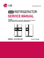
REFRIGERATOR
SERVICE MANUAL
CAUTION
PLEASE READ CAREFULLY THE SAFETY PRECAUTIONS OF THIS BOOK
BEFORE CHECKING OR OPERATING THE REFRIGERATOR.
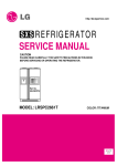
MODEL: GC-P227/L227
COLOR: TITANIUM
CONTENTS
WARNINGS AND PRECAUTIONS FOR SAFETY ................................................................................................................ 3
SPECIFICATIONS................................................................................................................................................................... 4
PARTS IDENTIFICATION ....................................................................................................................................................... 6
HOW TO INSTALL THE REFRIGERATOR .......................................................................................................................... 10
HOW TO ADJUST DOOR HEIGHT OF THE REFRIGERATOR ........................................................................................ 10
HOW TO INSTALL WATER PIPE ........................................................................................................................................11
HOW TO CONTROL THE AMOUNT OF WATER SUPPLIED TO THE ICEMAKER ......................................................... 15
MICOM FUNCTION .............................................................................................................................................................. 16
EXPLATION FOR MICOM CIRCUIT..................................................................................................................................... 26
EXPLANATION FOR PWB CIRCUIT ..................................................................................................................................26
ICE MAKER AND DISPENSER OPERATION PRINCIPLE AND REPAIR METHOD.......................................................... 41
OPERATION PRINCIPLE....................................................................................................................................................41
ICEMAKER FUNCTIONS....................................................................................................................................................42
DEFECT DIAGNOSIS FUNCTION......................................................................................................................................43
CIRCUIT ................................................................................................................................................................................ 44
TROUBLE DIAGNOSIS ........................................................................................................................................................ 45
TROUBLE SHOOTING ...................................................................................................................................................... 45
FAULTS .............................................................................................................................................................................. 55
COOLING CYCLE HEAVY REPAIR ................................................................................................................................... 72
HOW TO DEAL WITH CLAIMS .......................................................................................................................................... 79
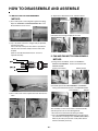
HOW TO DISASSEMBLE AND ASSEMBLE ....................................................................................................................... 84
DOOR................................................................................................................................................................................. 84
HANDLE ............................................................................................................................................................................. 85
SHROUD, GRILLE FAN ..................................................................................................................................................... 85
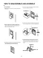
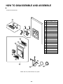
WATER VALVE DISASSEMBLY METHOD ........................................................................................................................ 86
FAN AND FAN MOTOR DISASSEMBLY METHOD ........................................................................................................... 86
DISPENSER....................................................................................................................................................................... 87
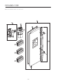
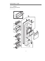
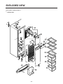
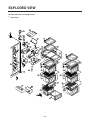
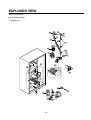
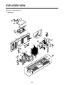
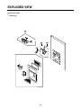
EXPLODED VIEW ................................................................................................................................................................ 89
-2-
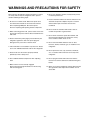
WARNINGS AND PRECAUTIONS FOR SAFETY
8. Do not fray, damage, machine, heavily bend, pull out,
or twist the power cord.
Please observe the following safety precautions in order to
use safely and correctly the refrigerator and to prevent
accident and danger during repair.
9. Please check the evidence of moisture intrusion in the
electrical components. Replace the parts or mask it
with insulation tapes if moisture intrusion was
confirmed.
1. Be care of an electric shock. Disconnect power cord
from wall outlet and wait for more than three minutes
before replacing PWB parts. Shut off the power
whenever replacing and repairing electric components.
10. Do not touch the icemaker with hands or tools to
confirm the operation of geared motor.
2. When connecting power cord, please wait for more than
five minutes after power cord was disconnected from the
wall outlet.
11. Do not let the customers repair, disassemble, and
reconstruct the refrigerator for themselves. It may
cause accident, electric shock, or fire.
3. Please check if the power plug is pressed down by the
refrigerator against the wall. If the power plug was
damaged, it may cause fire or electric shock.
12. Do not store flammable materials such as ether,
benzene, alcohol, chemicals, gas, or medicine in the
refrigerator.
4. If the wall outlet is over loaded, it may cause fire. Please
use its own individual electrical outlet for the refrigerator.
13. Do not put flower vase, cup, cosmetics, chemicals,
etc., or container with full of water on the top of the
refrigerator.
5. Please make sure the outlet is properly earthed,
particularly in wet or damp area.
14. Do not put glass bottles with full of water into the
freezer. The contents shall freeze and break the glass
bottles.
6. Use standard electrical components when replacing
them.
7. Make sure the hook is correctly engaged.
Remove dust and foreign materials from the housing
and connecting parts.
15. When you scrap the refrigerator, please disconnect the
door gasket first and scrap it where children are not
accessible.
-3-
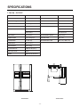
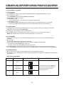
SPECIFICATIONS
1. Ref No. : GC-P227
ITEMS
SPECIFICATIONS
ITEMS
SPECIFICATIONS
DIMENSIONS (mm)
894(W)X790(D)X1753(H)
FIRST DEFROST
4 - 5 Hours
NET WEIGHT (kg)
132
DEFROST CYCLE
13 - 15 Hours
COOLING SYSTEM
Fan Cooling
DEFROSTING DEVICE
Heater, Sheath
TEMPERATURE CONTROL
Micom Control
ANTI SWEAT HEATER
Dispenser Duct Door Heater
DEFROSTING SYSTEM
Full Automatic
Dispenser Heater
Heater Defrost
Home Bar Heater
INSULATION
Cyclo-Pentane
ANTI-FREEZING HEATER
Damper Heater
COMPRESSOR
P.T.C. Starting Type
FREEZER LAMP
40W (1 EA)
EVAPORATOR
Fin Tube Type
REFRIGERATOR LAMP
40W (1 EA) / 30W (1 EA)
CONDENSER
Wire Condenser
REFRIGERANT
R134a (180g)
LUBRICATING OIL
FREOL @10G (310 cc)
CAPILLARY TUBE
ID 0.83
DRIER
MOLECULAR SIEVE XH-7
948
1753
790
1135.5
602
662
711
894
<Front View>
<Plane View>
-4-
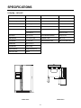
SPECIFICATIONS
2. Ref No. : GC-L227
ITEMS
SPECIFICATIONS
ITEMS
SPECIFICATIONS
DIMENSIONS (mm)
894(W)X790(D)X1753(H)
DRIER
MOLECULAR SIEVE XH-7
NET WEIGHT (kg)
129
FIRST DEFROST
4 - 5 Hours
COOLING SYSTEM
Fan Cooling
DEFROST CYCLE
13 - 15 Hours
TEMPERATURE CONTROL
Micom Control
DEFROSTING DEVICE
Heater, Sheath
DEFROSTING SYSTEM
Full Automatic
ANTI SWEAT HEATER
Dispenser Duct Door Heater
Heater Defrost
Dispenser Heater
INSULATION
Cyclo-Pentane
ANTI-FREEZING HEATER
Damper Heater
COMPRESSOR
P.T.C. Starting Type
FREEZER LAMP
40W (1 EA)
EVAPORATOR
Fin Tube Type
REFRIGERATOR LAMP
40W (1 EA) / 30W (1 EA)
CONDENSER
Wire Condenser
REFRIGERANT
R134a (180g)
LUBRICATING OIL
FREOL @10G (310 cc)
CAPILLARY TUBE
ID 0.83
948
1753
790
1135.5
602
662
711
894
<Front View>
<Plane View>
-5-
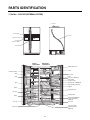
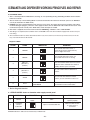
PARTS IDENTIFICATION
1. Ref No. : GC-P227 (INTERNAL FILTER)
Cover PWB
Frame Display
Water Tube
Dispenser Lamp
Ice & Water
Dispenser Button
Home Bar
Freezer
compartment
Refrigerator
compartment
Milk product corner
Lamp
Automatic Icemaker
Shelf
Door Rack
Lamp
Shelf
Can Server (Optional)
Wine holder
(Plastic or wire)
Refreshment center(Optional)
Shelf
Shelf (Folding or Normal)
Egg Box
Drawer
Vegetable Drawer
Door rack
Humidity Switch
Drawer
Miracle Zone (Optional)
Fresh compartment
(Optional)
Door rack
Door Rack
Conversion switch
(Meats/Vegetables)
(Optional)
Lower cover
-6-
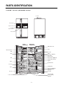
PARTS IDENTIFICATION
2. Ref No. : GC-P227 (EXTERNAL FILTER)
Cover PWB
Frame Display
Dispenser Lamp
Ice & Water
Dispenser Button
Home Bar
Freezer
compartment
Refrigerator
compartment
Milk product corner
Lamp
Automatic Icemaker
Shelf
Door Rack
Lamp
Shelf
Can Server (Optional)
Wine holder
(Plastic or wire)
Refreshment center(Optional)
Shelf
Shelf (Folding or Normal)
Egg Box
Drawer
Vegetable Drawer
Door rack
Humidity Switch
Drawer
Miracle Zone (Optional)
Fresh compartment
(Optional)
Door rack
Door Rack
Conversion switch
(Meats/Vegetables)
(Optional)
Lower cover
-7-
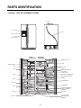
PARTS IDENTIFICATION
3. Ref No. : GC-L227 (INTERNAL FILTER)
Cover PWB
Frame Display
Water Tube
Dispenser Lamp
Ice & Water
Dispenser Button
Freezer
compartment
Refrigerator
compartment
Milk product corner
Lamp
Automatic Icemaker
Shelf
Door Rack
Lamp
Shelf
Can Server (Optional)
Wine holder
(Plastic or wire)
Refreshment center(Optional)
Shelf
Shelf (Folding or Normal)
Egg Box
Drawer
Vegetable Drawer
Door rack
Humidity Switch
Drawer
Miracle Zone (Optional)
Fresh compartment
(Optional)
Door rack
Door Rack
Conversion switch
(Meats/Vegetables)
(Optional)
Lower cover
-8-
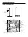
PARTS IDENTIFICATION
4. Ref No. : GC-L227 (EXTERNAL FILTER)
Cover PWB
Frame Display
Dispenser Lamp
Ice & Water
Dispenser Button
Freezer
compartment
Refrigerator
compartment
Milk product corner
Lamp
Automatic Icemaker
Shelf
Door Rack
Lamp
Shelf
Can Server (Optional)
Wine holder
(Plastic or wire)
Refreshment center(Optional)
Shelf
Shelf (Folding or Normal)
Egg Box
Drawer
Vegetable Drawer
Door rack
Humidity Switch
Drawer
Miracle Zone (Optional)
Fresh compartment
(Optional)
Door rack
Door Rack
Conversion switch
(Meats/Vegetables)
(Optional)
Lower cover
-9-
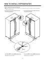
HOW TO INSTALL REFRIGERATOR
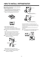
1. How to Adjust Door Height of Refrigerator
■ Make the refrigerator level first. (If the refrigerator is not installed on the flat floor, the height of freezer and refrigerator
door may not be the same.)
1. If the height of freezer door is lower than that of
refrigerator compartment :
Height
Difference
2. If the height of freezer door is higher than that of
refrigerator compartment :
Height
Difference
Height
Difference
Height
Difference
1 Adjusting
Screw
2 Driver
Insert a driver into the groove of adjusting screw
and rotate driver in arrow direction (clockwise) until the
refrigerator becomes horizontal.
Insert a driver into the groove of adjusting screw
and rotate driver in arrow direction (clockwise) until the
refrigerator becomes horizontal.
- 10 -
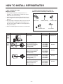
HOW TO INSTALL REFRIGERATOR
2. How to Install Water Pipe
2-1. When connecting directly to the water tap.
■ Before Installation
1. The icemaker requires the water pressure of 1.5 8.5kgf/cm2. (It is acceptable if city water fills a cup of
180cc with water for 3 seconds)
2. Install booster pump where the city water pressure is
below 1.5kgf/cm2 for normal operation of water and ice
dispenser.
3. The total length of water pipe shall be less than 12m. Do
not bend the pipe at right angle. If the length is more
than 12m, there will be troubles on water supply due to
water pressure drop.
4. Please install water pipe where there is no heat around.
■ Please confirm the following installation parts.
Valve Feed
Rubber, Packing
Connector, Pipe
Class.
Shape and Spec.
Nomenclature
Remarks
5221JA3001A
Common Use
No Holes
Valve Feed
Water
Connector
Connector, (MECH) Pipe
Conversion Connector(3/4")
Balance Conector(3/4")
Packing(ø24x3t)
4932JA3003A
6631JA3004A
6631JA3004B
3920JA3001B
4932JA3003B
Conversion Connector(W25)
Balance Conectoor(W25)
Packing(ø23x3t)
6631JA3004C
6631JA3004D
3920JA3001A
Connector, (MECH) Pipe
Conversion Connector(W28)
Balance Conector(W28)
Packing(ø26x3t)
4932JA3003C
6631JA3004E
6631JA3004F
3920JA3001C
Connector, (MECH) Pipe
Conversion Connector(1/2")
Balance Conector(1/2")
Packing(ø19x3t)
4932JA3003D
6631JA3004G
6631JA3004H
3920JA3001D
- 11 -
Tape, Teflon
P/No
Convertible
Water
Valve
Connector, (MECH) Pipe
Connector, Pipe
No Holes
No Holes
No Holes
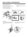
HOW TO INSTALL REFRIGERATOR
Caution : • Feed pipe should be connected to cold water
line. If it is connected to hot water line, trouble
may occur.
• Please check rubber packing when connecting
feed pipe.
1. Connection of Pipe Connector A and B.
1) Turn off main valve of water pipe.
2) Disconnect water tap from piping by loosening nuts.
3) Connect pipe connector A and B to piping after sealing
the pipe connector with sealing tapes.
4) Connect feed valve to pipe connector A.
5) If there is only one tap water pipe, connect pipe
connector A only and install feed pipe.
Single Lever Type Faucet
(general)
Pipe Connector B
Hot Water
General Type
Feed
Valve
Pipe Connector A
Feed
Valve
Feed
Valve
Cold Water
Two Hands Type Faucet
How to wind
Sealing Tapes.
Feed
Valve
Single Lever Type Faucet (one
hole, tech type and hand spray)
Feed
Valve
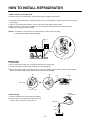
2. Water Supply
2) Check leakage at connecting part, then arrange water
tube and locate the refrigerator at its regular place if
there is no leaking.
1) After the installation of feed water, plug the refrigerator
to the earthered wall outlet, press the water dispenser
button for 2 - 3 minutes, and confirm that the water
comes out.
Water Tube
Water Tube
Nut
- 12 -
HOW TO INSTALL REFRIGERATOR
3. When customer uses bottled water.
*If customer wants to use bottled water, extra pump should be installed as shown below.
1. The pump system should not be on the floor (it may cause noise and vibration). Securely fasten the inlet and outlet
nuts of pump.
2. If there is any leakage after installation, cut the water tube at right angle and reassemble.
3. When put the water tube end into the bottle, leave a clearance between bottle bottom and water tube end.
4 Check water coming out and any leakage.
Caution : • If feed tube is more than 4m, less water will come out due to pressure drops.
• Use standard feed tube to prevent leaking.
■ Outternal Filter
1. Filter Fixation
1) There are two types of filter. One is nut type and the other is connector type.
2) Connect feed tube to the filter outlet and water valve connecting tube.
3) Fix the filter at proper place around the sink where it is easy to replace the filter and to receive the cleaning water.
Please consider the length of tube shall be less than 8m when locating filter.
Nut
Nut
Inlet
Outlet
or
Water Tube
Connector Type
Nut Type
Hot Water
Cold Water
2. Filter Cleaning
1) Connect feed tube to the inlet of feed valve and filter.
2) Clean the main valve and feed valve with water for at
least one minute until clean water comes out.
Filter Inlet
Filter
Water
- 13 -
Feed Valve
HOW TO INSTALL REFRIGERATOR
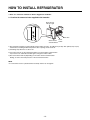
■ Install Water Filter (Applicable to some models only)
■ Before Installing water filter
1. Before installing the filter, take out the top shelf of the
refrigerator after tilting it to the direction () and lifting it
to the direction () and move it to the lower part.
2. Remove the lamp cover by pressing the protrusion
under the cover and pulling the cover to the front.
Control box
Aligning with the guide line
and the fastening indication line
Control box
Aligning with the guide line
and the loosening indication line
■ Installing water filter
1. Initial installation of water filter
Remove the filter substitute cap by turning it
counterclockwise () by 90 degrees and pulling it down.
■ After installing water filter
Reassemble the lamp cover and the top shelf of the
refrigerator. To place the top shelf of the refrigerator, raise
the front part of the shelf a bit so that the hook of the shelf
is fit into the groove.
In order to clean the water filter system, drain water for
about 3 min.
Note : Keep it safe to use it later when you do not use the
filter.
Note : Then open the door of the refrigerator and check for
water droppings on the shelf under the filter.
Remove the red cap from the filter and attach the
sticker. Insert the upper part of the filter () after
aligning with the guideline marked on the control box,
and fasten it by turning it clockwise by 90 degrees.
Note : Check that the guideline and the fastening
indication line are aligned.
Substitute
cap
Separation
of red cap
Adhesion
sticker
2. Replacement of water filter
While holding the lower part of the filter, turn it
counterclockwise () by 90 degrees and pull it down.
Note : Check that the guideline and the loosening
indication line are aligned.
- 14 -
HOW TO INSTALL REFRIGERATOR
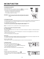
3. How to Control the Amount of Water Supplied to Icemaker.
3-1. Confirm the amount of water supplied to the icemaker.
Water Amount
Indicator Light
Feeler Arm
Water Amount
Selection Button
Power
Switch
1) The automatic icemaker can automatically make 6 cubes at a time, 70~120 pieces per day. This quantity may vary by
circumstance, including ambient temperature, door opening, freezer load. etc.
2) Icemaking stops when the ice bin is full.
3) If you don't want to use the automatic icemaker, turn the icemaker switch to OFF.
If you want to use automatic icemaker again, change the switch to ON.
4) The water amount will vary depending on the water amount selection button.
Setting, as well as the water pressure of the connected water line.
NOTE
• It is normal that a noise is produced when ice drops into the ice storage bin.
- 15 -
MICOM FUNCTION
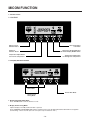
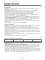
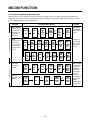
1. Monitor Panel
1-1. GC-P227
Expres Freezer
Selection Button
Door Alarm Button/
Lock Button
Dispenser
Selection Button
Dispenser Light On/Off Button/
Filter Status Display RESET Button
Temperature Adjust Button
For Freezer Compartment
Temperature Adjust Button
For Refrigerator Compartment
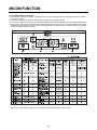
1-2. Display Second Function
Demo Mode
Buzzer Mute Mode
Display Power
Saving Mode
1. Door Alarm Buzzer Mute Mode
Press ALARM/LOCK to turn the buzzer on or off.
2. Display Power saving Mode
It places display in standby mode until door is opened.
Press FREEZER and EXPRESS FRZ. buttons simultaneously to turn all LEDs ON and then OFF with the recognition
sound of Ding~ after 5 seconds. (Be sure not to press only one button to work.)
- 16 -
MICOM FUNCTION
Once the mode activates, the display is always OFF. Until door is opened or display button is pressed. When 20 seconds
has elapsed after closing door or pressing button, the display turns OFF. To deactivate this mode is same as the activation
methods. The mode inactivates when resetting the power.
3. Exhibition Mode
Demo mode is available for displaying the refrigerator in a sales setting or similar condition.
It allows the display, dispenser, lights, and fan to operate without running the compressor.
To enter the DEMO mode, press and hold the REFRIGERATOR and EXPRESS FRZ. buttons simultaneously for 5
seconds until the Ding~ sounds.
To exit the DEMO mode and return to normal operation, press and hold the REFRIGERATOR and EXPRESS FRZ.
buttons simultaneously for 5 seconds until the Ding~ sounds again.
The refrigerator will default to the NORMAL mode (DEMO mode OFF) if the power fails.
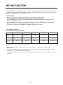
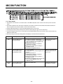
2. Description of Function
2-1-1. Funnction of Temperature Selection
Division
Temperature
Control
Freezer Control
Refrigeration
Control
Power Initially On
1st Press
2st Press
3th Press
4th Press
Medium
Medium Max
Max
Min
Medium Min
-19 °C
-22 °C
-23 °C
-15 °C
-17 °C
3 °C
2 °C
0°C
6 °C
4 °C
* The temperature can vary ±3 °C depending on the load condition.
❉ Whenever pressing button, setting is repeated in the order of (Medium) ➝ (Medium Max) ➝ (Max) ➝ (Min) ➝
(Medium Min).
• The actual inner temperature varies depending on the food status, as the indicated setting temperature is a target
temperature, not actual temperature within refrigerator.
• Refrigeration function is weak in the initial time. Please adjust temperature as above after using refrigerator for minimum
2~3 days.
- 17 -
MICOM FUNCTION
2-1-2. LCD Back Light Control
1. In order to easily view display status on the LCD, LCD Back Light is turned on for a minute in application of initial power,
for a minute in button manipulation and for a minute after closing time from opening time of door.
2. If pressing any display button once with the backlight turned off, buzzer rings and button function is not performed but
only backlight is turned on (If pressing the first button with the back light turned off, only back light ON function is
performed).
3. If pressing the special freezing button and the freezing temperature adjustment button for more than a second, the back
light is turned on and all the graphics of LCD are turned on. If releasing the button, the LCD graphic is displayed in the
previous status and the back light is turned off (check LCD graphic and back light ON/OFF status).
2-1-3. Outside temperature display function
1. Outside temperature sensor at the left U of refrigerator senses ambient temperature and displays the outside temperature
in the left side of “Outside temperature” text on the LCD of the display part.
2. Ambient temperature is displayed up to -9°C ~ 49°C and displayed as “Lo” for less than -10°C and as “HI” for more than
50°C. If the ambient temperature sensor fails, it is displayed as “Er”.
3. Since display temperature of outside temperature is temperature sensed by the ambient sensor in the hinge U of the
freezing room, it may differ from the outside temperature display of other household electrical appliances.
2-1-4. Lock function (display button lock)
1. In power application of refrigerator, the LOCK text is turned off at the right side of lock graphic of display with the lock
replease status.
2. If desiring to lock the dislay the dispenser and control panel, push on the LOCK button more than 3 seconds. LOCK is
turned on at the right side of lock graphic of display with lock status.
3. The buzzer sound and control panel and dispenser function is not performed even if pressing display button other than
lock key in the lock status.
4. If desiring to release the lock status and pressing the lock button more than 3 seconds. LOCK text is turned off at the right
side of lock graphic of display with the lock release status.
2-1-5. Filter condition display function
1. There is a replacement indicator light for the water filter cartridge on the dispenser.
2. Water filter needs replacement once six months.
3. Water filter light and FILTER RESET HOLD 3SECS text turn on to tell you need to replace the filter soon.
4. After replacing the filter, press and hold the lock button more than 3seconds.
Then water filter light and FILTER RESET HOLD 3SECS text turn off with reset status.
- 18 -
MICOM FUNCTION
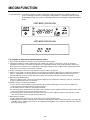
2-2. Dispenser use selection
You can select water or ice.
DISPENSER
❉ Please select water, slice ice and square ice by pressing
button as you desire.
❉ Please press the push button lightly by catching and pushing in cup.
• The border line is indicated for the selected function.
• “Tak!” sounds if 5 seconds pass after ice comes out.
It is sound that the outlet of ice is closed.
REFERENCE : Please wait for 2-3 seconds in order to take final ice slices or drops of
water when taking out cup from the pressing switches after taking ice
or water.
Pressing
Switch
2-3. Automatic ice maker
• The automatic ice maker can automatically make 8 pieces of ice cube at a time, 80 pieces a day. But these quantities may
be varied according to various conditions including how many times the refrigerator door opens and closes.
• Ice making stops when the ice bin is full.
• If you don’t want to use automatic ice-maker, change the ice-maker switch to ON-OFF.
If you want to use automatic ice-maker again, change the switch to OFF-ON.
NOTE : It is normal that a noise is produced when ice made is dropped into the ice bin.
2-4. When ice maker does not operate smoothly
Ice is lumped together
• When ice is lumped together, take the ice lumps out of the ice bin, break them into small pieces, and then place them into
the ice bin again.
• When the ice maker produces too small or lumped together ice, the amount of water supplied to the ice maker need to
adjusted. Contact the service center.
✻ If ice is not used frequently, it may lump together.
Power failure
• Ice may drop into the freezer compartment. Take the ice bin out and discard all the ice then dry it and place it back. After
the machine is powered again, crushed ice will be automatically selected.
The unit is newly installed
• It takes about 12 hours for a newly installed refrigerator to make ice in the freezer compartment.
2-5. Express Freezer
Please select this function for prompt freezer.
• “On” or “Off” is repeated whenever pressing
button.
• The arrow mark graphic remains at the On status after flickering 4 times
when selecting Special Refrigeration “On”.
• Super freezer function automatically turns off if a fixed time passes.
2-6. Lock
This button stops operation of different button.
• Locking or Release is repeated whenever pressing the
.
• Pressing the other button when selecting ‘ALARM/LOCK’, the button does
not operate.
- 19 -
MICOM FUNCTION
2-7. Super freezing
1. EXPRESS FRZ freezing is a function to increase the cooling speed of the freezer compartment by running both the
compressor and the fan simultaneously.
2.EXPRESS FRZ is cancelled and the refrigerator returns to its default setting in the event of a power interruption.
3. SelectingEXPRESS FRZ changes only the speed of the cooling without affecting the set temperature.
4. The temperature can be adjusted even when EXPRESS FRZ has been selected and is in progress.
5. The freezer operates at whatever temperature was set at the time EXPRESS FRZ was selected.
6. If you select EXPRESS FRZ, the compressor and fan will run until it is deselected or the cycle time has elapsed.
(3 hours : compressor and fan run / 3 ~ 24 hours : COLDEST operation)
7. If a defrost cycle occurs while an EXPRESS FRZ is already running, EXPRESS FRZ runs for its remaining cycle time
after the defrost cycle is completed. If the defrost cycle takes longer than 30 minutes, EXPRESS FRZ will run for only 2
hours at the end of the defrost cycle.
8. If you press EXPRESS FRZ during a defrost cycle, the EXPRESS FRZ indicator (LCD or LED, depending upon the
model) will illuminate but the compressor will not operate until the defrost cycle is complete.
9. If you press EXPRESS FRZ within 7 minutes of compressor cut-off, the compressor will not operate until the 7-minute
delay has passed.
10. The freezer fan motor runs at high speed during the EXPRESS FRZ cycle.
2-8. *Miracle Zone function
1. Miracle Zone is located at the bottom room of R-room and maintains optimum temperature depending on foods through
selection of desired foods kept in the Miracle Zone from vegetables to meat with a display.
Set temperature in the Miracle Zone by using a separate selection button at the right side of the Miracle Zone. Initial
notch is in “veg.”status in application of power. Whenever pressing buttons, notch changes while LED is displayed in the
order of “veg. → cheeze → meat → veg.”.
Provided that selected notch LED turns off if opening doors of the R-room and it turns off if closing doors of R-room.
2. Temperature of the miracle zone is controlled with a stemping damper at the left side of the miracle zone and controlled
with a miracle zone at the rear side of miracle zone.
3. Change of the notch by temperature control S/W at the miracle zone is controlled after 10 seconds have passed after
selecting final notches.
4. Miracle zone damper is forcedly closed during test mode or defrost mode.
2-9. Control of variable type of freezing room fan
Miracle Zone NOTCH
meat
cheeze
veg.
Setting Indication
-1°C
2°C
4°C
1. To increase cooling speed and load response speed, MICOM variably controls freezing room fan motor at the high speed
of RPM and standard RPM.
2. MICOM only operates in the input of initial power or super freezing operation or load response operation for the high
speed of RPM and operates in the standard RPM in other general operation.
3. If opening doors of freezing / cold storage room or home bar while fan motor in the freezing room operates, the freezing
room fan motor normally operates (If being operated in the high speed of RPM, it converts operation to the standard
RPM). However, if opening doors of freezing room or home bar, the freezing room fan motor stops.
4. As for monitoring of BLDC fan motor error in the freezing room, MICOM immediately stops the fan motor by determining
that the BLDC fan motor is locked or poor if there would be position signal for more than 115 seconds at the BLDC motor.
Then it displays failure (refer to failure diagnosis function table) at the display part of refrigerator, the BLDC motor doesn’t
operate more. If you want to operate the BLDC motor, turn off and on power resource.
- 20 -
MICOM FUNCTION
2-10. Control of M/C room fan motor
1. The M/C room fan motor performs ON/OFF control by linking with the COMP.
2. It controls at the single RPM without varying RPM.
3. Failure sensing method is same as in fan motor of freezing fan motor (refer to failure diagnosis function table for failure
display).
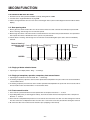
2-11. Door opening alarm
1. Buzzer generates alarm sound if doors are not closed even when more than a minute consecutively has passed with
doors of freezing / cold storage room or home bar opened.
2. Buzzer rings three times in the interval of 0.5 second after the first one-minute has passed after doors are opened and
then repeats three times of On/Off alarm in the cycle of every 30 seconds.
3. If all the doors of freezing / cold storage room or home bar are closed during door open alarm, alarm is immediately
released.
Doors of freezing /
cold storage room Closing Opening Closing
or home bar
Opening
Closing
3 Times 3 Times 3 Times 3 Times
BUZZER
Within
a minute
A minute
30
30
30
seconds seconds seconds
2-12. Ringing of button selection buzzer
1. If pressing the front display button, “Ding ~ “ sound rings.
2-13. Ringing of compulsory operation, compulsory frost removal buzzer
1. If pressing the test button in the main PCB, “Phi ~ “ sound rings.
2. In selecting compulsory operation, alarm sound is repeated and completed in the cycle of On for 0.2 second and Off for
1.8 second three times.
3. In selecting compulsory frost removal, alarm sound is repeated and completed in the cycle of On for 0.2 second , Off for
0.2 second, On for 0.2 second and Off for 1.4 second three times.
2-14. Frost removal function
1. Frost removal is performed whenever total operation time of compressor becomes 7 ~ 7.5 hour.
2. In providing initial power (or returning power failure), frost removal starts whenever total operation time of compressor
becomes 4 ~ 4.5 hour.
3. Frost removal is completed if temperature of a frost removal sensor becomes more than 5°C after starting frost removal.
Poor frost removal is not displaced if it does not arrive at 5°C even if two hours have passed after starting frost removal.
4. No removal is done if frost removal sensor becomes poor (snapping or short-circuit).
- 21 -
MICOM FUNCTION
2-15. Sequential operation of built-in product
Built-in products such as compressor, frost removal heater, freezing room fan, Cooling Fan and step motor damper are
sequentially operated as follows for preventing noise and part damage occurred due to simultaneous operation of a lot of
parts in applying initial power and completing test.
Function
When temperature
of a frost removal
sensor becomes
more than 45°C
(In purchase,
movement)
In applying Initial power
When
temperature of a
frost removal
sensor becomes
less than 45°C
(In power failure,
service)
Load Operation Sequence
POWER
ON
0.3
sec.
F-FAN
&
C-FAN
ON
0.3
sec.
R-STEP
MOTOR
DAMPER
ON
MIRACLE
ZONE
0.3
STEP
sec.
DAMPER
MOTOR
ON
0.3
sec.
HOME
BAR
HEATER
ON
If error occurs
during operation,
initial operation is
not done.
■ Sequence of
ON
DISP'
HEATER
ON
TEST MODE
Test mode 2
(Compulsory frost
removal)
COMP
ON
0.3
POWER sec.
0.3 PIPE
&
sec.
Test mode 1
(Compulsory
function)
0.3
sec.
Remark
TEST
S/W
(PRESS
Once)
TEST
S/W
(PRESS
2 Times)
6
sec.
FROST
REMOVAL
HEATER
ON
5
sec.
FROST
REMOVAL
HEATER
OFF
0.3
sec.
HOME
BAR
HEATER
ON
5
sec. HOME
BAR
HEATER
OFF
0.3
sec.
DAMPER 5 DAMPER
sec.
&
&
DUCT DOOR
DUCT DOOR
HEATER
HEATER
ON
OFF
load operation
when closing
F-room and
R-room.
MIRACLE
PIPE 0.3
0.3
0.3
0.3 ZONE 0.3
F-FAN
R-STEP
&
sec. COMP sec.
sec.
sec.
sec. HOME
STEP
&
BAR
MOTOR
DISP'
DAMPER
C-FAN
HEATER
DAMPER
HEATER
ON
MOTOR
ON
ON
ON
OFF
ON
OTHER
LOAD
0.3
sec.
COMP
0.3
sec.
ON
OFF
COMP
OFF
0.3
sec.
F-FAN
&
C-FAN
OFF
- 22 -
F-FAN
&
C-FAN
ON
0.3
sec.
R-STEP
0.3
sec. MOTOR
DAMPER
ON
FROST
REMOVAL
HEATER
ON
0.3
sec.
0.3
sec.
MIRACLE
ZONE
STEP
DAMPER
MOTOR
CLOSE
R-STEP
MOTOR
DAMPER
CLOSE
If pressing switch
once more in the
test mode 2 or
temperature of a
frost removal
sensor is more
than 5°C, it
immediately
returns to the test
mode for initial
operation
(COMP operates
after 7 minutes).
MICOM FUNCTION
2-16. Failure Diagnosis Function
1. Failure diagnosis function is function to facilitate service when nonconforming matters affecting performance of product
during use of product.
2. In occurrence of failure, pressing the function adjustment button does not perform function.
3. If nonconforming matters occurred are released during display of failure code, MICOM returns to the original state (Reset).
4. Failure code is displayed on the display part of setting temperature for the freezing room and the display part of setting
temperature for the cold storage room of LCD, which are placed at the display part of a refrigerator. All the LCD graphics
other than a failure code are turned off.
✽ All LCDs turn off other than freezer room notch temperature display and refrigerator room notch temperature
display(failure code indication part) in case of indicating failure modes(except for Note1, Note2).
- 23 -
MICOM FUNCTION
2-17. Test Function
1. The purpose of test function is to check function of the PWB and product and to search for the failure part at the failure
status.
2. Test button is placed on the main PCB of refrigerator (test switch), and the test mode will be finished after maximum 2
hours irrespective of test mode and then is reset to the normal status.
3. Function adjustment button is not perceived during performance of test mode.
4. In finishing test mode, always pull the power cord out and then plug-in it again for the normal state.
5. If nonconforming contents such as sensor failure are found during performance of test mode, release the test mode and
display the failure code.
6. Even if pressing the test button during failure code display, test mode will not be performed.
Mode
Operation
Contents
Remarks
Test 1
Press test button once
(strong cold mode)
1. Continuous operation of compressor
2. Continuous operation of freezing bldc motor
(high-speed RPM) and cooling bldc motor
3. Defrost heater turns off
4. Stepping motor damper is completely
opened (open of baffle)
5. Miracle zone stepping motor damper is
completely closed.
6. All display LCD graphics turns on.
Freezing fan turns off in
door opening
Test 2
Press test button once at
the test mode 1 status
(forced defrost mode)
1. Compressor OFF
2. Freezing bldc motor and cooling bldc motor
turn off
3. Defrost heater turns on
4. Stepping motor damper is completely
closed (closing of baffle)
5. Miracle zone stepping motor damper is
completely closed.
6. All display LCD graphics turns off (only LCD
turns on for(A) “MIDIUM” status, (B)
“MIDIUM” status)
Return to the normal mode
when the defrost sensor is
above +5°C
Normal
Status
Press test button once at
the test mode 2 status
Return to the initial status.
Compressor will operate
after delay for 7 minutes
- 24 -
MICOM FUNCTION
✻ LCD check function: If simultaneously pressing super freezer button and freezing temperature adjustment button for a
second, a back light is turned on and all display LCD graphics on. If releasing the button, the LCD
graphic displays the previous status, the back light is turned off (LCD graphic and back light ON/OFF
check).
<TEST MODE 1 STATUS LCD>
<TEST MODE 2 STATUS LCD>
2-18. Function of dispenser and water dispenser built-in
1. This is function allowing ice and water to come outside without opening door.
2. If pressing the dispenser switch (rubber button) after selecting ice (cube ice, crushed ice) or water, ice and water
equivalent to each come out. However, the duct doors are opened by electrical solenoid valve (Duct Door Solenoid) if
pressing the press switch in case of selecting ICE. If pressing the dispenser press switch and then detaching the hands,
the duct door is closed after it is opened for 5 seconds.
3. Function allowing ice and water to come stops if freezing room doors are opened.
4. If there is no Off signal even when 3 minutes have passed while pressing the dispenser press switch after selecting ice
(cube ice, crushed ice) or water, geared motor and solenoid (Cube, Water) is automatically turned off. However, the
solenoid (duct door) is stop 5 seconds after Off (to prevent short-circuit of a coil due to overheat of solenoid).
5. Dispenser Lamp On/Off function
Lamp on the dispenser part is turned on if pressing the dispenser press switch after selecting ice (cube ice, crushed ice)
or water. If detaching the hands, it is turned off.
6. Selection function of water/crushed/ cube ice
1) This is function to allow selection of water/crushed/ cube ice function depending on user’s selection. Display and
selection is done if pressing the dispenser selection button.
2) In the initial Power On, cube ice is automatically selected.
3) In selecting cube ice, geared motor is operated so that crushed ice can be supplied outside if pressing the press switch
when ice is formed in the ice storage container (Bank, Ice).
4) In selecting cube ice, geared motor is operated so that cube ice can be supplied outside if pressing the press switch
when ice is formed in the ice storage container (Bank, Ice).
7. Water dispenser function
1) LCD is displayed for selection if user selects water at the function adjustment part.
2) Water dispenser function is a type directly connected to a water pipe. The water solenoid valve built-in at the right side
of the M/C room is opened so that water can be supplied if selecting Water from the function adjustment part and then
pressing the press switch.
- 25 -
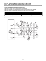
EXPLATION FOR MICOM CIRCUIT
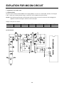
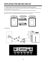
1. Explanation for PWB circuit
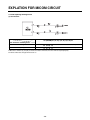
1-1. Power circuit
The power circuit includes a Switched Mode Power Supply (SMPS). It consists of a rectifier (BD1 and CE1) converting AC
to DC, a switch (IC2) switching the DC voltage, a transformer, and a feedback circuit (IC3 and IC4).
Caution : Since high voltage (310 Vdc) is maintained at the power terminal, wait at least 3 minutes after unplugging the
appliance to check the voltages to allow the current to dissipate.
Voltage of every part is as follows:
Part
Voltage
VA1
230 Vac
CE1
310 Vdc
CE2
16 Vdc
(1) GC-P227/L227
- 26 -
CE3
12 Vdc
CE4
16 Vdc
CE5
5 Vdc
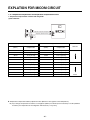
EXPLATION FOR MICOM CIRCUIT
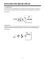
1-2. Oscillation circuit
The oscillation circuit generates a basic clock signal for synchronization and time calculation related to the transmission of
data and calculations made by the MICOM (IC1). The oscillator (OSC1) must always be replaced with an exact replacement
part. If this specification is changed, the change will affect the time calculations of the MICOM and it might not work at all.
(1) GC-P227/L227
1-3. Reset circuit
The RESET circuit allows various parts of the MICOM, such as RAM, defrosting, etc., to be restarted from the initial state
when power is interrupted or restored. A LOW signal applied to the reset terminal for 10 ms causes the MICOM to reset
itself. During normal operation, the voltage at the reset terminal is 5 Vdc. If the reset fails, the MICOM will not operate.
(1) GC-P227/L227
- 27 -
EXPLATION FOR MICOM CIRCUIT
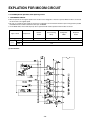
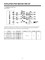
1-4. Load/dispenser operation, door opening circuit
1. LOAD DRIVING CIRCUIT
✽ The fan operates at the regular speed even if the door of the refrigerator or freezer is opened. When the doors are closed,
the fan reverts to its original speed.
✽ (A), (B), (C), and (D) of door switch for the freezer or refrigerator are connected to the door open sensing circuit in parallel
toward both ends of switch to determine door open at MICOM.
✽ In the TEST mode, the fan will stop if any door is opened. It will resume operation when the door is closed.
Type of Load
Measuring part (IC6)
Status
Compressor
IC6-16
Defrost
Heater
AC Converting
Relay
IC6-13
IC6-12
ON
Within 1 V
OFF
12 V
(1) GC-P227/L227
- 28 -
Refrigerator
LAMP
IC6-15
Dispenser
Heater
IC6-14
EXPLATION FOR MICOM CIRCUIT
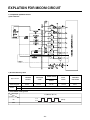
1-5. Dispenser operation circuit
(1) GC-P227/L227
1) Check load driving status
Type of Load
Measuring part
Status
GEARED
MOTOR
IC7-15
WATER VALVE
SOLENOID
CUBE
WATER
IC7-14
IC7-13
ON
Within 1 V
OFF
12 V
PILOT
VALVE
IC7-12
2) Lever Switch sensing circuit
Measuring part
IC1(Micom) (No. 16)
Lever S/W
On
5V
(60 Hz)
0V
OFF
5V
- 29 -
SOLENOID
DISPENSER
IC7-11
EXPLATION FOR MICOM CIRCUIT
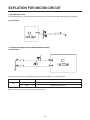
1-6. Door opening sensing circuit
(1) GC-P227/L227
Measuring part
IC1 (MICOM) No. (44, 45) / (45, 46) / (47, 48) Pin
Door of Freezer and Refrigerator
Closing
5 V ( A - B , C - D . Switch at both ends are at Off status)
Opening
0 V ( A - B , C - D . Switch at both ends are at On status)
✽ Since door switches (A) and (B) are interconnected, if either fails, the other will not respond properly.
✽ If either switch fails, the light will not come on.
- 30 -
EXPLATION FOR MICOM CIRCUIT
1-7. Temperature sensing circuit
(1) GC-P227/L227
The circuits involving the freezer and refrigerator sensors control the temperature in both the freezer and the refrigerator.
The icemaker sensor detects when ice is made. The defrost sensor determines both the need for defrosting and the
efficiency of the defrost operation. See the table below for voltages and checkpoints.
SENSOR
CHECK POINT
Freezing sensor
POINT A Voltage
Defrost sensor
POINT B Voltage
Refrigerator sensor 1
POINT C Voltage
Refrigerator sensor 2
POINT D Voltage
Magic room/ Opti Fresh Sensor
POINT E Voltage
- 31 -
NORMAL(-22 °F ~ 122 °F)
IN SHORT
IN OPEN
0.5 V~4.5 V
0V
5V
EXPLATION FOR MICOM CIRCUIT
1-8. Switch entry circuit
The following circuits are sensing signal form the damper motor reed switch for testing and diagnosing the refrigerator.
(1) GC-P227/L227
1-9. Option designation circuit (model separation function)
(1) GC-P227/L227
The circuits shown above vary according to which features are included on your particular model.
Separation
Connection Status
Application Standard
Connection
Miracle Zone exist
OUT
Miracle Zone don’t exist
OP1
uThese circuits are preset at the factory and cannot be altered.
- 32 -
EXPLATION FOR MICOM CIRCUIT
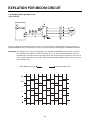
1-10. Stepping motor operation circuit
(1) GC-P227/L227
The motor is driven by magnetism formed in the areas of the coils and the stator. Rotation begins when a HIGH signal is
applied to MICOM Pin 33 of IC10 (TA7774F). This causes an output of HIGH and LOW signals on MICOM pins 34 and 35.
Explanation) The stepping motor is driven by sending signals of 3.33 mSEC via MICOM pins 33, 34, and 35, as shown in
the chart below. These signals are output via terminals 10, 11, 14, and 15 via input terminals 3, 6, and 8 of
IC10 (TA7774F), the motor drive chip. The output signals allow the coils wound on each phase of the stator to
form a magnetic field, which causes rotation. Input to the terminals INA and INB of IC10 as shown in the chart
below drives the motor.
CCW (Reverse rotation)
(Positive rotation) CW
INA
INB
A
B
A
B
- 33 -
EXPLATION FOR MICOM CIRCUIT
1-11. Fan motor driving circuit (freezer, mechanical area)
1. The circuit cuts all power to the fan drive IC, resulting in a standby mode.
2. This circuit changes the speed of the fan motor by varying the DC voltage between 7.5 Vdc and 16 Vdc.
3. This circuit stops the fan motor by cutting off power to the fan when it senses a lock-up condition.
a , d part
b part
e part
Motor OFF
5V
2V or less
2V or less
Motor ON
2 ~ 3V
12 ~ 14V
8 ~ 16V
(1) GC-P227/L227
b
a
e
d
- 34 -
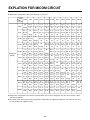
EXPLATION FOR MICOM CIRCUIT
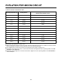
1-12. Temperature compensation and temperature compensation circuit
1. Temperature compensation in freezer and refrigerator
(1) GC-P227/L227
Temperature compensation at refrigerator
Temperature compensation at freezer
Freezer
Refrigerator
Resistance value
(RCF1)
Temperature
compensation
Resistance value
(RCR1)
Temperature
compensation
Remarks
180 kΩ
+5 °C [+9°F]
180 kΩ
+2.5 °C [+4.5°F]
Warmer
56 kΩ
+4 °C [+7.2°F]
56 kΩ
+2.0 °C [+3.6°F]
33 kΩ
+3 °C [+5.4°F]
33 kΩ
+1.5 °C [+2.7°F]
18 kΩ
+2 °C [+3.6°F]
18 kΩ
+1.0 °C [+1.8°F]
12 kΩ
+1 °C [+1.8°F]
12 kΩ
+0.5 °C [+0.9°F]
10 kΩ
0 °C [0°F]
10 kΩ
0 °C [0°F]
8.2 kΩ
-1 °C [-1.8°F]
8.2 kΩ
-0.5 °C [-0.9°F]
5.6 kΩ
-2 °C [-3.6°F]
5.6 kΩ
-1.0 °C [-1.8°F]
3.3 kΩ
-3 °C [-5.4°F]
3.3 kΩ
-1.5 °C [-2.7°F]
2 kΩ
-4 °C [-7.2°F]
2 kΩ
-2.0 °C [-3.6°F]
470 Ω
-5 °C [-9°F]
470 Ω
-2.5 °C [-4.5°F]
Reference temperature
Cooler
u Temperature compensation table by adjustment value (difference value against current temperature)
Ex) If you change compensation resistance at a refrigerator (RCR1) from 10 kΩ (current resistance) to 18 kΩ (modified
resistance), the temperature at the refrigerator will increase by +1°C[+1.8°F].
- 35 -
EXPLATION FOR MICOM CIRCUIT
u Temperature compensation table at the refrigerator is as follows:
Modification
resistance
470 Ω
Current
resistance
2 kΩ
3.3 kΩ
5.6 kΩ
8.2 kΩ
10 kΩ
12 kΩ
18 kΩ
33 kΩ
56 kΩ
No
470Ω
0.5 °C
1 °C
1.5 °C
2 °C 2.5 °C
3 °C
3.5 °C
4 °C
4.5 °C
[0.9 °F] [1.8 °F] [2.7 °F] [3.6 °F] [4.5 °F] [5.4 °F] [6.3 °F] [7.2 °F] [8.1 °F]
change
Up
Up
Up
Up
Up
Up
Up
Up
Up
2 kΩ
0.5 °C
No
0.5 °C
1 °C
1.5 °C 2 °C
2.5 °C
3 °C
3.5 °C
4 °C
4.5 °C
[0.9 °F]
[0.9 °F] [1.8 °F] [2.7 °F] [3.6 °F] [4.5 °F] [5.4 °F] [6.3 °F] [7.2 °F] [8.1 °F]
Down change
Up
Up
Up
Up
Up
Up
Up
Up
Up
1 °C
0.5 °C
No
3.3 kΩ [1.8 °F] [0.9 °F]
Down
Down
change
1.5 °C
1 °C
0.5 °C
5.6 kΩ [2.7 °F] [1.8 °F] [0.9 °F]
Down
Down
Down
Refrigerator
180 kΩ
0.5 °C
1 °C 1.5 °C
2 °C
2.5 °C
3 °C
3.5 °C
4 °C
[0.9 °F] [1.8 °F] [2.7 °F] [3.6 °F] [4.5 °F] [5.4 °F] [6.3 °F] [7.2 °F]
Up
Up
Up
Up
Up
Up
Up
Up
No
0.5 °C 1 °C
1.5 °C
2 °C
2.5 °C
3 °C
3.5 °C
[0.9 °F] [1.8 °F] [2.7 °F] [3.6 °F] [4.5 °F] [5.4 °F] [6.3 °F]
Up
Up
Up
Up
Up
Up
Up
change
2 °C
1.5 °C
1 °C
0.5 °
8.2 kΩ [3.6 °F] [2.7 °F] [1.8 °F] [0.9 °F]
Down
Down
Down
Drop
(RCR1)
5 °C
[9 °F]
Up
No
0.5 °C
1 °C
1.5 °C
2 °C
2.5 °C
3 °C
[0.9 °F] [1.8 °F] [2.7 °F] [3.6 °F] [4.5 °F] [5.4 °F]
change
Up
Up
Up
Up
Up
Up
10 kΩ
2.5 °C
2 °C
1.5 °C
1 °C
0.5 °C
No
0.5 °C
1 °C
1.5 °C
2 °C
2.5 °C
[4.5 °F] [3.6 °F] [2.7 °F] [1.8 °F] [0.9 °F]
[0.9 °F] [1.8 °F] [2.7 °F] [3.6 °F] [4.5 °F]
Down
Down
Down
Down
Down change
Up
Up
Up
Up
Up
12 kΩ
3 °C
2.5 °C
2 °C
1.5 °C
1 °C 0.5 °C
[5.4 °F] [4.5 °F] [3.6 °F] [2.7 °F] [1.8 °F] [0.9 °F]
Down
Down
Down
Down
Down
Down
18 kΩ
3.5 °C
3 °C
2.5 °C
2 °C
1.5 °C 1 °C
0.5 °C
No
0.5 °C
1 °C
1.5 °C
[6.3 °F] [5.4 °F] [4.5 °F] [3.6 °F] [2.7 °F] [1.8 °F] [0.9 °F]
[0.9 °F] [1.8 °F] [2.7 °F]
Down
Down
Down
Down
Down
Down
Down
change
Up
Up
Up
33 kΩ
4 °C
3.5 °C
3 °C
2.5 °C
2 °C 1.5 °C
1 °C
0.5 °C
[7.2 °F] [6.3 °F] [5.4 °F] [4.5 °F] [3.6 °F] [2.7 °F] [1.8 °F] [0.9 °F]
Down
Down
Down
Down
Down
Down
Down
Down
56 kΩ
4.5 °C
4 °C
3.5 °C
3 °C
2.5 °C 2 °C
1.5 °C
1 °C
0.5 °C
[8.1 °F] [7.2 °F] [6.3 °F] [5.4 °F] [4.5 °F] [3.6 °F] [2.7 °F] [1.8 °F] [0.9 °F]
Down
Down
Down
Down
Down
Down
Down
Down
Down
180 kΩ
5 °C
[9 °F]
Down
No
0.5 °C
1 °C
1.5 °C
2 °C
[0.9 °F] [1.8 °F] [2.7 °F] [3.6 °F]
change
Up
Up
Up
Up
No
0.5 °C
1 °C
[0.9 °F] [1.8 °F]
change
Up
Up
No
0.5 °C
[0.9 °F]
change
Up
4.5 °C
4 °C
3.5 °C
3 °C 2.5 °C
2 °C
1.5 °C
1 °C
0.5 °C
[8.1 °F] [7.2 °F] [6.3 °F] [5.4 °F] [4.5 °F] [3.6 °F] [2.7 °F] [1.8 °F] [0.9 °F]
Down
Down
Down
Down
Down
Down
Down
Down
Down
No
change
u Temperature compensation at the freezer is performed the same as at the refrigerator. The value for the freezer is twice
that of the refrigerator.
u This circuit enters the necessary level of temperature compensation for adjusting the appliance. The method is the same
for every model in this appliance family.
- 36 -
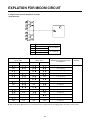
EXPLATION FOR MICOM CIRCUIT
2. Compensation circuit for temperature at freezer
(1) GC-P227/L227
Temperature compensation in CUT
Compensation
for too warm
JCR3
JCR4
JCR1
+1 °C [+1.8 °F]
JCR2
+1 °C [+1.8 °F]
JCR3
-1 °C [-1.8 °F]
JCR4
-1 °C [-1.8 °F]
Compensation
for too cold
JCR1
JCR2
+2 °C [+3.6 °F]
-2 °C [-3.6 °F]
Temperature compensation value
at refrigerator
Remarks
0 °C (In shipment from factory)
CUT
-1 °C [-1.8 °F]
CUT
-1 °C [-1.8 °F]
CUT
+1 °C [+1.8 °F]
CUT
CUT
CUT
-2 °C [-3.6 °F]
CUT
CUT
CUT
CUT
+2 °C [+3.6 °F]
0 °C [0 °F]
CUT
CUT
CUT
CUT
CUT
CUT
CUT
+1 °C [+1.8 °F]
0 °C [0 °F]
0 °C [0 °F]
CUT
0 °C [0 °F]
CUT
CUT
-1 °C [-1.8 °F]
CUT
CUT
CUT
+1 °C [+1.8 °F]
CUT
CUT
CUT
0 °C [0 °F]
u This circuit allows adjustment of the set temperature for compensation by changing jumpers at locations JCR1~JCR4.
- 37 -
EXPLATION FOR MICOM CIRCUIT
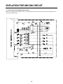
1-13. Communication circuit and connection L/Wire between main PCB and display PCB
The following communication circuit is used for exchanging information between the main MICOM of the Main PCB and the
dedicated MICOM of the LED (LCD) Display PCB.
A bi-directional lead wire assembly between the two boards is required for the display to function properly.
Poor communication occurs if a continuous information exchange fail to continue for more than 2 minutes between main
MICOM of main PCB and LCD (LED) dedicated MICOM for LCD (LED) control of display PCB.
Main PCB
L/Wire FD/H(4-wires)
Display PCB
DC 12V
Main MICOM
LCD(LED) dedicated MICOM
GND
Transmission (error status)
Reception (notch status)
(1) GC-P227/L227
- 38 -
EXPLATION FOR MICOM CIRCUIT
2) Sensor resistance characteristics table
Refrigerator sensor 1&2
Measuring Temperature (°C)
Freezing Sensor
-20 °C
22.3 kΩ
77 kΩ
-15 °C
16.9 kΩ
60 kΩ
-15 °C
13.0 kΩ
47.3 kΩ
-5 °C
10.1 kΩ
38.4 kΩ
0 °C
7.8 kΩ
30 kΩ
+5 °C
6.2 kΩ
24.1 kΩ
+10 °C
4.9 kΩ
19.5 kΩ
+15 °C
3.9 kΩ
15.9 kΩ
+20 °C
3.1 kΩ
13 kΩ
+25 °C
2.5 kΩ
11 kΩ
+30 °C
2.0 kΩ
8.9 kΩ
+40 °C
1.4 kΩ
6.2 kΩ
+50 °C
0.8 kΩ
4.3 kΩ
Defrost sensor, Ambient sensor
u Resistance value allowance of sensor is ±5%.
u When measuring the resistance value of the sensor, allow the temperature of that sensor to stabilize for at least 3 minutes
before measuring. This delay is necessary because of the sense speed relationship.
u Use a digital tester to measure the resistance. An analog tester has to great a margin of error.
u Resistance of the cold storage sensor 1 and 2 shall be measured with a digital tester after separating CON8 of the PWB
ASSEMBLY and the MAIN part.
u Resistance of the freezing sensor shall be measured with a digital tester after separating CON7 of the PWB ASSEMBLY
and the MAIN part.
- 39 -
EXPLATION FOR MICOM CIRCUIT
1-14. Miracle Zone STEPPING MOTOR / Display
Miracle zone stepping motor damper is same as 1-8 stepping motor operation circuit and the miracle zone display turns on
only when the R-door opens.
- 40 -
ICEMAKER AND DISPENSER WORKING PRINCIPLES AND REPAIR
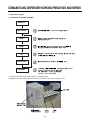
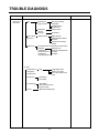
1. Operation Principle
1-1. Operation Principle of Icemaker
Power On
Start Position
Icemaking
Mode
Harvest
Mode
Fill
¥ Adjusts EJECTOR to
Start Position with power on.
¥ Waits until water becomes ice after starting the
icemaking operation.
¥ Runs MOTOR to drop ice from the tray into the ICE BIN.
(During harvest mode, check if the ice bin is full)
¥ Performs
Ice Making Mode after supplying water by operating
the SOLENOID in ICE VALVE.
Park Position
Test Mode
¥ With the detect lever, checks if the ICE BIN is full.
¥ To operate LINE and SERVICE, press and hold the
amount selection button for 3 seconds.
The icemaker will run through 3 stages:
Harvest
Fill
Icemaking.
1. Turning the Icemaker switch off (O) stops the ice making function.
2. Setting the Icemaker switch to OFF and then turning it back on will reset the icemaker control.
- 41 -
Water
ICEMAKER AND DISPENSER WORKING PRINCIPLES AND REPAIR
2. ICEMAKER FUNCTIONS
2-1. Start Position
1. After POWER OFF or power outage, check the EJECTOR's position with MICOM initialization to restart.
2. How to check if it is in place:
- Check HIGH/LOW signals from HALL SENSOR in MICOM PIN.
3. Control Method to check if it is in place:
(1) EJECTOR is in place,
- It is an initialized control, so the mode can be changed to icemaking mode.
(2) EJECTOR isn't in place:
A. If EJECTOR is back in place within 2 minutes with the motor on, it is being initialized. If not, go to Step B.
B. Control the heater using the temperature sensor until the EJECTOR reaches the correct location.
2-2. Icemaking Mode
1. Icemaking refers to the freezing of supplied water in the ice tray. Complete freezing is assured by measuring the
temperature of the Tray with Icemaking SENSOR.
2. Icemaking starts after completion of the water fill operation.
3. The Ice Making function is completed when the sensor reaches 19°F (-7°C), 55 minutes after starting.
NOTE : After Icemaker Power is ON, the Icemaker heater will be on for test for 6 sec.
2-3. Harvest Mode
1. Harvest (Ice removing) refers to the operation of dropping ices into the ice bin from the tray when icemaking has
completed.
2. Harvest mode:
(1) The Heater is ON for 30 seconds, then the motor starts.
(2) The feeler arm senses the quantity of ice in the ice bin while rotating with the EJECTOR.
A. ice bin is full : The EJECTOR stops (heater off).
B. ice bin is not full : The EJECTOR rotates twice to open for ice.
If the EJECTOR does not rotate once within 5 minutes in B mode, separate heater control mode starts operating to
prevent the EJECTOR from being constrained. (It is recommended that the user open for ice to return to normal mode.)
2-4. Fill/Park Position
1. Once a normal harvest mode has been completed, the water solenoid will be activated.
2. The amount of water is adjusted by pressing the Fill Key repeatedly. This changes the time allowed for fill as illustrated in
the table below.
Water supply amount TABLE
STAGE
TIME TO SUPPLY
1
5 sec.
2
5.5 sec.
INDICATIONS
REMARKS
The water amount will vary depending
on the water control switch setting, as
(FIRST STAGE)
well as the water pressure of the
connected water line.
3
6 sec.
- 42 -
ICEMAKER AND DISPENSER WORKING PRINCIPLES AND REPAIR
2-5. Function TEST
1. This is a forced operation for TEST, Service, cleaning, etc. It is operated by pressing and holding the Water amount selection
button for 3 seconds.
2. The test works only in the Icemaking Mode. It cannot be entered from the Harvest or Fill mode. (If there is an ERROR, it
can only be checked in the TEST mode.)
3. Caution! If the test is performed before water in the ice tray is frozen, the ejector will just pass through the water. When
the Fill mode begins (Stage 4), unless the water supply has been shut off, added water will overflow into the ice bin. If the
control doesn’t operate normally in the TEST mode, check and repair as needed.
4. After water is supplied, the normal CYCLE is followed: icemaking → Harvest → Fill → Park Position.
5. After Stage 5 is completed, the Ice Maker returns to MICOM control. The time needed to supply water resets to the pretest setting.
6. This icemaker function test takes about 90 seconds in case, there aren’t ices in the ice tray. If there are ices in the ice
tray, it can take more than 90 seconds.
Diagnosis TABLE
STAGE
ITEMS
INDICATOR
REMARKS
1
HEATER
Five seconds after heater starts, a
heater will go off if the temperature by
sensor is higher than 10°C
2
MOTOR
Five seconds after heater starts, you
can confirm that a motor is moving.
3
HALL IC I
(detection of
position)
After the icemaker detects that ice has been
made, the motor and heater are off but on
standby until the cycle is cancelled.
4
HALL IC II
(detection of
position)
You can confirm HALL IC detection of
position.
5
VALVE
6
Reset
Two seconds after detection of initial
position, you can confirm that valve is on.
Five seconds after fifth stage is completed,
The icemaker resets to initial status.
Return to Status prior to
TEST MODE
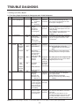
3. Defect diagnosis function
3-1. ERROR CODES shown on Icemaker water supply control panel
NO
DIVISION
1
Normal
2
Icemaking
Sensor
malfunction
INDICATOR
CONTENTS
REMARKS
None
Display switch
operates properly
Open or short-circuited wire
Make sure that the wire
on each sensor is
connected.
Mark time to
supply
ERROR indicators in table can be checked only in TEST mode.
- 43 -
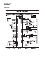
CIRCUIT
(1) GC-P227/L227
- 44 -
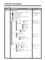
TROUBLE DIAGNOSIS
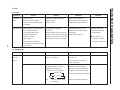
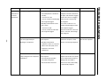
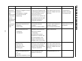
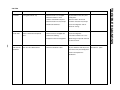
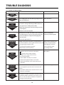
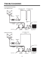
1. Trouble Shooting
CLAIMS.
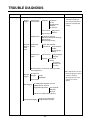
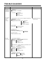
1. Faulty start
CAUSES AND CHECK POINTS.
HOW TO CHECK
* Measuring instrument :
Multi tester
1) No power on outlet.
2) No power on cord.
Bad connection between adapter and outlet. (faulty adapter)
The Inner diameter of adapter.
The distance between holes.
The distance between terminals.
The thickness of terminal.
Bad connection between plug and adapter (faulty plug).
The distance between pins.
Pin outer diameter.
3) Shorted start circuit.
No power on Disconnected copper wire.
power cord.
Power cord is disconnected.
Faulty soldering.
Internal electrical short.
Loose contact.
- Large distance between
male terminal.
- Thin female terminal.
Faulty terminal contact.
■ Check the voltage.
If the voltage is within ±85%
of the rated voltage, it is OK.
■ Check the terminal
movement.
■ Check both terminals of
power cord.
Power conducts : OK.
No power conducts : NG
Terminal disconnected.
Bad sleeve assembly.
Disconnected.
O.L.P is off.
Weak connection.
Short inserted cord length.
Worn out tool blade.
Capacity of O.L.P is small.
Characteristics of O.L.P is bad.
Bad connection.
Power is
Inner Ni-Cr wire blows out.
disconnected.
Bad internal connection.
Faulty terminal caulking (Cu wire is cut).
Bad soldering.
■ Check both terminals of
O.L.P.
If power conducts : OK.
If not : NG.
No electric power on compressor. - Faulty compressor.
Faulty PTC.
Power does not conduct. - Damage.
Bad characteristics. - Initial resistance is big.
Bad connection with Too loose.
compressor.
Assembly is not possible.
Bad terminal connection.
4) During defrost.
Start automatic defrost.
Cycle was set at defrost when the refrigerator
was produced.
- 45 -
■ Check the resistance of both
terminals.
At normal temperature 6 :
OK.
If disconnected : ∞.
TROUBLE DIAGNOSIS
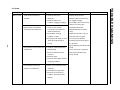
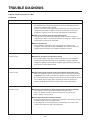
CLAIMS.
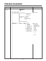
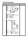
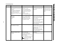
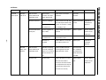
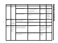
2. No cooling.
CAUSES AND CHECK POINTS.
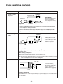
2) Refrigeration system is clogged.
Moisture
clogged.
Residual moisture
in the evaporator.
Air Blowing.
Not performed.
Too short.
Impossible moisture
confirmation.
Low air pressure.
Leave it in the air.
Caps are missed.
No electric
power on
thermostat.
HOW TO CHECK
■ Check the clogged
evaporator by heating (as
soon as the cracking sound
begins, the evaporator start
freezing)
During rest time.
After work.
Residual moisture.
Not dried in the compressor.
Elapsed more than 6 months after drying
Caps are missed.
No pressure when it is open.
Insufficient drier
capacity.
Dry drier - Drier temperature.
Leave it in the air.
Check on package
condition.
Good storage after
finishing.
Residual moisture
in pipes.
Caps are missed.
During transportation.
During work.
Air blowing. Not performed.
Performed.
Too short time.
Low air pressure.
Less dry air.
Moisture penetration - Leave it in the air. - Moisture penetration.
into the refrigeration oil.
■ The evaporator does not cool
from the beginnig (no evidece
of misture attached).
The evaporator is the same
as before even heat is
applied.
Short pipe insert.
Weld joint
clogged.
Pipe gaps.
Too large.
Damaged pipes.
Too much solder.
The capillary tube inserted depth. - Too much.
Drier cloggeing.
Capillary tube melts. - Over heat.
Clogged with foreign materials.
Desiccant powder.
Weld oxides.
Drier angle.
Reduced cross section by cutting. - Squeezed.
Foreign material clogging.
Compressor cap is disconnected.
Foreign materials are in the pipe.
- 46 -
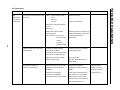
TROUBLE DIAGNOSIS
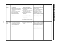
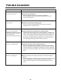
CLAIMS.
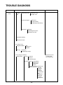
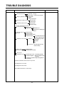
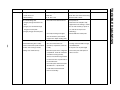
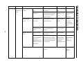
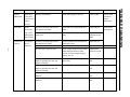
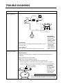
3. Refrigeration
is weak.
CAUSES AND CHECK POINTS.
1) Refrigerant Partly leaked.
Weld joint leak.
Parts leak.
2) Poor defrosting capacity.
Drain path (pipe) clogged.
HOW TO CHECK
Inject P/U into drain hose.
Foreign materials
penetration.
■ Check visually.
Inject through the
hole.
Seal with drain.
P/U lump input.
Screw input.
Other foreign materials
input.
Cap drain is not disconnected.
Defrost heater does not
generate heat.
Parts
disconnected.
Heater
Sheath
Wire is cut.
- Lead wire.
- Heating wire.
- Contact point
between heating and
electric wire.
Dent by fin evaporator.
Heating wire is corroded
- Water penetration.
Bad terminal connection.
■ Check terminal
Conduction: OK.
No conduction: NG.
If wire is not cut, refer to
resistance.
P=Power
V=Voltage
R=Resistance
V2
P= —
R
V2
R= —
P
- 47 -
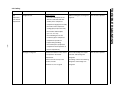
TROUBLE DIAGNOSIS
CLAIMS.
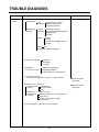
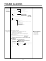
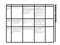
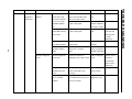
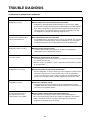
3. Refrigeration
is weak.
CAUSES AND CHECK POINTS.
Residual
frost.
Weak heat from heater.
HOW TO CHECK
Sheath Heater - rated.
Heater plate - rated.
Too short defrosting time.
Defrost Sensor.
- Faulty characteristics.
Seat-D(missing, location. thickness).
Structural fault.
Gasket gap.
Air inflow through the fan motor.
Bad insulation of case door.
No automatic defrosting.
Defrost does not return.
3) Cooling air leak.
Bad gasket adhestion
Door sag.
Gap.
Bad attachment.
Contraction.
Bad adhesion.
Weak binding force at hinge.
4) No cooling air circulation.
Faulty fan motor.
Fan motor.
Door switch.
Self locked.
Wire is cut.
Bad terminal contact.
Faults.
Contact distance.
Button pressure.
Melted contact.
Contact.
Refrigerator and freezer switch reversed.
Button is not pressed. Poor door
attachment.
Door liner
(dimension).
Contraction inner
liner.
Misalignment.
Bad terminal
connection.
P/U liquid leak.
- 48 -
■ Check the fan motor
conduction: OK.
No conduction: NG.
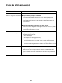
TROUBLE DIAGNOSIS
CLAIMS.
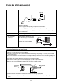
3. Refrigeration
is weak.
CAUSES AND CHECK POINTS.
HOW TO CHECK
4) No cooling air circulation.
Faulty fan motor.
Fan is
constrained.
Fan shroud contact. - Clearance.
Damping evaporator contact.
Accumulated residual frost.
Small cooling air
discharge.
Insufficient
motor RPM
Fan overload. - Fan misuse.
Bad low termperature RPM characteristics.
Rated power misuse.
Low voltage.
Faulty fan.
Shorud.
Fan misuse.
Bad shape.
Loose connection. - Not tightly connected.
Insert depth.
Bent.
Ice and foreign materials on rotating parts.
5) Compressor capacity.
Rating misuse.
Small capacity.
Low valtage.
6) Refrigerant
too much or too little.
Malfunction of charging cylinder.
Wrong setting of refrigerant.
Insufficient compressor. - Faulty compressor.
7) Continuous operation
- No contact of temperature controller. - Foreign materials.
8) Damper opens continuously.
Foreign materials
P/U liquid dump.
jammed.
EPS water sediment.
Screw.
Failed sensor. - Position of sensor.
Characteristics
Bad characteristics of its own temperatue.
of damper.
Parts misuse.
Charge of temperature - Impact.
characteristics.
9) Food storing place. - Near the outlet of cooling air.
- 49 -
■ Check visually after
disassembly.
■ Check visually after
disassembly.
TROUBLE DIAGNOSIS
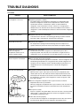
CLAIMS.
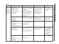
4. Warm
refrigerator
compartment
temperature.
CAUSES AND CHECK POINTS.
1) Colgged cooling path.
P/U liquid leak.
Foreign materials. –– P/U dump liquid.
2) Food storate.
5. No automatic
operation.
(faulty
contacts.)
Store hot food.
Store too much at once.
Door open.
Packages block air flow.
1) Faulty temperature sensor in freezer or refrigerator compartment.
Faulty contact.
Faulty temperature characteristics.
2) Refrigeration load is too much.
3) Poor insulation.
4) Bad radiation.
Food.
Too much food.
Hot food.
Frequent opening and closing.
Cool air leak.
Poor door close. – Partly opens.
High ambient temperature.
Space is secluded.
5) Refrigerant leak.
6) Inadequate of refrigerant.
7) Weak compressor discharging power.
Different rating.
Small capacity.
8) Fan does not work.
9) Button is positioned at "strong."
6. Dew and
ice formation.
HOW TO CHECK
1) Ice in freeezer compartment.
External air inflow. –– Rubber motor assembly direction(reverse).
Door opens
Weak door closing power.
but not closes.
Stopper malfunction.
Door sag.
Food hinders door closing.
Gap around gasket. –– Contraction, distortion, loose, door twisted, corner not
fully inserted.
Food vapor. –– Storing hot food. –– Unsealed food.
2) Condensation in the refrigerator compartment.
Insufficient closing.
Door opens
but not closes.
Door sag.
Food hinders door closing.
Gasket gap.
3) Condensation on liner foam.
Cool air leak
Not fully filled.
and transmitted.
Toop table part.
Out plate R/L part.
Flange gap. –– Not sealed.
Gasket gap.
- 50 -
■ Inspect parts measurements
and check visually.
TROUBLE DIAGNOSIS
CLAIMS.
6. Dew and
ice formation.
CAUSES AND CHECK POINTS.
HOW TO CHECK
4) Dew on door.
Dew on the duct door. - Duct door heater is cut.
Dew on the dispense
Recess Heater is cut.
recess.
Duct door is open. / Foreign material clogging.
Dew on the door surface.
Dew on the
gasket surface.
Not fully filled.
Surface.
Cormer.
P/U liquid contraction.
Liquid shortage.
Liquid leak.
Bad wing adhesion.
Wing sag(lower part).
Door liner shape mismatch.
Corner.
Too much notch.
Broken.
Home Bar heater is cut.
5) Water on the floor.
Dew in the refrigerator compartment.
Defrosted water overflows.
Clogged discharging hose.
Discharging hose
Evaporation tray located at wrong place.
location.
Tray drip.
Damaged.
Breaks, holes.
Small Capacity.
Position of drain.
7. Sounds
1) Compressor compartment operating sounds.
Compressor sound
Sound from machine itself.
inserted.
Sound from vibration.
Restrainer.
Rubber Too hard.
seat.
Distorted.
Aged.
Burnt.
Stopper. Bad Stopper Not fit
assembly.
(inner
diameter
of stopper).
Tilted.
Not
Compressor base not connected.
Bad welding compressor stand(fallen).
Foreign materials in the compressor
compartment.
O.L.P. sound.
Capacitor noise.
Pipe sound.
Chattering sound.
Insulation paper vibration.
Pipe contacts each other. – Narrow interval.
No vibration damper. Damping rubber-Q.
Damping rubber-S.
Capillary tube unattached.
- 51 -
TROUBLE DIAGNOSIS
CLAIMS.
7. Sounds
CAUSES AND CHECK POINTS.
1) Compressor compartment operating sounds.
Transformer sound.
Its own fault. –– Core gap.
Bad connection. –– Correct screw connection.
Drip tray vibration sound. Bad assembly.
Distortion.
Foreign materials inside.
Back cover machine sound.
Condenser drain sound.
Bad connection.
Partly damaged.
Not connected.
Bad pipe caulking.
2) Freezer compartment sounds.
Fan motor sound.
Normal operating sound.
Vibration sound.
Aged rubber seat.
Bad torque for assembling motor
bracket.
Sounds from fan
contact.
Fan guide contact.
Shroud burr contact.
Damping evaporator contact.
Residual frost contact.
Poor treatment Cord heater.
Narrow evaporator interval.
Unbalance fan sounds.
Unbalance.
Surface machining conditions.
Fan distortion.
Misshappen.
Burr.
Ice on the fan. –– Air intake (opposite to motor
rubber assembly.)
Motor shaft
contact sounds.
Resonance.
Evaporator noise.
Supporter disorted.
Tilted during motor assembly.
Evaporator pipe contact. –– No damping evaporator.
Sound from refrigerant. –– Stainless steel pipe shape in
accumulator.
Sound from fin evaporator and pipe during expansion
and contraction.
3) Bowls and bottles make contact on top shelf.
4) Refrigerator roof contact.
5) Refrigerator side contact.
6) Insufficient Lubricants on door hinge.
- 52 -
HOW TO CHECK
TROUBLE DIAGNOSIS
CLAIMS.
8. Faulty lamp
(freezer and
refrigerator
compartment).
CAUSES AND CHECK POINTS.
1) Lamp problem.
2) Bad lamp assembly.
3) Bad lamp socket.
Disconnection.
Short.
HOW TO CHECK
Filament blows out.
Glass is broken.
Not inserted.
Loosened by vibration.
Bad soldering.
Bad rivet contact.
Water penetration.
Low water
level in tray.
Bad elasticity of contact.
Bad contact(corrosion).
4) Door switch.
Its own defect.
Refrigerator and freezer switch is reversed.
Travlel distance.
Bad connection.
Bad terminal contact.
P/U liquid leak..
9. Faulty internal
voltage(short).
1) Lead wire is damaged.
Wire damage when assembling P.T.C. Cover.
Outlet burr in the bottom plate.
Pressed by cord heater. lead wire, evaporator pipe.
2) Exposed terminal.
Compressor Compartment terminal. - Touching other
components.
Freezer compartment terminal. - Touching evaporator pipe.
3) Faulty parts.
Transformer.
Coil contacts cover.
Welded terminal parts contact cover.
Compressor.
Bad coil insulation.
Plate heater.
Melting fuse.
Sealing is broken.
Moisture penetration.
Cord heater.
Pipe damaged.
Moisture penetration.
Bad sealing.
Sheath heater.
- 53 -
■ Connect conduction and
non-conduction parts and
check with tester.
Conduction: NG.
Resistance∞: OK.
TROUBLE DIAGNOSIS
CLAIMS.
10. Structure,
appearance
and others.
CAUSES AND CHECK POINTS.
1) Door foam.
Sag.
Weak torque of
hinge connection.
Bolt is loosened during
transportaion.
Not tightly fastened.
Screw worn out .
Adhesion surface.
Weak gasket
adhesion.
Fixed tape.
Not well fixed.
Noise during
operation.
Hinge interference.
Malfunction.
Not closed Interference between door liner and inner liner.
Refrigerator
Stopper worn out.
compartment is
Bad freezer compartment door
opened when freezer
assembly.
compartment is
No stopper.
closed (faulty stopper).
2) Odor.
Temperature of
refrigerator
compartment.
High.
Bigger door foam.
Hinge-Pin tilted-Poor flatness.
No washer.
No grease and not enough
quantity.
Faulty damper control.
Button is set at "weak".
Door is open (interference by
food).
Deodorizer.
No deodorizer.
Poor capacity.
Food Storage.
Seal condition.
Store special odorous food.
Long term storage.
Others.
Odors from chemical procucts.
- 54 -
HOW TO CHECK
2-1. Power
Problems
Causes
Checks
Measures
No power on
- Power cord cut.
- Check the voltage with tester.
-Replace the components.
outlet.
- Faulty connector insertion.
- Check visually.
-Reconnect the connecting parts.
- Faulty connection between plug
- Check visually.
- Reconnect the connecting parts.
- Check the fuse with tester
- Find and remove the cause of
Remarks
and adapter.
Fuse blows out. - Short circuit by wrong connection.
- Low voltage products are
connected to high voltage.
- Short circuit by insects.
- Electricity leakage.
- High voltage.
or visually.
- Check the input volt are with tester
- Replace with rated
problem(ex. short, high voltage,
fuse after confirming
low voltage).
its specification.
(between power cord and products). - Replace with rated fuse.
■ If fuse blowns out
- Check the resistance of power cord
with testerf (if it is 0Ω, it is shorted).
frequently, reconfirm
- Short circuit of components
the cause and prevent.
- 55 -
(tracking due to moisture and dust
penetration).
2-2. Compressor
Problems
Compressor
Causes
- Faulty PTC.
does not
Checks
- Check the resistance.
Vlaue:∞ is defective.
operate.
Measures
- If resistance is infinite, replace it
with new one.
- If it is not infinite, it is normal.
- Check other parts.
- Compressor is frozen.
- If compressor assembly parts are
- During forced operation:
normal(capacitor, PTC, OLP),
- Operates: Check other parts.
apply power directly to the
- Not operate: Replace the frozen
compressor to force operation.
Auxiliary winding
compressor with new one, weld,
evacuate, and recharge refrigerant.
Main winding
Power
OLP
It starts as soon as it is
contacted.
• Refer to weld repair procedures.
Remarks
TROUBLE DIAGNOSIS
2. Faults
Problems
Causes
Checks
High
Poor cool air circulation due to faulty - Lock –– Check resistance with a
temperature
fan motor.
Measures
Remarks
- Replace fan motor.
tester.
in the freezer
0Ω: short.
compartment.
∞Ω: cut.
- Reconnect and reinsert.
- Rotate rotor manually and check
rotation.
- Wire is cut.
- Bad terminal contact: Check
terminal visually.
- Maintain clearance and remove ice
(Repair and/or replace shroud if fan
- Fan constraint. – Fan shroud
contact: Confirm
is constrained by shroud
deformation).
visually.
– Fan icing:
- 56 -
Confirm visually.
Faulty fan motor due to faulty door
switch operation.
- Iced button (faulty) operation:
Press button to check
- Confirm icing causes and repair.
- Replace door switch.
- Faulty button pressure and contact:
Press button to check operation.
- Door cannot press door switch
button: Check visually.
- Door sag: fix door.
- Door liner bent:replace door or
attach sheets.
Bad radiation conditions in
compressor compartment.
- Check the clearance between the
refrigerator and wall (50 mm in
minimum).
- Check dust on the grill in
compressor compartment.
- Keep clearance between
- The fan may be
refrigerator and walls (minimum
broken if cleaning
50mm).
performs while the
- Remove dust and contaminants
from grill for easy heat radiation.
- Check dust on the coils condenser. - Remove the dust with vacuum
cleaner from the coils condenser
while the refrigerator is off.
refrigerator is on.
TROUBLE DIAGNOSIS
2-3. Temperature
Problems
High
Causes
Refrigerant leak.
temperature
Checks
Measures
Check sequence
Weld the leaking part, recharge the
1. Check the welded parts of the
refrigerant.
in the freezer
drier inlet and outlet and drier
compartment.
auxiliary in the compressor
Remarks
Drier must be replaced.
compartment (high pressure side).
2. Check the end of compressor
sealing pipe (low pressure side).
3. Check silver soldered parts.
(Cu + Fe / Fe + Fe).
4. Check bending area of wire
condenser pipe in compressor
compartment (cracks can
happen during bending).
- 57 -
5. Check other parts (compressor
compartment and evaporators in
freezer compartment).
Shortage of refrigerant.
Check frost formation on the surface - Find out the leaking area, repair,
of evaporator in the freezer
evacuate, and recharge the
compartment.
refrigerant.
- If the frost forms evenly on the
surface, it is OK.
- If it does not, it is not good.
- No leaking, remove the remaining
refrigerant, and recharge new
refrigerant.
Drier must be replaced.
TROUBLE DIAGNOSIS
2-4. Cooling
High
Causes
Cycle pipe is clogged.
temperature in
Checks
Check sequence.
1. Check temperature of condenser
the freezer
compartment.
Measures
- Heat up compressor discharging
Direr must be replaced.
weld joints with touch, disconnect
manually.
the pipes, and check the clogging.
If it is warm, it is OK.
Remove the causes of clogging,
If it is not, compressor discharging
weld, evacuate, and recharge
joints might be clogged.
the refrigerant.
2. Manually check whether hot line
Remarks
- If it's warm, it's OK. If it's not,
pipe is warm.
condenser discharging line weld
If it is warm, it's OK.
joints might be clogged.
If it is not, condenser outlet weld
Disconnect with torch, remove the
joints might be colgged.
causes, evacuate, and recharge
seal refrigerant.
- 58 -
Leak at loop pipe weld joint
Check sequence.
Replace the compressor, weld,
(discharge) in compressor.
1. Manually check whether
evacuate, and recharge refrigerant.
condenser is warm, It is not warm
and the frost forms partly on the
evaporator in the freezer
compartment.
Faulty cooling fan in the compressor
compartment.
Check sequence.
- Replace if motor does not operate.
1. Check cooling fan operation.
- If fan is disconnected, check fan
2. Check that cooling fan is
disconnected from the motor.
damage and reassemble it.
■ Refer to fan motor disassembly
and assembly sequence.
Drier must be replaced.
TROUBLE DIAGNOSIS
Problems
Problems
No defrosting.
Causes
Heater does not generate heat as
the heating wire is cut or the circuit
is shorted.
1) Heating wire is damaged when
inserting into the evaporator.
2) Lead wire of heater is cut.
3) Heating wire at lead wire contacts
is cut.
Sucking duct and discharging hole
are clogged:
1. Impurities.
2. Ice.
Checks
1. Check the resistance of heater.
0Ω: Short. ∞Ω: Cut.
Tens to thousands Ω: OK.
Measures
Heating wire is short and wire is cut.
Seal the lead wire with
• Parts replacement: Refer to parts
insulation tape and heat
explanations.
2. Check the resistance between
housing terminal and heater
repair.
0Ω: Short. ∞Ω: Cut.
Tens to thousands Ω: Short.
1. Confirm foreign materials. In case 1) Push out impurities by inserting
of ice, insert the copper line
copper wire.(Turn off more than
through the hole to check.
3hours and pour in hot water if
(check drains outside).
frost is severe.)
2) Put in hot water to melt down frost.
3) Check the water outlet.
- 59 -
4) Push the heater plate to sucking
duct manually and assemble the
disconnected parts.
Gap between Sucking duct and
1. Confirm in the Sucking duct.
Heater plate(Ice in the gap).
1) Turn off the power, confirm
impurities and ice in the gap, and
supply hot water until the ice in the
gap melts down.
2) Push the Heater plate to drain
bottom with hand and assemble
the disconnected parts.
Wrong heater rating (or wrong
1. Check heater label.
Faults:replace.
assembly).
2. Confirm the capacity after
- How to replace: Refer to main parts.
substituting the resistance value
into the formula.
V2 (V: Rated voltage of user country)
P= ––
R (R: Resistance of tester[Ω])
Compare P and lavel capacity.
Tolerance: ±7%
contraction tube if the cut
lead wire is accessible to
surface.
2. Put hot water into the drain
Remarks
TROUBLE DIAGNOSIS
2-5. Defrosting failure
No defrosting
Causes
Melting fuse blows out.
Checks
- Check melting fuse with tester. -
1) Lead wire is cut.
If 0Ω: OK.
2) Bad soldering.
If ∞Ω: wire is cut.
Ice in the Sucking duct.
1. Check the inner duct with mirror.
1) Icing by foreign materials in the
Measures
Faullty parts: parts replacement.
- Check wire color when maeasuring
resistance with a tester.
1) Turn power off.
2) Raise the front side(door side),
duct.
support the front side legs, and let
2) Icing by cool air inflow through
the ice melt naturally. (If power is
the gap of heater plate.
on, melt the frost by forced
3) Icing by the gap of heater plate.
defrosting.)
2. Check by inserting soft copper
3) Reassemble the heater plate.
wire into the duct (soft and thin
copper not to impair heating wire).
Bad cool air inflow and discharge,
1. Turn on power, open or close the
1) Check the faulty connector of
- 60 -
and bad defrosting due to faulty
door, check that motor fan
housing and reassemble wrongly
contact and insertion (bad connector
operates (If it operates, motor fan
assembled parts.
insertion into housing of heater,
is OK).
melting, fuse and motor fan).
2. Disconnect parts in the refrigerator
compartment, check the connection
around the housing visually,
defrost, and confirm heat generation
on the heater. Do not put hands on
the sheath heater.
3. Check the parts which have faults
described in 1, 2 (mechanical
model: disconnect thermostat
from the assembly).
2) If the parts are very damaged,
remove the parts and replace it
with a new one.
Remarks
TROUBLE DIAGNOSIS
Problems
Problems
Causes
Checks
Icing in the
1) Bad circulation of cool air.
- Check the food is stored properly
refrigerator
- Clogged intake port in the
(check discharge and intake port
compartment.
refrigerator compartment.
- Damper icing.
- Sealing is not good.
- Pipe icing.
- Too much food is stored and clogs
- Discharging
pipe icing.
the discharge port.
- Bad defrosting.
are clogged).
- Check icing on the surface of
baffle and cool air path (pipe) after
dissembling the container box.
- Check icing at intake ports of
Measures
- Be acquainted with how to use.
Remarks
- Check the defrost
- Sealing on connecting parts.
related parts if problem
- Check the damper and replace
is caused by faulty
it if it has defects.
defrosting.
- Check defrost. (After forced
defrosting, check ice in the
evaporator and pipes.)
freezer and refrigerator
compartment.
2) Faulty door or refrigerator
compartment.
- Check gasket attached conditions.
- Check door assembly conditions.
- Faulty gasket.
- Correct the gasket attachment
conditions and replace it.
- Door assembly and replacement.
- Replacement should
be done when it
cannot be repaired.
- Faulty assembly.
- 61 -
3) Overcooling in the refrigerator
compartment.
- Faulty damper in the refrigerator
compartment.
- Check refrigerator compartment
- Replace faulty parts.
is overcooled (when button
pressed on "weak").
- Check parts are faulty.
- Faulty MICOM (faulty sensor)
4) Bad defrosting
- Heater wire is cut.
- Defective defrost sensor.
- Defrosing cycle.
- Check frost on the evaporator
after dissembling shroud and fan
grille.
- Check parts related to defrosting.
- Check defrosting. (Check ice on the
evaporator and pipe.)
- Check ice on intake port of freezer
- Moisture cannot frost
on the evaporator but
can be sucked into the
refrigerator, being
and refrigerator compartment.
condensed and iced,
interferes with cool air
circulation, and
suppresses sublimation.
5) Customers are not familiar with
this machine.
- Door opens.
- High temperature, high moisture,
and high load.
- Check food interferes with door
closing.
- Check ice on the ceilings.
- Be acquainted with how to use.
TROUBLE DIAGNOSIS
2-6. Icing
Causes
Ice in the freezer 1) Bad cooling air circulation.
compartment.
- Surface of fan
grille.
- Intake port is colgged in the freezer
compartment.
- Discharging port is Clogged.
- Wall of freezer - Too much food is stored.
compartment.
- Bad defrosting.
- Cool air
Checks
- Check food storage conditions
visually.(Check clogging at intake
and discharging port of cooling air.)
- Check food occupation ratio in
Measures
- Be acquainted with how to use.
- Check defrost (Check ice on the
Remarks
- Check the parts related
to defrosting if the
evaporator and pipes after forced
problem is caused by
defrosting).
the faulty defrosting.
volume(Less than 75%).
- Check frost on the evaporator after
dissembling shroud and fan grille.
discharging port.
- Check icing at intake port of
- Basket(rack)
refrigerator compartment.
area.
- Food surface. 2) Bad freezer compartment door
- Icing in the
shute.
- Faulty gasket
- Check gasket attachment
conditions.
- Correct the gasket attachement
conditions and replace it.
- 62 -
- Faulty assembly
- Check door assembly conditions.
- Door assembly and replacement.
3) Over freezing in the freezer
- Refrigerator operates pull down.
-Replace defective parts.
compartment.
- Faulty MICOM.
(Check if it is operated
intermittently)
- The Temperature of freezer
compartment is satisfactory, but
over freezing happens in the
refrigerator compartment even
though the notch is set at "weak".
4) Bad defrosting.
- Heater wire is cut.
- Faulty defrost sensor.
- Defrosting cycle
5) User is not familiar with how to
use.
- Door opens.
- High moisture food(water) is stored.
- Check frost on the evaporator after - Check parts related to defrosting.
dissembling shroud and grille.
- Check ice on the intake port in the
refrigerator compartment.
- Check food holds door open.
- Check ice on the ice tray.
- Check defrosting.(Check ice on the
evaporator and pipes after forced
defrosting.)
- Be acquainted with how to use.
- Replace when it can not
be repaired.
TROUBLE DIAGNOSIS
Problems
Problems
"Whizz" sound
Causes
1. Loud sound of compressor
operation.
Checks
1.1 Check the level of the
refrigerator.
1.2 Check the rubber seat
conditions (sagging and aging).
Measures
1) Maintain horizontal level.
2) Replace rubber and seat if they
are sagged and aged.
3) Insert rubber where hand contact
reduces noise in the pipe.
2. Pipes resonat sound which is
connected to the compressor.
2.1 Check the level of pipes
connected to the compressor
and their interference.
2.2 Check rubber inserting
conditions in pipes.
4) Avoid pipe interference.
5) Replace defective fan and fan
motor.
6) Adjust fan to be in the center of
bell mouth of the fan guide.
2.3 Touch pipes with hands or screw 7) Leve a clearance between
-driver (check the change of
interfering parts and seal gaps in
sound).
the structures.
- 63 -
8) Reassemble the parts which make
3. Fan operation sound in the freezer 3.1 Check fan insertion depth and
compartment.
blade damage.
3.2 Check the interference with
structures.
3.3 Check fan motor.
3.4 Check fan motor rubber insertion
and aging conditions.
4. Fan operation sound in the
compressor compartment.
4.1 Same as fan confirmation in the
refrigerator.
4.2 Check drip tray leg insertion.
4.3 Check the screw fastening
conditions at condenser and
drip tray.
sound.
9) Leave a clearance if evaporator
pipes and suction pipe touch
freezer shroud.
Remarks
TROUBLE DIAGNOSIS
2-7. Sound
Causes
Vibration sound. 1. Vibration of shelves and foods in
("Cluck")
the refrigerator.
2. Pipes interference and capillary
tube touching in the compressor.
compartment.
3. Compressor stopper vibration.
4. Moving wheel vibration.
5. Other structure and parts
vibration.
Checks
1-1. Remove and replace the
shelves in the refrigerator
1-2. Check light food and container
on the shelves.
2-1. Touch pipes in the compressore
compartment with hands.
2-2 Check capillary tube touches
cover back.
3-1 Check compressor stopper
vibration.
Measures
1) Reassemble the vibrating parts
and insert foam or cushion where
vibration is severe.
2) Leave a clearance where parts
interfere with each other.
3) Reduce vibration with rubber
and restrainer if it is severe.
(especially, compressor and pipe).
4) Replace compressor stopper if it
vibtates severely.
4-1 Check vibration of front and rear
moving wheels.
5-1 Touch other structures and parts.
- 64 -
Irregular sound. 1. It is caused by heat expansion
("Click").
and contraction of evaporator,
1-1 Check time and place of sound
sources.
1) Explain the principles of refrigeration
and that the temperature difference
shelves, and pipes in the
between operation and defrosting
refrigerator.
can make sounds.
2) If evaporator pipe contacts with other
structures, leave a clearance between
them (freezer shroud or inner case).
Remarks
TROUBLE DIAGNOSIS
Problems
Causes
Checks
Sound "Burping" It happens when refrigerant expands - Check the sound of refrigerant at the
(almost the same at the end of capillary tube.
as animals crying
sound).
initial installation.
Measures
- Check the restrainer attached on the
evaporator and capillary tube weld
- Check the sound when the refrigerator
joints and attach another restrainer.
starts operation after forced defrosting.
- If it is continuous and servere, insert
- Check the restrainer attachment
conditions on the evaporator and
capillary tube weld joints.
capillary tube again (depth:15±3mm)
- Fasten the capillary tube to suction
pipes or detach in the compressor
compartment.
- Explain the principles of freezing
cycles.
Water boiling or
It happens when refrigerant passes
flowing sound.
orifice in accumulator internal pipes by
- 65 -
the pressure difference between
condenser and evaporator.
- Check the sound when compressor is
turned on.
- Check the sound when compressor is
turned off.
- Explain the principles of freezing cycles
and refrigerant flowing phenomenon by
internal pressure difference.
- If sound is servere, wrap the
accumulator with foam and restrainer.
Sound of whistle
When door closes, the internal pressure
when door
of the refrigerator decreases sharply
closes.
below atomosphere and sucks air into
the refrigerator, making the whistle
sound.
- Check the sound by opening and
closing the refrigerator or freezer doors.
- Broaden the cap of discharge hose for
defrosting in the compressor
compartment.
- Seal the gap with sealant between out
and inner cases of hinge in door.
Remarks
TROUBLE DIAGNOSIS
Problems
Problems
Food Odor.
Causes
Food (garlic, kimchi, etc)
Checks
- Check the food is not wrapped.
- Check the shelves or inner
wall are stained with food juice.
- Check the food in the vinyl wraps.
- Chedk food cleanliness.
Measures
Remarks
- Dry deodorizer in the shiny and
windy place.
- Store the food in the closed
container instead of vinyl wraps.
- Clean the refrigerator and set
button at "strong".
Plastic Odor.
Odors of mixed food and plastic
odors.
- Check wet food is wrapped with
plastic bowl and bag.
- It happens in the new refrigerator.
- Clean the refrigerator.
- Persuade customers not to use
plastic bag or wraps with wet food
or odorous foods.
- 66 -
Odor from the
deodorizer.
Odor from the old deodorizer.
- Check the deodorizer odors.
- Dry the deodorizer with dryer and
then in the shiny and windy place.
- Remove and replace the
deodorants.
*Deodorizer : option
TROUBLE DIAGNOSIS
2-8. Odor
Problems
Symptom
Causes
Checks
Measures
Bad PCB
All display
Bad connection
Bad connector
Visual check on connector
Reconnect
electric power.
LCD are off.
between Main PCB
connection from main
connection.
connector.
and display circuit.
PCB to display PCB.
Defective PCB trans.
Remarks
PCB Trans winding is
Check resistance of PCB Trans Replace PCB Trans
Applicable to
cut.
input and output terminals with
model without
or PCB.
PCB Trans temperature a tester. (If resistance is infinity,
fuse is burnt out.
trans winding is cut).
DefectivePCB electric
Defective regulator IC
Check voltage at input/output
circuit parts.
(7812, 7805).
terminals.
dispenser.
Replace regulator.
Refer to electric
circuit in circuit
explanation.
PCB electric terminal
Check fuse in PCB electric
fuse is burnt out.
terminal with a tester.
- 67 -
STR Parts are
Check if STR No. 2 and 3 pins
damaged.
are cut when power is off.
Replace PCB fuse.
Replace parts.
Applicable to
model with
dispenser.
Abnormal
Bad connection
Lead Wire connecting
Check Lead Wire terminals
Reconnect Lead
display LCD
operation
between Main PCB
main PCB and display
connecting Main PCB and
Wire and directly
and display circuit.
PCB is cut or connector
display PCB with a tester.
connect defective
Defective LCD.
terminal connection is
contact terminal to
bad.
Lead Wire.
Defective LCD.
Check if all LCD are on when
Replace display
Refer to display
Main PCB Test switch is
PCB.
circuit in circuit
pressed (or when both freezer
key and power freezer key are
pressed at the same time for
more than one second.)
explanation.
TROUBLE DIAGNOSIS
2-9. Micom
Bad cooling.
Symptom
Causes
Checks
Measures
Freezer
Compressor does
Compressor Lead Wire
Check compressor Lead Wire
Reconnect Lead
temperature is
not start.
is cut.
with a tester.
Wire.
Defective compressor
Measure voltage at PCB CON2
Replace relay(RY1
driving relay.
(3&9) after pressing main PCB
and RY2) or PCB.
high.
Remarks
Refer to load
driving circuit in
test switch once. It is OK if
circuit
voltage is normal.
explanation.
Defective freezer
Defective Freezer
Check resistance of freezer
Replace freezer
Refer to
sensor.
sensor parts.
sensor with a tester.
sensor.
resistance
characteristics
table of sensor in
circuit
- 68 -
Freezer sensor is
Confirm the color of sensor in
Repair main PCB
explanation.
substituted for other
circuits (main PCB sensor
sensor housing
sensor.
housing).
Defective freezer fan
Fan motor lead wire
Check fan motor lead wire
Reconnect lead
motor.
is cut.
with a tester.
wire.
• Defective door switch
Measure the voltage between
• Replace door
(freezer, refrigerator,
PCB power blue line and fan
switch (freezer,
driving circuits in
home bar).
motor after pressing test switch
refrigerator and
circuit
• Defective fan motor.
of Main PCB. If the voltage is
home bar).
explanation.
• Defective fan motor
normal, it is OK.
Refer to load
• Replace fan motor.
driving relay.
Faulty defrost.
Refer to faulty defrost items in trouble diagnosis
Refer to trouble
functions.
diagnosis
function.
TROUBLE DIAGNOSIS
Problems
Bad cooling
Symptom
Causes
Checks
Measures
Wrong
Defective Step Motor
Check Step Motor
Check if Step Motor damper
Reconnect lead
Refrigerator
Damper.
damper motor and
motor and reed switch lead
wire.
reed switch and lead
wire are cut with a tester.
wire are cut. Check
Refer to Step Motor damper
Replace Step Motor
Step Motor damper
in parts repair guide.
damperor refrigerator
temperature.
Remarks
control box Assembly.
part.
Check Step Motor
Refer to Step Motor damper
Replace relay or
damper Motor driving
in parts repair guide.
PCB.
relay in PCB.
Refer to single
motor damper
driving circuits
in circuit
explanation.
- 69 -
Foreign materials in Step Check Step Motor damper
Remove foreign
Motor damper baffles.
baffle visually.
materials.
Ice formation on
Check if Step Motor damper
Replace Step Motor
Step Motor damper
Heater wire is cut with a
damper or refrigerator
baffles.
tester.
control Box Assembly.
Replace refrigerator
Defective refrigerator
Defective refrigerator
Check the resistance of
sensor
sensor parts.
refrigerator sensor with a tester. sensor.
Refer to sensor
resistance
characteristic
table in circuit
explanation.
Refrigerator sensor is
Check the sensor color in the
Repair main PCB
substituted for other
circuit. (main PCB sensor
sensor housing.
sensor.
housing.)
Defective refrigerator
Check if refrigerator sensor
Fix again the
sensor assembly
is not fixed at cover sensor but
refrigerator sensor.
condition.
inner case visually.
TROUBLE DIAGNOSIS
Problems
Bad defrost.
Symptom
Defrost is not
Causes
Defrost lead wire is cut.
working.
Defective defrost driving relay.
Defective defrost sensor parts.
Checks
Measures
Remarks
Check if defrost lead wire is cut with a
Reconnect Lead
tester.
Wire.
Check the voltage of CON2 (1 and 7)
Replace relay (RY 7
Refer to load
with a tester after pressing main
and RY 3) or PCB.
driving conditions
PCB test switch twice.
check in circuit
If the voltage is normal then it is OK.
explanation.
Check the resistance of defrost sensor
Replace defrost
Refer to sensor
with a tester.
sensor.
resistance
characteristic
table of circuit
explanation.
- 70 -
Defective
Buzzer
Defective connecting lead wire from
Check lead wire related to door
buzzer
continuously
main PCB to door switch.
switch with a tester.
rings or door
Defective door switch parts.
Refer to door switch in parts repair
opening alarm
Repair lead wire.
Replace door switch.
guide.
does not work.
Defective
Buzzer does
Key input wire is cut or bad connector
Check input wire with a tester.
Reconnect lead
display button
not ring and
terminal contact in main PCB and
wire and replace or
circuit in circuit
key does not
display PCB connecting lead wire.
directly connect bad
explanation.
sense even
contact terminal to
button is
lead wire.
pressed.
Key is continuously depressed due to
Disassemble frame display and confirm
Adjust or replace
structural interference.
visually.
interfering
structures.
Refer to display
TROUBLE DIAGNOSIS
Problems
Symptom
Causes
Trouble mode indication.
Checks
Check trouble diagnosis function.
Measures
Repair troubles
Remarks
Defective
Buzzer rings
display button.
but key does
indication in
Refer to mode
not sense even
function
button is
explanations.
pressed.
Door Buzzer
Buzzer
Defective connecting lead wire from
Check lead wire associated with door
continuously
main PCB to door switch.
switch.
rings or door
Defective freezer compartment door
Refer to door switch in parts repair
Replace Freezer
opening alarm
switch parts.
guide.
compartment door
does not work.
Repair lead wire.
switch.
- 71 -
Bad water/ice
Ice and water
Defective connecting lead wire from
Check Lead Wire associated with lever
dispenser.
are not
Main PCB to lever switch.
switch with a tester.
dispensed.
Defective lever switch parts
Refer to door switch in parts repair guide. Replace lever switch.
Defective photo coupler IC parts.
Check voltage change at photo coupler
Replace photo
output terminals with lever switch
coupler IC or PCB.
Repair lead wire.
pressed. It is OK if voltage change is
between 0V - 5V.
Defective relay associated with ice
Check relay (RY4, RY5, RY12)
Replace defective
dispense (geared motor, cube and
with a tester.
relay.
Check resistance of parts with a tester.
Replace defective
dispenser solenoid).
Defective parts associated with ice
dispense (geared motor, cube and
parts.
dispenser solenoid).
Defective relay associated with water
Check relay (RY7) with a tester
dispense.
Defective parts associated with water
dispenser.
Replace defective
relay.
Check resistance of parts with a tester.
Check model
with dispenser.
Replace defective
parts.
TROUBLE DIAGNOSIS
Problems
TROUBLE DIAGNOSIS
3. Cooling Cycle Heavy Repair
3-1. The Heavy Repair Standards for Refrigerator with R134a Refrigerant
NO.
1
Items
Pipe and piping
system opening time.
2
Welding.
3
N2 sealed parts.
4
Refrigeration
Cycle.
Unit
Min.
Nitrogen
Pressure.
Confirm N2
leak.
Evacuation
time
Vacuum
degree
Min.
Vacuum
EA
Vacuum
piping
EA
Pipe
coupler
EA
5
Outlet
(Socket)
Plug
Refrigerant weighing.
6
Drier replacement.
7
Leak check.
Torr
EA
Standards
Purposes
Remarks
Pipe:within 1 hour. To protect The opening time should be reduced to a
Comp:within
Moisture
half of the standards during rain and
10 minutes. Penetration. rainy seasons (the penetration of water
Drier:within
into the pipe is dangerous).
20 minutes.
Weld under
To protect - Refet to repair note in each part.
Nitrogen
oxide scale - R134a refrigerant is more susceptible to
atmosphere
formation.
leaks than R12 and requires more care
(N2 pressure:
during welding.
0.1~0.2 kg/cm2)
- Do not apply force to pipes before and
after welding to protect pipe from
cracking.
Confirm air leaking To protect - In case of evaporator parts, if it doesn't
sounds when
moisture
noise when removing rubber cap blow
removing rubber
penetration. dry air or N2 gas for more than 1 min
cap.
use the parts.
Sound:usable
No sound:not usable
More than
To remove
40 minutes.
moisture.
Below 0.03(ref)
Note:Only applicable to the model
equipped with reverse flow protect
plate.
High and low
Vaccum efficiency can be improved by
Pressure sides are
operating compressor during evacuation.
evacuated at the
same time for
models above 200L
Use R134a
To protect The rubber pipes for R12 refrigerant shall
exclusive
mixing of be melted when they are used for R134a
manifold.
mineral and refrigerant(causes of leak).
ester oils.
Use R134a
To protect
cxclusive.
R12 Refrigerant mixing.
R134a exclusive.
R134a exclusive
Use R134a
Do not mix
exclusively.
with R12
Weighing
refrigerant.
allowance:±5g
Note:Winter:-5g
Summer:+5g
-Use R134a exclusively To remove
for R134a refrigerator the moisture
-Use R12 exclusively from pipe.
for R12 refrigerator
-Replace drier whenever
repairing refrigerator
cycle piping.
-Do not use soapy
Detect
water for check.
refrigerant
it may be sucked
leak area.
into the pipe by.
- Do not weight the refrigerant at too hot or
too cold an area.(25°C is adequate.)
- Use copper bombe
Socket:2SV Plug: 2PV R134a
Note:Do not burn O-ring (rubber) during
welding.
-Check oil leak at refrigerant leak area.
Use electronic leak detector if oil leak is
not found.
-The electronic leak detector is very
sensitive to halogen gas in the air. It also
can detect R141b in urethane. Please
practice, therfore, many times before use.
NOTE) Please contact Songso company on +82-53-554-2067 if you have inquiry on heavy repair special facility.
- 72 -
TROUBLE DIAGNOSIS
3-2. Summary Of Heavy Repair
Process
Contents
Tools
Trouble
diagnosis
Remove refrigerant
Residuals
- Cut charging pipe ends and discharge refrigerant from
- Use R134a oil and refrigerant for compressor and drier
Parts
replacement
and welding
Filter, side cutters
drier and compressor.
Pipe Cutter, Gas welder, N2 gas
- Confirm N2 sealing and packing conditions before use.
Use good one for welding and assembly.
- Weld under nitrogen gas atmosphere.(N2 gas pressure:
0.1-0.2kg/cm2).
- Repair in a clean and dry place.
- Evacuate for more than forty minutes after connecting
manifold gauge hose and vacuum pump to high (drier)
Vacuum
Vacuum pump(R134a
exclusively), Manifold gauge.
and low (compressor refrigerant discharging parts)
pressure sides.
- Evacuation Speed:113l/min.
Refrigerant
charging and
charging
inlet welding
- Weigh and control the allowance of R134a bombe in a
charge through compressor inlet
manifold gauge, electronic
(Charge while refrigerator operates).
scales, punching off flier,
- Weld carefully after inlet pinching.
gas welding machine
- Check leak at weld joints.
Electronic Leak Detector,
Minute leak: Use electronic leak detector
Check
refrigerant leak
and cooling
capacity
R134a exclusive bombe(mass
vacuum conditions to be ±5 g with electronic scales and cylinder), refrigerant(R134a)
Driver(Ruler).
Big leak: Check visually or fingers.
Note:Do not use soapy water for check.
- Check cooling capacity
➀ Check radiator manually to see if warm.
➁ Check hot line pipe manually to see if warm.
➂ Check frost formation on the whole surface of the
evaporator.
Compressor
compartment
and tools
arrangement
- Remove flux from the silver weld joints with soft brush
or wet rag.(Flux may be the cause of corrosion and
leaks.)
- Clean R134a exclusive tools and store them in a clean
tool box or in their place.
Transportation
and
installation
- Installation should be conducted in accordance with the
standard installation procedure.(Leave space of more
than 5 cm from the wall for compressor compartment
cooling fan mounted model.)
- 73 -
Copper brush, Rag, Tool box
TROUBLE DIAGNOSIS
3-3. Precautions During Heavy Repair
Items
Precautions
1. Use of tools.
1) Use special parts and tools for R134a.
2. Removal of retained
1) Remove retained refrigerant more than 5 minutes after turning off a refrigerator.
refrigerant.
(If not, oil will leak inside.)
2) Remove retained refrigerant by cutting first high pressure side (drier part) with a nipper and
then cut low pressure side. (If the order is not observed, oil leak will happen.)
Evaporator
Compressor
Drier
2
Low pressure side
Condenser
1 High pressure side
3. Replacement of drier.
1) Be sure to replace drier with R134a only when repairing pipes and injecting refrigerant.
4. Nitrogen blowing
1) Weld under nitrogen atmosphere in order to prevent oxidation inside a pipe.
welding.
5. Others.
(Nitrogen pressure : 0.1~0.2 kg/cm2.)
1) Nitrogen or refrigerant R134a only should be used when cleaning inside of cycle pipes
inside and sealing.
2) Check leakage with an electronic leakage tester.
3) Be sure to use a pipe cutter when cutting pipes.
4) Be careful not the water let intrude into the inside of the cycle.
- 74 -
TROUBLE DIAGNOSIS
3-4. Practical Work For Heavy Repair
Items
Precautions
1. Removal of residual
Evaporator
Low pressure side
refrigerant.
KEYPOINTING
Observe the sequence for
removal of refrigerant.
(If not, compressor oil may
leak.)
Compressor
Drier
Suction
Refrigent
Intake
Release Condenser
High pressure side
1) Remove residual refrigerant more than 5 minutes later after turning off the refrigerator.
( If not, compressor oil may leak inside.)
2) Remove retained refrigerant slowly by cutting first high pressure side (drier part) with a
nipper and then cut low pressure side.
2. Nitrogen blowing
Evaporator
welding.
1
2
1
Drier
Refrigent
Intake
2
Condenser
High pressure side
KEYPOINTING
Welding without nitrogen
blowing produces oxidized
scales inside a pipe, which
affect on performance and
reliability of a product.
When replacing a drier:
Weld and parts by blowing nitrogen(0.1~0.2kg/cm2) to high pressure side after
assembling a drier.
When replacing a compressor:
Weld and parts by blowing nitrogen to the low pressure side.
Note) For other parts, nitrogen blowing is not necessary because it does not produce oxidized
scales inside pipe because of its short welding time.
3. Replacement of drier.
* Unit : mm
+3
12 Filter
0
KEYPOINTING
Be sure to check the
inserted length of capillary
tube when it is inserted. (If
too much inserted, a
capillary tube is clogged by
a filter.)
Inserting a capillary tube
Measure distance with a ruler and put a mark(12+3/-0)on the capillary tube. Insert tube to the
mark, and weld it
- 75 -
TROUBLE DIAGNOSIS
Items
Precautions
4.Vacuum degassing.
Evaporator
Suction pipe
Compressor
Drier
Condenser
3
2
1
Low
pressure
High
pressure
Blue
Yellow
Red
Vaccum
Pump
KEYPOINTING
- If power is applied
during vacuum
degassing, vacuum
degassing shall be
more effective.
Pipe Connection
Connect a red hose to the high pressure side and a blue hose to the
low pressure side.
Vacuum Sequence
Open , valves and evacuate for 40 minutes. Close valve .
- Operate compressor
while charging
refrigerant. (It is
easier and more
certain to do like
this.)
5.Refrigerant charging.
Charging sequence
1) Check the amount of refrigerant supplied to each model after completing vacuum
degassing.
2) Evacuate bombe with a vacuum pump.
3) Measure the amount of refrigerant charged.
- Measure the weight of an evacuated bombe with an electronic scale.
- Charge refrigerant into a bombe and measure the weight. Calculate the weight of
refrigerant charged into the bombe by subtracting the weight of an evacuated bombe.
Indicate the weight of
an evacuated bombe
R134a
KEYPOINTING
- Be sure to charge
the refrigerant at
around 25°C.
- Be sure to keep -5g
in the winer and
+5g in summer
Calculation of amount of refrigerant charged
the amount of refrigerant charged= a weight after charging a weight before charging (a weight of an evacuated cylinder)
- 76 -
TROUBLE DIAGNOSIS
Items
Precautions
Evaporator
Compressor
Drier
Condenser
Bombe
4) Refrigerant Charging
Charge refrigerant while operating a compressor as shown above.
5) Pinch a charging pipe with a pinch-off plier after completion of charging.
6) Braze the end of a pinched charging pipe with copper brazer and take a gas leakage test
on the welded parts.
6. Gas-leakage test
* Take a leakage test on the welded or suspicious area with an electronic leakage tester.
7. Pipe arrangement
Check each pipe is placed in its original
in each cycle
place before closing a cover back-M/C
after completion of work. Particularly
control the size of Joint Drain Pipe
3-5. Standard Regulations For Heavy Repair
1) Observe the safety precautions for gas handling.
2) Use JIG (or wet towel) in order to prevent electric wires from burning during welding. (In order to prevent insulation
break and accident.)
3) The inner case shall be melted and insulation material (polyurethane) shall be burnt if not cared during welding inner
case parts.
4) The copper pipe shall be oxidized by overheating if not cared during welding.
5) Not allow the aluminum pipes to contact to copper pipes. (In order to prevent corrosion.)
-0 mm.
6) Observe that the inserted length of a capillary tube into a drier should be 12 +3
Drier
Molecular Pipe
Molecular
Sieves
+3
12 - mm
0
7) Make sure that the inner diameter should not be distorted while cutting a capillary tube.
8) Be sure that a suction pipe and a filling tube should not be substituted each other during welding. ( High efficiency
pump.)
- 77 -
TROUBLE DIAGNOSIS
3-6. Brazing Reference Drawings
1) Asia / Middle-East Africa
PIPE ASSEMBLY HOT LINE
(Refrigerator)
Copper(Silver)
Brazer
Copper Brazer
CAPI - TUBE
PIPE ASSEMBLY HOT LINE
(Freezer)
DRIER ASSEMBLY
Copper(Silver)
Brazer
PIPE ASSEMBLY
SUCTION
PIPE ASSEMBLY
JOINT
Copper
Brazer
PIPE ASSEMBLY
JOINT
Copper Brazer
Copper Brazer
CAPI - TUBE
Coppper Brazer
CONDENSER
ASSEMBLY WIRE
Silver Brazer
PIPE ASSEMBLY HOT LINE
(Freezer)
2) Europe & CIS / America
Copper Brazer
Silver Brazer
Copper(Silver)
Brazer
DRIER ASSEMBLY
Silver Brazer
PIPE ASSEMBLY
SUCTION
Copper
Brazer
PIPE ASSEMBLY
JOINT
PIPE ASSEMBLY
JOINT
Copper Brazer
Copper Brazer
- 78 -
Coppper Brazer
CONDENSER
ASSEMBLY WIRE
Silver Brazer
TROUBLE DIAGNOSIS
4. HOW TO DEAL WITH CLAIMS
4-1. Sound
Problems
"Whizz" sounds
Checks and Measures
■ Explain general principles of sounds.
• All refrigerator when functioning properly have normal operating sound. The
compressor and fan produce sounds.
There is a fan in the freezer compartment which blows cool air to freezer and
refrigerator compartments. "Whizz" sounds are heard when the air passes
through the narrow holes into the freezer and refrigerator compartments.
■ Cooling Fan sound in the compressor compartment.
• There is a fan on the back of the refrigerator, which cools the compressor
compartment. If there is a small space between the refrigerator and the wall, the
air circulation sounds may be noticeable.
■ Noise of Compressor.
• This operating sound happens when the compressor compresses the
refrigerant. The compressor rotates at 3600RPM. The sound of compressor
operation becomes louder as the refrigerator capacity increases.
"Click" sounds
■ Explain the principles of temperature change.
• The sounds happens when pipes and internal evaporator in the refrigerator
compartment expand and contract as the temperature changes during the
refrigerator operation. This sound also happens during defrosting, twice a day,
when the ice on the evaporator melts.
"Clunk" sound
■ Explain that it comes from the compressor when the refrigerator starts.
• When the refrigerator operates, the piston and motor in the compressor rotate
at 3600RPM. This sound is caused by the vibration of motor and piston when
they start and finish their operation. This phenomena can be compared with that
of cars. When the car engine ignites and starts to rotate, the loud sound
becomes gradually quiet. When the engine stops, it stops with vibration.
Vibration sound
■ Check the sound whether it comes from the pipes vibration and friction.
• Insert rubber or leave a space between pipes to avoid the noise.
• Fix the fan blade if the noise is due to the collision of fan and shroud.
• Fix the drip tray if it is loosened.
■ Sound depends on the installation location.
• Sound becomes louder if the refrigerator is installed on a wooden floor or near a
wooden wall. Move it to the another location.
• If the refrigerator is not leveled properly, a small vibration can make a loud
sound. Please adjust the level of the refrigerator.
- 79 -
TROUBLE DIAGNOSIS
Problems
Checks and Measures
Sounds of water flowing
■ Explain the flow of refrigerant.
• When the refrigerator stops, the water flowing sound happens.
This sound happens when the liquid or vapor refrigerant flows from the
evaporator to compressor.
"Click" sounds
■ Explain the characteriistics of moving parts.
• This noise comes from the MICOM controller's switch on the top of the
refrigerator when it is turned on and off.
Noise of ice maker operation
■ Explain the procedure and principles of ice maker operation.
(applicable to model with ice maker).
• Automatic ice maker repeats the cycle of water supplying ➝ icemaking ➝ ice
- Noise produced by ice dropping
ejection. When water is supplied, the water supply valve in the machine room
and hitting ice bank.
makes sounds like “Whizz” and water flowing also makes sound. When water
- Noise from motor sounds “Whizz”.
freezes to ice, freezing sounds such as “click, click” are heard. When ice is
being ejected, sounds like “Whizz” produced by a motor to rotate an ice tray
and ice dropping and hitting ice bank sounds are also heard.
Noise when supplying water.
■ Explain the principles of water supplied to dispenser.
• When the water supply button in the dispenser is pressed, the water supply
valve in the compressor compartment opens and let the water flow to the water
tank in the lower part of the refrigerator compartment. The water is dispensed
by this pressure. When this happens, motor sound and water flowing sound are
heard.
Noise when supplying ice.
■ Explain the principles of ice supply and procedure of crushed ice making in a
dispenser.
• When ice cube button is pressed, ice stored in the ice bank is moved by a Helix
Pusher and dispensed. If crushed ice button is pressed, the cube ice is
crushed. When this happens, ice crushing and hitting ice bank sounds are
heard.
- 80 -
TROUBLE DIAGNOSIS
4-2. Measures for Symptoms on Temperature
Problems
Checks and Measures
Refrigeration is weak.
■ Check temperature set in the temperature control knob.
• Refrigerator is generally delivered with the button set at “normal use” (MID).
But customer can adjust the temperature set depending on their habit and taste.
If you feel the refrigeration is weak, then set the temperature control button at
“strong” position. If you adjust the button in the freezer compartment as well,
the refrigeration is stronger than adjusting refrigerator only.
The food in the chilled drawer is .
not frozen but defrosted
■ The chilled drawer does not freeze food.
• Use chilled drawer for storing fresh meat or fish for short periods. For storing for
a long periods or freezing food, use a freezer compartment. It is normal that
frozen foods thaw above the freezing temperature (in the chilled drawer).
Refrigerator water is not cool.
■ Check the water storage location.
• If water is kept in the door rack, please ask to keep it in the refrigerator
compartment shelf. It will then become cooler.
Ice cream softens.
■ Explain the characteristics of ice cream.
• The freezing point of ice cream is below -15°C. Therefore ice cream may melt if
it is stored in the door rack.
• Store ice cream in a cold place or set the temperature control button of a freezer
at “strong” position.
Refrigeration is too strong.
■ Check the position of temperature control button.
• Check if refrigeration is strong in whole area of the refrigerator or partly near the
outlet of the cooling air. If it is strong in whole area, set the control button at
“weak”. If it is strong only near the outlet of cool air, keep food (particularly wet
and easy to frozen such as bean curd and vegetables) away from the outlet.
Vegetables are frozen.
■ Check the vegetables storage.
• If vegetables are stored in the refrigerator shelf or chilled drawer instead of
vegetable drawer, they will be frozen. Set the control button at “weak” if they are
also frozen in the vegetable drawer.
The food stored at inside of
the shelf freezes even the
control button is set at “MID”.
■ Check if food is stored near the outlet of the cooling air.
• The temperature at cooling air outlet is always below the freezing point.
Do not store food near the outlet of the cooling air as it block the air circulation.
And do not block the outlet. If the outlet of the cooling air is blocked, the
refrigerator compartment will not be cooled.
- 81 -
TROUBLE DIAGNOSIS
4-3. Odor and Frost
Problems
Odor in the refrigerator compartment.
Checks and Measures
■ Explain the basic principles of food odor.
• Each food has its own peculiar odor. Therefore it is impossible to prevent or
avoid food odor completely when food is stored in the completely sealed
refrigerator compartment. Deodorizer can absorb some portions of the odor but
not completely. The intensity of odor depends on refrigerator conditions and
environments.
■ Check the temperature control button and set at “strong”.
• Clean inside of the refrigerator with detergent and remove moisture. Dry inside
the refrigerator by opening the door for about 3 or 4 hours and then set the
temperature control button at “strong”.
Frost in the freezer compartment
■ Explain the basic principles of frost formation.
• The main causes for frosting:
- Door was left open.
- Air penetration through the gasket
- Too frequent door opening. (parties. etc.)
- Hot foods are stored before they are cooled down. The temperature of freezer
is -19°C. if temperature is set at “MID”. If hot air comes into the refrigerator,
fine frost forms as cold air mixes with hot air. If this happens quite often, much
frost forms inside of the refrigerator. If the door is left open in Summer, ice may
form inside of the refrigerator.
Frost in ice tray.
■ Explain basic principles of frost formation.
• When ice tray with full of water is put into a freezer compartment, the water
evaporates. If cool air fan operates, the moisture attached to the jaw (protruded
part) of ice mold shall freeze and form frost. If warm water was put into the ice
mold, the situation will become worse.
- 82 -
TROUBLE DIAGNOSIS
4-5. Others
Problems
Checks and Measures
The refrigerator case is hot.
■ Explain the principles of radiator.
• The radiator pipes are installed in the refrigerator case and partition plate
between the refrigerator and the freezer compartment in order to prevent
condensation formation. Particularly in summer or after installation of
refrigerator, it may feel hot but it is normal. If there is no enough space to
dissipate heat, it can be hotter due to lack of heat radiation. Please install a
refrigerator in a well-ventilated place and leave a clearance between refrigerator
and wall:
Small holes in a door liner
■ Explain that the hole is for releasing gas.
• A small hole in the door liner is for releasing gas during insulation materials
lining work. With a releasing hole, forming can be easily done .
Electric bills are too much.
■ Check the use conditions.
• Too frequent door opening and hot food storing cause the compressor to
operate continuously and hence increase the electric consumption and bills.
Condensation on the inside
wall of the refrigerator
compartment and the cover of
properly vegetable drawer.
■ Explain how to store foods
• Condensation forms when refrigerator is installed at damp area, door is
frequently opened, and wet foods are not stored in the air tight container or
wrapped. Be sure to store wet foods in the air tight container or in the wrap.
When is the power connected?
■ When should the power be connected ?
• You can connect the power right after the installation. But if the refrigerator was
laid flat during transportation for a long period of time and the refrigerant and
compressor oils are mixed up, then this will affect badly the performance of a
refrigerator. Be sure to connect the power 2~3 hours after refrigerator is
installed.
Door does not open properly.
■ Refrigerator compartment door does not open properly.
• When the door is open, warm open air comes into the compartment and is
mixed up with cool air. This mixed air shall be compressed and increase the
internal pressure when door is closed. This causes the door sticked closely to
the refrigerator in a moment. (If the refrigerator is used for a long time, it will
then open smoothly.)
The front side should
be raised a little bit higher
than the rear side.
■ When the refrigerator compartment door is open and close, the freezer
compartment door moves up and down.
• When the refrigerator compartment door is open and close, fresh air comes into
the freezer compartment and moves up and down the freezer compartment
door.
■ Door opens too easily.
• There is a magnet in the gasket rubber so that it is ok. if door is securely closed
without a gap. It can be open easily if the foods in the refrigerator or freezer
compartments hold the door open.
■ A door does not close properly.
• If the rear side of the refrigerator is raised higher than front side, door shall not
be easily closed. Adjust the level of refrigerator with levelling screws.
- 83 -
HOW TO DISASSEMBLE AND ASSEMBLE
1. DOOR
1) Remove lower cover and then disconnect water
supply tube in the lower part of freezer door.
• Pull a water supply tube forward while pressing part
to disconnect water supply tube as shown below.
(3) Disconnect upper hinge from a hinge supporter by grasping the front part of upper hinge and lifting up
(Hinge Assembly, U) in arrow direction A and pull
forward in arrow B direction. Be careful as the door
may be fallen down.
1
2
A
1
A
B
2
2) Remove a freezer door.
(1) Loosen hinge cover screw of freezer door and remove
cover.
Disconnect all connecting lines except earthing cord.
Cover, Hinge
(4) Lift up the freezer door in arrow direction and
disconnect the door from the lower hinge . Don’t pull
a door forward.
Connecting
2 Line
1
Earthing
Cord
(2) Turn hinge lever in arrow A direction until it is
loosened and take it out in arrow B direction.
Lever, Hinge
2
Note : • Lift up a freezer door until a water supply tube is
fully taken out.
(5) Assembly is the reverse order of disassembly
A
B
Note : • When disconnecting refrigerator door, turn hinge
lever counterclockwise.
• If hinge lever or bracket hinge pin is deformed
during assembling freezer and refrigerator doors,
fix two screws (Tap Tite Screw, M6: Hinge, L fixing
screw) in the hole of upper hinge.
- 84 -
HOW TO DISASSEMBLE AND ASSEMBLE
2. HANDLE
3. SHROUD, GRILLE FAN
1) Put blade screwdriver into a groove on the side of a
Deco handle and lift up a little bit in arrow direction
and push up with hand in arrow direction and
disconnect.
1) Loosen two screws after disconnecting a cap screw of a
grille fan(U) with a balde screwdriver.
2) Disassembly of a grille fan(U) : Pull forward after
opening hook at ➝ part with a blade screwdriver.
3) Disconnect housing A of a grille fan (L) from the main
body.
4) Disassembly of a grille fan (L) : Hold upper part of a
grille fan(L) and pull forward carefully.
5) Loosen two screws.
6) Disassembly of shroud. F(U) : Disconnect housing of B
after removing two rail guides with a blade screwdriver.
7) Disassembly of shroud. F(U) : Hold upper part and pull
forward.
8) Check foam PU sticking conditions around a shroud,
F(U) and F(L) during assembling. If damaged, torn or
badly sticked, assemble with a new one after sealing
well.
2
1
Handle, Deco
3
4
2) Put blade screwdriver into a groove on the side of a
DECO handle and lift up in arrow direction and push
down with hand in arrow direction and disconnect.
3) Push up a piece handle in arrow direction with hand
and disconnect.
4) Turn screw in arrow direction with a cross driver and
disconnect.
Screw
Handle, Piece
- 85 -
HOW TO DISASSEMBLE AND ASSEMBLE
4). Separate the Mechanical Cover and Valve Screw.
4. WATER VALVE DISASSEMBLY
METHOD
Mechanical Cover
1) Turn off the power of the refrigerator (pull out the plug).
Open the FREEZER and REFRIGERATOR Door and
disassemble the Lower Cover.
5) Separate the housing and pull out the valve.
Housing
2) Lay a dry towel on the floor and get ready to spill water
from the water tank.
Pull out the Clip. Then press the collet to separate the
tube from the connector and pour out the water until
emptied.
(Refer to the label attached on Front L on how to
separate the tube.)
Tube
5. FAN AND FAN MOTOR DISASSEMBLY
METHOD
Collet
1) Using a short screwdriver, loosen one SCREW in
DRAIN PIPE ASSEMBLY and one connected to the
MOTOR COVER.
Insert Line
Clip
DRAIN PIPE ASSEBLY
MOTOR COVER
→
2) Pull and separate the FAN ASSEMBLY and MOTOR
turning counterclockwise based on the MOTOR SHAFT.
FAN ASSEMBLY
3) Turn off the water. Then separate the water line from the
valve.
MOTOR
→
The assembly is in the reverse order of the disassembly
and take special care for the following details.
1. Be careful not to bend the tube during assembly.
2. Press the WATER DISPENSER button until water pours
out and check for leakage in the CONNECTOR TUBE (It
differs by the water pressure but usually takes about 2
minutes until water pours out.)
- 86 -
HOW TO DISASSEMBLE AND ASSEMBLE
4) Loosen four screws with a phillips screwdriver and pull
the funnel assembly to disconnect.
6. DISPENSER
1) Disconnect funnel and button assembly by pulling down
and forward.
Funnel Assembly
Funnel
Assembly
Button
5) The duct cap assembly can be disconnected if the hold
lever connecting screw is loosened with a phillips driver.
2) Remove display frame assembly by making a gap
between a display frame assembly and door with a flat
blade screwdriver and pulling it forward. The cover
dispenser is attached with a hook.
Holder
Lever
Solenoid Assembly
Duct Cap
Assembly
6) To install the duct cap assembly, insert one end of the
spring into the right hole of the dispenser lever and
insert the other end into the right hole in the top part of
the dispenser. Then attach the holder at the solenoid
switch.
3) The display assembly can be connected by pressing the
top of the dispenser cover and pushing it after
separating the display frame from its housing.
Sheath Heater
Spring
Solenoid Assembly
- 87 -
Dispenser Lever
HOW TO DISASSEMBLE AND ASSEMBLE
7) Dispenser Related Parts
7
10
8
9
17
15
14
1
FRAME ASSEMBLY, DISPLAY
2
COVER, DISPENSER
3
DECO, FRAME DISPLAY
4
PWB(PCB) ASSEMBLY, DISPLAY
7
FUNNEL ASSEMBLY
8
MICRO SWITCH
9
FRAME, FUNNEL
10 LEVER(SWITCH)
16
11 FUNNEL
12 BUTTON LEVER
13 HOLLDER BUTTON
4
14 SOLENOID ASSEMBLY
15 SPRING
3
16 LEVER HOLDER
2
17 CAP ASSEMBLY, DUCT
18 CAP, DUCT
19 DISPENSER LEVER
20 FOAM, NEW
21 RUBBER, CAP
22 DECO, DRAIN
12
13
22
19
1
20
18
NOTE : Not every model includes every option
- 88 -
21
EXPLODED VIEW
FREEZER DOOR PART: GC-P227/L227
200A
612A
611B
202A
610A
205F
210 C
210 C
210 B
- 89 -
EXPLODED VIEW
Ref No. :GC-P227
REFRIGERATOR DOOR PART
*:
Optional part
241A
230A
232A
239A
240A
205F
250A
260A
240B
240C
240D
240E
- 90 -
EXPLODED VIEW
FREEZER COMPARTMENT
* : Optional part
270A
101B
271B
271A
137B
137A
136D
402A
403A
136C
136B
136A
135A
152A
*
120B
316B
128C
130A
302B
401A
128C
*
120B
128D
120D
128E
128D
400A
128F
120C
621A
623B
125A
621B
272A
103A
408A
125A
105B
135B
126A
312A
- 92 -
EXPLODED VIEW
REFRIGERATOR COMPARTMENT
* : Optional part
*
146B
625A
101A
270B
271B
140A
146A
271C
*
626C
*
626B
*
626A
115A
*
142A
140A
116A
151F
115B
142C
142D
402B
142B
140A
*
151A
142D
*
152A
624C
151C
*
151B
177A
401A
166B
166B
166C
177B
162A
*
155A
166C
150A
166A
165A
409B
162B
166A
165A
272B
166G
*
166E
166E
167A
165A
165A
103A
*
504A
624A
161A
*
*
180B
180A
**
166M
624A
624A
166G
180C
160A
180D
120E
*
168A
- 93 -
*
EXPLODED VIEW
Ref No. : GC-P227K
ICE & WATER PART
* : Optional part
622A
*
625A
618A
616E
*
616F
*
616G
*
616D
*
623A
*
627A
624B
623A
or
623B
*
619A
404A
*
619A
612E
612C
*
600A
610A
607A
612F
611B
611D
602A
605A
604A
603B
601A
603A
404B
613A
621B
614A
606A
- 145 -
EXPLODED VIEW
MACHINE COMPARTMENT
* : Optional part
406A
502A
407B
*
407A
303A
500A
303B
502B
304A
303C
303D
313A
316A*
300A
310B
307A
307A
328B*
317A
328A*
301A
327A*
317B
104A
306A
308B
309A
309C
305A
403B
310A
309B
305B
305C
308C
308A
305C
305B
- 94 -
EXPLODED VIEW
DISPENSER PART
* : Optional part
278A
275A
276A
405A
276B
- 95 -
P/No. 3828JS8041Z
MAR., 2006 Printed in China