1
Unite´ Mixte de Recherche 5104 CNRS - INPG - UJF
Centre Equation
2, avenue de VIGNATE
F-38610 GIERES
tel : +33 456 52 03 40
fax : +33 456 52 03 50
http://www-verimag.imag.fr
The Lurette V2 User Guide
Erwan Jahier
Report no TR-2004-5
Initial version: March 12, 2004
Last update: June 1, 2004
Reports are downloadable at the following address
http://www-verimag.imag.fr
The Lurette V2 User Guide
Erwan Jahier
Initial version: March 12, 2004
Last update: June 1, 2004
Abstract
Lurette is an Automatic Test Generator for Reactive Programs. It is automated in two main
ways. Realistic input sequences are generated from non-deterministic formal descriptions of
the System Under Test Environment properties (pre-conditions). The test decision is done
with a formal description of the desired properties – correct behaviours – of the SUT (postconditions).
Of course, formal verification should be used whenever possible. However, because program
verification is undecidable, testing will always be necessary. Lurette therefore concentrates
on cases where formal verification is limited: programs and complex properties, in particular
involving numerical aspects.
Lurette has been redesigned from scratch. This document is a User Guide for this new version
of Lurette. Its provides an – hopefully – exhaustive description of its features, as well as a
tutorial.
Keywords: Reactive systems, validation, automatic test case generation, lurette, lustre
Reviewers: Nicolas Halbwachs
Notes:
How to cite this report:
@techreport { ,
title = { The Lurette V2 User Guide},
authors = { Erwan Jahier},
institution = { Verimag Technical Report },
number = {TR-2004-5},
year = { },
note = { }
}
The Lurette V2 User Guide
Erwan Jahier
Contents
1
Introduction
2
2
Lurette principles
2.1 Describing and simulating the System Under Test (SUT) Environment
2.2 The Test Oracle . . . . . . . . . . . . . . . . . . . . . . . . . . . . .
2.3 The Lurette testing process . . . . . . . . . . . . . . . . . . . . . . .
2.4 The XLurette Main window parameters . . . . . . . . . . . . . . . .
2.4.1 The SUT . . . . . . . . . . . . . . . . . . . . . . . . . . . .
2.4.2 The SUT Environment . . . . . . . . . . . . . . . . . . . . .
2.4.3 The Oracle . . . . . . . . . . . . . . . . . . . . . . . . . . .
2.4.4 The compiling modes . . . . . . . . . . . . . . . . . . . . . .
2.4.5 The Extra Environment variables window . . . . . . . . . . .
2.5 The Test Parameters window . . . . . . . . . . . . . . . . . . . . . .
2.5.1 The Test Length . . . . . . . . . . . . . . . . . . . . . . . .
2.5.2 The Test Thickness . . . . . . . . . . . . . . . . . . . . . . .
2.5.3 The step mode . . . . . . . . . . . . . . . . . . . . . . . . .
2.5.4 The random engine seed . . . . . . . . . . . . . . . . . . . .
2.5.5 Fairness versus efficiency . . . . . . . . . . . . . . . . . . .
2.5.6 Running Lurette step by step . . . . . . . . . . . . . . . . . .
2.5.7 Call sim2chro when Lurette resumes . . . . . . . . . . . . . .
2.5.8 Put local variable in generated data file . . . . . . . . . . . .
2.5.9 Precision . . . . . . . . . . . . . . . . . . . . . . . . . . . .
2.5.10 Base RIF file name . . . . . . . . . . . . . . . . . . . . . . .
.
.
.
.
.
.
.
.
.
.
.
.
.
.
.
.
.
.
.
.
.
.
.
.
.
.
.
.
.
.
.
.
.
.
.
.
.
.
.
.
.
.
.
.
.
.
.
.
.
.
.
.
.
.
.
.
.
.
.
.
.
.
.
.
.
.
.
.
.
.
.
.
.
.
.
.
.
.
.
.
.
.
.
.
.
.
.
.
.
.
.
.
.
.
.
.
.
.
.
.
.
.
.
.
.
.
.
.
.
.
.
.
.
.
.
.
.
.
.
.
.
.
.
.
.
.
.
.
.
.
.
.
.
.
.
.
.
.
.
.
.
.
.
.
.
.
.
.
.
.
.
.
.
.
.
.
.
.
.
.
.
.
.
.
.
.
.
.
.
.
.
.
.
.
.
.
.
.
.
.
.
.
.
.
.
.
.
.
.
.
.
.
.
.
.
.
.
.
.
.
.
.
.
.
.
.
.
.
.
.
.
.
.
.
.
.
.
.
.
.
3
3
3
3
5
5
5
5
5
6
7
7
7
7
7
9
9
9
9
9
9
3
Supported Architectures and languages
10
4
Installation and configuration issues
11
5
A small tutorial illustrating Lurette in action
5.1 A fault-tolerant heater controller in Lustre .
5.2 A first test session using a fake environment
5.3 A test session using hard-wearing sensors .
5.4 Specifying an oracle . . . . . . . . . . . .
5.5 A test session using wearing sensors . . . .
.
.
.
.
.
.
.
.
.
.
.
.
.
.
.
.
.
.
.
.
.
.
.
.
.
.
.
.
.
.
.
.
.
.
.
.
.
.
.
.
.
.
.
.
.
.
.
.
.
.
.
.
.
.
.
.
.
.
.
.
.
.
.
.
.
.
.
.
.
.
.
.
.
.
.
.
.
.
.
.
.
.
.
.
.
.
.
.
.
.
.
.
.
.
.
.
.
.
.
.
.
.
.
.
.
.
.
.
.
.
.
.
.
.
.
.
.
.
.
.
.
.
.
.
.
12
12
12
13
15
15
A The fault-tolerant heater controller
19
B Lurette Architecture – Components Description
B.1 Interfacing Lurette with the SUT . . . . . . . . . . . . . . . . . . . . . . . . . . . . . . .
B.2 Interfacing Lurette with the Oracle . . . . . . . . . . . . . . . . . . . . . . . . . . . . . .
B.3 Interfacing Lurette with the Environment simulator . . . . . . . . . . . . . . . . . . . . .
21
21
21
21
C The RIF conventions
23
Verimag Research Report no TR-2004-5
1/24
Erwan Jahier
1
The Lurette V2 User Guide
Introduction
The Lurette testing tool is based on the principles described in [RWNH98]. We first recall those principles,
before describing the new tool into more details.
What kind of testing? Of course, formal verification should be used whenever possible. However, because program verification is undecidable, testing will always be necessary. In this work we concentrate
on cases where formal verification cannot be applied, i.e.,
• for complex programs and properties, involving numerical aspects;
• for black-box programs, (a part of) the source of which is not available or written in a low level
language.
The last point means that Lurette will focus on functional testing: the program will be a black box, for
which we want to check some properties.
Testing reactive systems: specific problems. In addition to usual problems of test case generation —
selection of realistic test cases, oracle and diagnosis, defining and improving coverage —, testing reactive
systems raises some specific problems:
• test cases are not just input values, but sequences of input values, and these sequences can be very
long;
• a reactive system is often intended to control its environment. As a consequence, realistic test sequences can depend on the behaviour of the System Under Test (SUT). More precisely, the selection
of an input value, at a given sequence point, can depend on the reaction (previous outputs) of the SUT
to the previous elements of the sequence. Hence, realistic sequences cannot be generated off-line,
and the SUT must be involved in the generation.
Testing reactive systems: the proposed solution. [RWNH98] proposed to generate test sequences
from a user-given specification of realistic (or “interesting”) scenarios. Such a specification is a nondeterministic description of sequences involving both input and output variables of the SUT. The only
restriction is that the constraints on inputs i, at a given point of a sequence, may only depend on the past
values of outputs o. Moreover, the user can also provide another specification, which describes correct
behaviours or desired properties of the SUT.
Lurette generates input sequences as follows: it first selects a input vector i satisfying the Environment
specification Σ; then it provides the vector i to the SUT for one reaction, and gets back the corresponding
output vector o; i and o are checked against the oracle Ω; then the internal state of Σ and Ω are updated
according to i and o, and a new step can start.
Description of non-deterministic behaviours. An important point is the way behaviours are specified.
Basically, such a specification behaves as an automaton, providing constraints on i according to its internal
state, and moving from state to state according to the current values of i and o. In the previous version of
Lurette, this specification was an observer written in Lustre. In the new version, we want to allow various
formalisms for that, because Lustre observers are neither always convenient, nor powerful enough: for
instance, it is often interesting to drive the generation using weights or probabilities. This why the tool is
organised around the intermediary language Lucky, into which other formalisms can be translated. Lucky
is not described in this document; please refer the Lucky Reference Manual [JR04] for more information.
2/24
Verimag Research Report no TR-2004-5
The Lurette V2 User Guide
2
2.1
Erwan Jahier
Lurette principles
Describing and simulating the System Under Test (SUT) Environment
SUT Input sequence generation. The main challenge to automate the testing process is to able to automate the generation of realistic input sequences to feed the SUT. In other words, we need an executable
model of the environment which inputs are the SUT outputs, and which outputs are the SUT inputs.
Note that realistic input sequences can not be generated off-line, since the SUT generally influences
the behaviour of the environment it is supposed to control, and vice-versa. Imagine, for example, a heater
controller which input is the temperature in the room, and which output is a Boolean signal telling the
heater whether to heat or not.
In the first Lurette prototype, the SUT environment behaviour was described by Lustre observers which
were specifying what realistic SUT inputs should be. In other words, the environment was modelled by
a set of (linear) constraints over Boolean and numeric variables. The work of Lurette was to solve those
constraints, and to draw a value among the solutions to produce one SUT input vector.
But, from a language point of view, Lustre observers happen to be too restrictive, in particular to
express sequences of different testing scenarios, or to have some control on the probabilistic distribution
of the drawn solution. It was precisely to overcome those limitations that a new language, Lucky, was
designed.
The Lucky language. A Lucky program is an automaton whose transitions define the reactions of the
machine. More precisely, each transition is associated to (1) a set of constraints (a formula) that defines the
set of the possible outputs, and (2) a weight that defines the relative probability for each transitions to be
taken (i.e., to be used to produce the output vector for the current step). Please refer to the Lucky language
reference manual [JR04] for more information.
The Lutin Language. One of the goal when designing Lucky was to have a language with a simple operational semantics (it is a simple interpreted automaton) that is sufficiently general to model any
non-deterministic formal description. In particular, the Synchronous team, at Verimag designed another
language, Lutin [RR02], which compiles into Lucky. Lutin also aims at describing and simulating nondeterministic systems, but it is based on regular expressions instead of an explicit automaton, which generally makes the description of non-deterministic systems easier. Please refer to the Lutin language reference
manual [Rou04] for more information.
Lustre observers. Moreover, a gateway from Lustre observers to Lucky programs can easily be done: it
will result in a somewhat degenerated Lucky automaton with one explicit control state and one (looping)
transition labelled by the Lustre observer equations.
2.2 The Test Oracle
The second thing that needs to be automated in the testing process is the test result perusal. In other words,
we need to be able to decide automatically whether or not the test succeeded. To do that, we will use
exactly the same technique as in the first Lurette prototype: namely, via the use of Lustre observers. A
Lustre observer is a Lustre program that returns exactly one Boolean variable. It lets one express any
safety property – but no liveness property.
Users therefore need to write a Lustre (or a Scade) program which inputs are the SUT inputs and
outputs, and which output is a single Boolean that is true if and only if the test vectors are correct w.r.t.
a given property. That property can be, for example, a property that a verification tool failed to prove –
which is precisely when testing techniques are useful.
2.3
The Lurette testing process
We recall now how the different entities (SUT, oracle, environment) work all together inside Lurette.
Verimag Research Report no TR-2004-5
3/24
Erwan Jahier
The Lurette V2 User Guide
Environment
Ii
boot i
try Ii
Test Manager
SUT
Oi
try Ii Oi
ok
Oracle
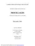
Figure 1: Lurette start-up.
Figure 1 shows what happens when Lurette starts up. Since the environment outputs serve as SUT
inputs, and SUT outputs serve as environment inputs (the first step excepted), in order to be able to start
such a looped design, one entity have to start first. The choice has been made that the environment will.
This means that a valid environment for Lurette is one that can generate values without any input at the
first instant.
The role of boot keyword of Figure 1 is precisely to indicate that the environment is indeed starting
first; once the environment received the boot signal, it (non-deterministically) produces an output vector
I, which will be used by the SUT. try I means that once one step is done in the SUT to compute its output
O, the previous state of the SUT is immediately restored. This allows several input vectors I to be tried
at each step, to perform a kind of thick test. In Figure 1, the different tries are distinguished thanks to the
index i. Hence, at the ith tries, the vectors Ii and Oi , respectively produced by the environment and the
SUT, are tried in the oracle.
Environment
Environment
try i oj
step j
Ii
step Ij
Test Manager
try Ii
Test Manager
SUT
SUT
Oi
step Ij Oj
ok
Oracle
try Ii Oi
Oracle
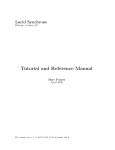
Figure 2: Lurette steps
Figure 3: Lurette tries.
Once a sufficient number of tries has been done (the thickness of the test is one of the Lurette parameters
users have control on, cf. Section 2.4), one index is chosen, say j, and the step corresponding to that index
is really1 done (Figure 2). Note that since the SUT and the oracle are deterministic machines, we just
need to give them the vector Ij and Oj once more. But this is not true for the environment, which is
non-deterministic; that is the reason why we give it the index j; of course, this means that the environment
interpreter needs to remember which index led to which internal state.
Then the process continues as in Figure 1; the only difference, as shown in Figure 3, is that the environment is fed with the SUT output vector Oj which was elected at the previous step (instead of boot i).
1 is
4/24
the sense that the previous state of machines is not restored this time.
Verimag Research Report no TR-2004-5
The Lurette V2 User Guide
2.4
Erwan Jahier
The XLurette Main window parameters
The most important test parameters can be set directly from the main Xlurette window. A snapshot of
the part of the main window that is dedicated to the setting of test parameters is shown in Figure 4 (For
a snapshot of the whole Main window, see e.g., Figure 7). In the following, we describe each of those
parameters in turn.
Figure 4: Part of the main window.
2.4.1
The SUT
The first line in Figure 4 lets one set the SUT. The first combo-box
name. One can either:
is to set the SUT file
1. type directly the name of the file;
2. Use the pull dow menu of the combo-box if the SUT file is in the lurette current directory;
3. Use the Browse button if the SUT is not in the current directory. Note that once one has selected
with the browse button a SUT in a directory that is not the same as the current one, the directory of
the selected file becomes the new current directory.
The second combo box is to set the SUT node.
The third combo box is to set the compiling mode. The various compiling modes are described below
(2.4.4).
2.4.2 The SUT Environment
The second line in Figure 4 lets one set the SUT environment file. Note that one can set several environment files (cf lucky manual [JR04]). In order to add a environment file to the list without discarding the
previously entered files, one has to type it manually (separating files with at least one blank), or use the
rigth-most browse button decorated with a “+” (which stands for “add”).
Note that the current directory does not change if an environment is selected in a directory that is not
the same as the current one.
2.4.3
The Oracle
The third line in Figure 4 lets one set the oracle. The only diffrences with the SUT is that setting an oracle
is optional, and that the current directory does not change if an oracle is selected in a directory that is not
the same as the current one.
2.4.4
The compiling modes
The SUT and the oracle can be either .saofdm, .lus or .c files. When the SUT is a .saofdm, there
is no ambiguity: the scade compiler should be used.
Verimag Research Report no TR-2004-5
5/24
Erwan Jahier
The Lurette V2 User Guide
However, for .lus files, lurette needs to know whether to use the Verimag or the Scade compiler. Furthermore, for .c files, lurette needs to know whether they follow the Verimag and the Scade conventions.
Users can specify the compiler mode using the combo boxes at the rigth-hand-side of the node names
(cf, Figure 4). They can choose between:
• verimag
• scade
• stdin/stdout
The first two items correspond to the verimag and the scade conventions that we have been just talking about. The third item correspond to an (experimental) completely different execution mode. In this
mode, users do not specify a SUT/oracle file and node name, but a system call that launches a program
that reads/writes its input/output on the standard input/output (stdin/stdout). The inputs must follow the
RIF convention (cf AppendixC), and the outputs will. For example, one can enter the string "ecexe
heater control.ec", because theecexe ec files interpreter reads and writes data on stdin/stdout
following the RIF conventions.
Watch out: in the verimag and scade modes, the link between the SUT, the environment and the
oracle is done via variable names, whereas in the stdin/stdout mode, it is done via the variable
positions of their declaration in the interface.
Note also that the test thickness parameters (cf 2.5.2) are (currently) ignored in the stdin/stdout
mode.
2.4.5
The Extra Environment variables window
One can launch the “Extra Environment Parameters” window by clicking on the button just below the
oracle line. A snapshot of this window is shown on Figure 5.
Figure 5: Setting extras environment variables window.
This window is meant to help users to add extras files or paths that are sometimes necessary for the
SUT or the oracle to compile. Thoses are used in the Makefile that builds the final test executable.
• EXTRA CFILES lets one add C files. For example, the scade compiler sometimes generates a file
named <sut> const.c that contains the definitions of the some of the SUT constants. C files
appearing in EXTRA CFILES are compiled and linked with the SUT by lurette.
• EXTRA LIBS lets one add libraries (<file>.a).
• EXTRA LIBDIRS lets one add paths to directories containing librairies.
• EXTRA INCLUDEDIRS lets one add paths to directories containing C header files.
For all those environment variables, one can put several items (separated by blanks), either manually
or using the browse button.
6/24
Verimag Research Report no TR-2004-5
The Lurette V2 User Guide
2.5
Erwan Jahier
The Test Parameters window
The “Test Parameters window” lets one set additional parameters; one can launch it by clicking on the
button. A snapshot of the Xlurette parameters window is shown on Figure 6. In the following, we describe
each of the available Lurette parameters – note that tool-tips are displayed if you leave your mouse pointer
long enough over each buttons or boxes in Xlurette GUI.
All those parameters can be saved to be used later in a next Xlurette session by clicking on button
(cf Figure 7). A file named .lurette-rc is then created (or updated) in the current directory.
2.5.1 The Test Length
The Test Length is the number of steps (or cycles) that should be generated.
2.5.2 The Test Thickness
We call the Test Thickness the number of test vectors that are generated by the test manager at each step.
Note that each vector is tried w.r.t. the oracle, but only one of them is elected to continue the testing process,
namely, to carry on with the next step.
The test thickness can be changed in several ways:
1. The Draw Formula Number (DF ). From any of the environment control points (cf [JR04]), several
formulas can be chosen to generate a SUT input vector. The DF indicates whether we try one or all
of them.
2. The Draw Number for Boolean variables (DB). For any formula that is used to generate a SUT input
vector, several Boolean values can generally be generated. The DB indicates how many of them we
do try.
3. The Draw Number Inside polyhedron (DI). For each Boolean solution of a formula corresponds a
(set of) polyhedron used to represent the solutions for the numeric variables. The DI indicates how
many points inside the polyhedron we try at each step.
4. The Draw Number at polyhedron Edges (DE). It plays a similar role as the DI, except that points
are drawn with the following heuristic: points at vertices, and then on the edges, and then inside
faces, and so for greater dimensions, are more likely to be drawn.
5. The Draw Number at polyhedron Vertices (DV ). Points are drawn among the polyhedron vertices.
One can either set the number of vertices to be drawn (Some button), or ask to draw all of them (All
button).
The Test Thickness (T T ) is therefore given by the formula:
T T = DF × DB × (1 + DI + DE + DV )
Note that if one of the Draw All Formula (via DF ) or Draw All Vertices (via DV ) modes is on, the
T T might change from one step to another.
2.5.3
The step mode
The step Mode is the policy that is used to draw solutions for numeric variables for performing the step. In
other words, DI, DE, and DV are used for Lurette tries, whereas the step mode is used for Lurette steps.
2.5.4
The random engine seed
The pseudo-random engine needs a seed to be initialised. One can either let Lurette draw a seed before
each run, or set its own one manually; this can be very useful to replay a run. Note also that, in the Random
mode, the integer next to the Manual button is set to automatically drawn seed. This means that if you
select that Manual button, the seed will be the one of the previous run.
Verimag Research Report no TR-2004-5
7/24
Erwan Jahier
The Lurette V2 User Guide
Figure 6: The Xlurette parameters window.
8/24
Verimag Research Report no TR-2004-5
The Lurette V2 User Guide
2.5.5
Erwan Jahier
Fairness versus efficiency
Emphasise the draw fairness over the computation time. This issue is detailed in the Section “The Lucky
Numeric solver” in the Lucky reference manual [JR04].
2.5.6
Running Lurette step by step
This mode can be set on and off via (so called) radio-buttons. When on, Lurette is run step by step, updating
a post-script visualisation of the Lucky automata (graph and current nodes) at each step. This requires dot
(a graph drawing tool [KN91]) and a post-script visualiser (gv) to be installed.
2.5.7
Call sim2chro when Lurette resumes
This mode can be set on and off via (so called) radio-buttons.
2.5.8
Put local variable in generated data file
This mode can be set on and off via (so called) radio-buttons.
2.5.9
Precision
The precision sets the number of digit after the dot used by the environment to perform numeric computations.
2.5.10
Base RIF file name
It is the first part of the RIF (see C) file name used to save the generated test data. The name of that
generated file is of the shape: <rif-file-name>-<int>.rif, where the integer is chosen in such a
way that the file does not previously exist in the current directory. If empty, a default string will be used: it
is made of the name of the sut, the name of the environment, and the test length.
Verimag Research Report no TR-2004-5
9/24
Erwan Jahier
3
The Lurette V2 User Guide
Supported Architectures and languages
Lurette has been tested with the following architectures:
• Ultra-sparc machine running Solaris 2.8;
• i686 running Linux;
• i686 running WindowsNt and Cygwin.
The System Under Test can either be:
• an academic Lustre program (.lus);
• a Scade2 program (.saofdm);
• a C file, provided that it follows the Verimag [Ray99] or the Scade code generators conventions.
Note that the SUT and the oracle can be in C (provided that they follow the poc or the scade conventions), but the SUT environment descriptions needs to be in Lutin, Lustre, or Lucky. Indeed, in the Lurette
testing process, the SUT and the oracle just need to be compiled and executed, whereas the environment
description needs to be parsed and interpreted.
2 only
10/24
tested with the 4.2 version
Verimag Research Report no TR-2004-5
The Lurette V2 User Guide
4
Erwan Jahier
Installation and configuration issues
The short story. Hopefully, you should only need to untar the package and run the INSTALL script.
> tar xvfz luretteV2-1.19.tgz
> cd luretteV2-1.19
> ./INSTALL
The xlurette tool is in the luretteV2-1.19/<arch>/bin/ directory, therefore you might
want to add it in your PATH env variable.
You can check that the installation works correctly by going to the test directory and launch a make
test command in your shell.
The long story. If you run into problems during the use of Xlurette, it might be useful for you to understand a little bit how things are organised to try to figure out how problems might be fixed.
The INSTALL script generates the luretteV2-1.19/<arch>/set env var file, that defines
various environment variables. Xlurette evaluates this file before running; therefore, it might be useful for
you to check the content of that file to see whether the information it contains seems correct. Be aware that
this file will be overridden if you run the INSTALL script again.
Another important file is luretteV2-1.19/<arch>/Makefile.lurette. It is the makefile
that is used to generate the final executable that Lurette runs. If Lurette runs fail, it might be useful for you
to check the content of that file, in particular in you use a scade version different from the 4.1.4, which is
the only one that has been tried.
Environment variables. Here is the list of all the environment variables that users can set to override
default values. The default values are set by the INSTALL script. You can consult them by looking at the
luretteV2-1.19/<arch>/set env var file.
• PS VIEWER: to set the tool used to visualize post-script files. Its default value is "gv".
• AWK: to override the awk that is used.
• DOT: to override the dot (a graph drawing tool) that is used. Its default value is "dot".
• SIM2CHRO: to override the rif viewer that is used.
• LUS2EC: to override the lustre to ec verimag compiler. Its default value is "lus2ec".
• EC2C: to override the ec to C verimag compiler. Its default value is "ec2c".
• SCADE2LUSTRE: to override the scade to lustre compiler. Its default value is "scade2lustre".
• SCADE CG: to override the scade code generator. Its default value is "scade cg".
• LUSTRE2C: to override the lustre to C scade compiler. Its default value is "lustre2c".
• SCADE COMPIL OPTION: to override additionnal options to be given to the scade compilers. Its
default value is " -noexp @ALL@ ".
Indeed, it is sometimes useful to override those default values to explicitely specify the full path of
tools that are used by Lurette.
Verimag Research Report no TR-2004-5
11/24
Erwan Jahier
5
The Lurette V2 User Guide
A small tutorial illustrating Lurette in action
In this Section, we assume that you have read the Lucky Reference Manual [JR04], since examples are
given in Lucky. All the files necessary to perform this tutorial are in the directory
lurette-V2-xxx/demo-xlurette/fault-tolerant-heater/ of the Lurette distribution.
5.1
A fault-tolerant heater controller in Lustre
We want to test a fault-tolerant heater controller which has three sensors (namely, three reals inputs) measuring the temperature in a room, and which returns a Boolean value saying to the heater whether it should
heat or not.
A Lustre implementation of such an heater is provided in Appendix A. We only provide here its
(informal) specification, which is enough from the Lurette black-box testing point of view.
The main task of that controller is to perform a vote to guess what the temperature is (Tguess).
Then, if that guessed temperature is smaller than a minimum value (TMIN), it heats; if it is bigger than a
maximum value (TMAX), it does not heat; otherwise, it keeps its previous state. The voter works as follows:
it compares the values of each sensors two by two, and consider sensors broken as soon as they differ too
much.
V12 = abs(T1-T2) < DELTA; -- true iff T1 and T2 are valid
V13 = abs(T1-T3) < DELTA; -- true iff T1 and T3 are valid
V23 = abs(T2-T3) < DELTA; -- true iff T2 and T3 are valid
Hence, there are four cases, depending on the values of V12, V13, and V23:
1. If the three comparisons are valid, it returns the median value of the three sensors;
2. If only one comparison is false, it considers it as a false alarm (e.g., because DELTA was too small)
and still returns the median value.
3. If two comparisons are false (say V12 and V13), it deduces the broken sensor (T1) and returns the
average of the other two (T2+T3/2.0);
4. If the three comparisons are false, it is difficult to know whether two or three sensors are broken, and
it safely decides not to heat in that case.
Technical remark: In order to test that program, there are two things we need to simulate: the real
temperature in the room, and the sensors that measure that temperature. A priori, the real temperature
could be a variable local to the SUT environment. But, in order to write oracles that have access to that
temperature, we need to add it in the SUT interface. That is the (technical) reason why the Lustre program
of Appendix A has an additional input T which it does not use.
5.2
A first test session using a fake environment
We launch the Xlurette tool in the directory containing the SUT: a snapshot of Xlurette is given in Figure 7. We first need to fill in the System Under Test fields – the file name and the node name – either manually or via so-called combo boxes
. In Figure 7, the SUT is a file named
heater control.lus, with the node heater control.
Then, we click on the run button
. We can observe on the Figure 8 that the following things (ought
to) happen:
• The SUT environment field has been filled in with a file named
heater control env.luc
• The test completed, and no property has been violated, which is not too surprising since we did not
provide any oracle yet.
12/24
Verimag Research Report no TR-2004-5
The Lurette V2 User Guide
Erwan Jahier
Figure 7: Lurette snapshot: selecting a SUT and a node with combo-boxes.
The content of that automatically generated environment file is given in Figure 9. It is a Lucky program
that has:
• one input variable (the output of the SUT): the
Boolean Heat on, which is true iff the heater
heats;
• and four output variables (the inputs of the
SUT): the true temperature in the room T, as
well as the temperature as it is measured by the
3 sensors: T1, T2, and T3.
inputs { Heat : bool
outputs { T:real;
T1:real; T2:real;
nodes { 0 : stable }
start node { 0 }
transitions {
0 -> 0
˜cond
0.0 < T and
and 0.0 < T1 and
and 0.0 < T2 and
and 0.0 < T3 and
}
T3:real }
T < 1.0
T1 < 1.0
T2 < 1.0
T3 < 1.0 }
This Lucky program is rather stupid; at each step,
Figure 9: The generated Lucky file.
it draws a real value between 0 and 1 for each of the
four outputs. The main advantage of this generated
program is that it provides a good start for writing a (more) sensible environments for the SUT, as the right
inputs and outputs have been declared. This can be convenient for programs that have a lot of inputs and
outputs.
, we obtain a window similar to the content of
Now, if we click on the data visualisation button
Figure 10.
5.3
A test session using hard-wearing sensors
In this Section, we enhance the generated environment and try to write a Lucky program that generates
more realistic input vectors for the System Under Test.
Verimag Research Report no TR-2004-5
13/24
Erwan Jahier
The Lurette V2 User Guide
Figure 8: Lurette snapshot: a fake environment has been generated.
The Lucky program sensors.luc provided in inputs { Heat:bool }
Figure 11 has the same interface as heater control env.luc,
outputs {
but in addition, it also have three local variables (eps1,
T:real ˜min 0.0 ˜max 50.0;
eps2, and eps3) that are uniformly drawn between −0.1
T1:real; T2:real; T3:real }
and 0.1. Those local variables are used to disturb the value of locals {
eps1:real ˜min -0.1 ˜max 0.1;
the temperature T and simulate the noise a sensor may have
eps2:real
˜min -0.1 ˜max 0.1;
(T1 = T + eps1).
Then, we need to simulate T. To do that, we use two transitions: the first transition (0 -> 1) initialises the temperature to 7. The second transition 1 -> 1, from step 2 until
the end, updates T as follows: if Heat on is true, then T is
incremented of 0.2; otherwise, it is decremented of 0.2.
This model is quite simple, but it will be refined further
latter.
eps3:real ˜min -0.1 ˜max 0.1; }
nodes { 0 : stable }
start node { 0 }
transitions {
-- initialisation
0 -> 1 ˜cond T = 7.0
and T1 = T + eps1
and T2 = T + eps2
and T3 = T + eps3;
-- Running loop
1 -> 1 ˜cond T = pre T +
(if Heat then 0.2 else -0.2)
and T1 = T + eps1
and T2 = T + eps2
and T3 = T + eps3 }
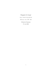
An Xlurette run using the Lucky program of Figure 11
produced the timing diagram of Figure 12. There, we can
convince ourselves that everything seems to work correctly;
the temperature increases and Heat on is true until TMAX is
reached. Then, at step 11, Heat on becomes false and the Figure 11: sensors.luc: a Lucky protemperature decreases until TMIN is reached, and so on.
gram simulating hard-wearing sensors.
14/24
Verimag Research Report no TR-2004-5
The Lurette V2 User Guide
Erwan Jahier
1
T
T1
T2
T3
Heat_on
0.9
0.8
0.7
0.6
0.5
0.4
0.3
0.2
0.1
0
0
5
10
15
20
25
30
35
40
45
50
steps
Figure 10: The timing diagram of an execution generated with the automatically generated environment.
10
T
T1
T2
T3
sensors__eps1
sensors__eps2
sensors__eps3
Heat_on
9
8
7
6
5
4
3
2
1
0
-1
0
5
10
15
20
25
30
35
40
45
50
steps
Figure 12: The timing diagram of an execution generated with the hard-wearing sensors.
5.4
Specifying an oracle
Now that sensible values have been generated, it is time to think about how to decide automatically if the
test succeeded. The property that we propose to check is described by the Lustre observer of Figure 13
which states that the temperature should never be bigger than TMAX+1 even if all sensors are broken. To
take that oracle into account in Xlurette, we fill the oracle fields in the same manner as for the SUT, using
combo-boxes, as Figure 14 illustrates.
If we run again our program, we observe that indeed this oracle is never violated.
Note that if you do not specify any oracle, a fake one, named always true.lus that always returns
true is generated. In the same manner as for the generated environment, this oracle can be used as a
template to write less trivial properties.
5.5
A test session using wearing sensors
The Lucky program of Figure 15 models more realistic sensors that wears out. The input, output, as well
as the epsi local variables are the same ones as in the sensors.luc Lucky program of Figure 11 – we
have omitted them in the Figure for the sake of conciseness of the code.
There are two additional local variables: cpt, that is incremented at each cycle, and inv, an invariant
that states how the temperature T is simulated (basically as before) and how to update cpt at each cycle.
Verimag Research Report no TR-2004-5
15/24
Erwan Jahier
The Lurette V2 User Guide
node not_a_sauna(T, T1, T2, T3 : real; Heat_on: bool)
returns (ok:bool);
let
ok = true -> pre T < TMAX + 1.0;
tel
Figure 13: The oracle of the test session: make sure that temperature never becomes infernal.
Figure 14: Lurette snapshot: selecting an oracle.
The two transitions s1 -> t1, t1 -> s1 describes exactly the same kind of behaviour as the
transition 1 -> 1 in Figure 11: T1, T2, and T3 are computed as disturbed version of T. Transitions t2
-> s2, s2 -> t2 simulates the case where one sensor is broken: T1 keeps its previous value (pre
T1) whatever the temperature is. Transitions t3 -> s3, s3 -> t3 and transitions t4 -> s4, s4
-> t4 respectively simulate cases where respectively two and three sensors are broken.
Let us run through the execution of that automaton into more detail. The initial node is the one labelled
by t0. The output values for the first cycle are given by the equation that labels the transition t1 -> s1,
which states that outputs T, T1, T2, and T3, are set to 7.0, and the local counter cpt is set to 0.
The values for the second cycle are computed via one of the two transitions outgoing from node s1:
s1 -> t1, which is labelled by 10000, and s1 -> t2 which is labelled by pre cpt. The meaning
10000
of those weights is the following: use the first transition with a probability of 10000+pre
cpt and the second
pre cpt
one with a probability of 10000+pre cpt . At second cycle, since pre cpt is bound to 0, the only possible
transition is the second one, which leads to a correct behaviour of all sensors.
At the third cycle, the situation is roughly the same, except that the transition s1 -> t2 is now
1
possible, with a probability of 10001
. If this transition is taken, we enter in a mode where one sensor is
broken. Note that as time flies, the probability to go to the node t2 increases; this somehow models that the
probability of failure increases with time.
16/24
Verimag Research Report no TR-2004-5
The Lurette V2 User Guide
Erwan Jahier
locals { cpt : int ;
eps : float ˜min 0.0 ˜max 0.2;
inv : bool ˜alias -- invariant
(cpt = pre cpt + 1) and 0.0 < T and T < 50.0 and
T = pre T + (if Heat then eps else -eps);
new_T1 : bool ˜alias T1 = T + eps1 ;
new_T2 : bool ˜alias T2 = T + eps2 ;
new_T3 : bool ˜alias T3 = T + eps3 }
nodes { t0, t1, t2, t3, t4 : transient; s1, s2, s3, s4 : stable }
start node { t0 }
transitions {
-- initialisation
t0 -> s1 ˜cond T=7.0 and T1=T and T2=T and T3=T and cpt=0;
-- No sensor is broken
t1 -> s1 ˜cond inv and new_T1 and new_T2 and new_T3 ;
s1 -> t1 ˜weight 1000 ;
s1 -> t2 ˜weight pre cpt;
-- One sensor is broken
t2 -> s2 ˜cond inv and new_T1 and new_T2 and T3 = pre T3;
s2 -> t2 ˜weight 1000 ;
s2 -> t3 ˜weight pre cpt;
-- Two sensors are broken
t3 -> s3 ˜cond inv and new_T1 and T2 = pre T2 and T3 = pre T3;
s3 -> t3 ˜weight 1000 ;
s3 -> t4 ˜weight pre cpt;
-- Three sensors are broken
t4 -> s4 ˜cond inv and T1 = pre T1 and T2 = pre T2 and T3 = pre T3;
-- starts again from the beginning
s4 -> t0; }
Figure 15: A Lucky program simulating wearing sensors.
The behaviour is similar at nodes s2 and s3. When all sensors are broken, we go back to the initial
state and continue the test.
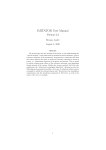
If we run the test with wearing sensors.luc often enough – or with a test length that is long
enough –, we can exhibit sequences that violate the oracle. An example of such a sequence is shown in the
timing diagram of Figure 16.
Indeed, since the way we modelled sensor breakdowns was by making them keep their previous value,
this means that if ever two sensors broke down with similar values, the voter will not be able to realise that
they are broken, and hence the controller keeps on heating forever.
One possibility to correct that bug would be to check that sensor values do change during a given
number of cycles, and to consider them – at least temporarily – invalid otherwise.
Verimag Research Report no TR-2004-5
17/24
Erwan Jahier
The Lurette V2 User Guide
12
T
T1
T2
T3
Heat_on
10
8
6
4
2
0
0
50
100
150
200
250
300
350
400
450
500
steps
Figure 16: The timing diagram of an execution generated with the wearing sensors exhibiting the test
failure.
References
[Jea02]
B. Jeannet.
The Polka Convex Polyhedra library Edition 2.0,
www.irisa.fr/prive/bjeannet/newpolka.html. B.3
[JR04]
Erwan Jahier and Pascal Raymond. The Lucky Language Reference Manual. Technical Report
TR-2004-6, Verimag, 2004. www-verimag.imag.fr/∼synchron/tools.html. 1, 2.1, 2.4.2, 1,
2.5.5, 5
[KN91]
E. Koutsofios and S. North. Drawing graphs with dot. TR 910904-59113-08TM, AT&T Bell
Laboratories, 1991. 2.5.6
[Ray99]
P. Raymond. POC, Jan 1999. www-verimag.imag.fr/∼synchron/tools.html. 2
[Rou04]
Y. Roux.
The LuTin Reference Language
verimag.imag.fr/∼synchron/tools.html. 2.1
[RR02]
P. Raymond and Y. Roux. Describing non-deterministic reactive systems by means of regular
expressions. In First Workshop on Synchronous Languages, Applications and Programming,
SLAP’02, Grenoble, April 2002. 2.1
Manual,
Jan
2004.
May 2002.
www-
[RWNH98] P. Raymond, D. Weber, X. Nicollin, and N. Halbwachs. Automatic testing of reactive systems.
In 19th IEEE Real-Time Systems Symposium, Madrid, Spain, December 1998. 1, 1
[Som98]
18/24
F. Somenzi. CUDD: CU Decision Diagram Package Release 2.3.0, 1998. B.3
Verimag Research Report no TR-2004-5
The Lurette V2 User Guide
Erwan Jahier
Figure 17: Lurette snapshot: the oracle has been violated.
A
The fault-tolerant heater controller
const FAILURE = - 999.0; -- temperature given when all sensors are broken
const TMIN = 6.0;
const TMAX = 9.0;
const DELTA = 0.5;
----------------------------------------------------------------------node heater_control(T, T1, T2, T3 : real) returns (Heat:bool);
var
V12, V13, V23 : bool;
Tguess : real;
let
V12 = abs(T1-T2) < DELTA; -- Are T1 and T2 valid?
V13 = abs(T1-T3) < DELTA; -- Are T1 and T3 valid?
V23 = abs(T2-T3) < DELTA; -- Are T2 and T3 valid?
Tguess =
if noneoftree(V12, V13, V23) then FAILURE else
if oneoftree(V12, V13, V23) then Median(T1, T2, T3) else
if alloftree(V12, V13, V23) then Median(T1, T2, T3) else
-- 2 among V1, V2, V3 are false, one one is true
if V12 then Average(T1, T2) else
if V13 then Average(T1, T3) else
-- V23 is necessarily true, hence T1 is wrong
Average(T2, T3) ;
Heat = true ->
if Tguess = FAILURE then false else
Verimag Research Report no TR-2004-5
19/24
Erwan Jahier
if Tguess < TMIN
if Tguess > TMAX
The Lurette V2 User Guide
then true else
then false else pre Heat;
tel
----------------------------------------------------------------------node Average(a, b: real) returns (z : real);
let
z = (a+b)/2.0 ;
tel
node Median(a, b, c : real) returns (z : real);
let
z = a + b + c - min2 (a, min2(b,c)) - max2 (a, max2(b,c)) ;
tel
node noneoftree (f1, f2, f3 : bool) returns (r : bool)
let
r = not f1 and not f2 and not f3 ;
tel
node alloftree (f1, f2, f3 : bool) returns (r : bool)
let
r = f1 and f2 and f3 ;
tel
node oneoftree (f1, f2, f3 : bool) returns (r : bool)
let
r = f1 and not f2 and not f3 or
f2 and not f1 and not f3 or
f3 and not f1 and not f2 ;
tel
------------------------------------------------------------------------ The oracle
node not_a_sauna(T, T1, T2, T3 : real; Heat: bool) returns (ok:bool);
let
ok = true -> pre T < TMAX + 1.0;
tel
20/24
Verimag Research Report no TR-2004-5
The Lurette V2 User Guide
B
Erwan Jahier
Lurette Architecture – Components Description
In this Appendix, we present the different tools, resource files and libraries that are involved in the production of the final executable that performs the testing. We also describe how the SUT, the test Oracle, and
the SUT environment are be connected one to each other.
B.1 Interfacing Lurette with the SUT
In order to run the test, as far as the SUT is concerned, Lurette needs to be able to:
1. read/write its input/output (read o and write i);
2. perform a try, namely, to have a mean to save and restore the SUT state (try).
3. perform a step (step);
The two languages we support are the academic Lustre (Verimag), and Scade (Esterel-Technologies).
Both compiles into C code, but with distinct interfaces in the way the 4 interfaces functions (read o,
write i, step and try) are to be performed. Moreover, Lurette should be able to be used to test any
reactive system code, for which compilers would certainly have (similar but) different interfaces. For that
reason, the calls to the SUT interface functions should not be hard-coded: Lurette calls an abstract interface,
that is implemented for each different SUT code compiler (namely, for the time being, the academic Lustre
compiler and the Scade one).
sut.lus /
lus2c /
scade2c
cc
sut.o
sut.c
sut.saofd
gen_stubs_lustre /
gen_stubs_scade
cc
sut_stubs.c
sut_stubs.o
Figure 18: Object Code Generation for the SUT.
The implementation of this abstract interface for the Lustre and the Scade compilers is materialised in
Figure 18 by the gen stubs lustre and gen stubs scade tools. The generated C code is parsed
in order to retrieve the input and output variable names and types. The generated file sut_stubs.c implements the abstract interface that provides to LURETTE EXE the interface functions read o, write i,
step and try.
Figure 18 also makes explicit the usual Lustre / Scade code compilation process into c (lustre2c /
Scade2c), and the object code generation with a C compiler (cc).
B.2 Interfacing Lurette with the Oracle
In the current scheme, the oracle is written in the same language as the SUT (Lustre or Scade). Therefore,
the interfacing work is exactly the same as for the SUT.
B.3 Interfacing Lurette with the Environment simulator
The main part of the Lurette implementation effort lies in the Lucky programs simulation. At this level
of the description, we only focus on the description of the connection between components; we therefore
suppose that we have read o, write i, step and try functions for the environment too.
Verimag Research Report no TR-2004-5
21/24
Erwan Jahier
The Lurette V2 User Guide
sut.o, sut_stubs.o
links
reads
LURETTE_EXE
oracle.o, oracle_stubs.o
Test Parameters
links
links
polyhedron.a
links
reads
lucky_lib.a
bdd.a
env.luc
links
Figure 19: Lurette Components diagram.
An outline of the different components involved in the final executable file LURETTE EXE is provided
in Figure 19. The object code files sut.o and sut stubs.o as well as oracle.o and oracle stubs.o
are linked with the Lucky (env.luc) file interpreter library lucky lib.a.
Note the lucky lib.a uses two external libraries: a Binary Decision Diagram library [Som98]
(bdd.a) to deals with Boolean variables; and a convex Polyhedron Library (polyhedron.a) to deal
with numeric variables [Jea02].
22/24
Verimag Research Report no TR-2004-5
The Lurette V2 User Guide
C
Erwan Jahier
The RIF conventions
RIF stands for Reactive Input Format. It is the format used by the synchronous Verimag tools for writing
and reading sequences of input and output data vectors. We recall in this section what this format looks
like.
Data. A RIF file is essentially a sequence of data values separated by spaces, newlines, horizontal tabulations, carriage returns, line feed and form feeds. A data value can be either an integer, a floating-point or
a Boolean (t, T, or 1 stands for true ; f, F or 0 stands for false).
Comments. Single line comments are introduced by the two character # and terminated by a new line.
Multi-line comments are introduced by the two characters @#, and terminated by the two characters #@.
Pragmas. Pragmas are special kinds of comments, that migth (or not) be taken into account by tools that
reads RIF data. One-line pragmas have the form #pragma ident ... , and multi-line pragmas the form
@#pragma ident ... #@. The most common pragmas used by verimag tools are (using BNF notation):
• @#inputs (<var name> : <var type>)+ #@, to declare the list of input variable names and types;
• @#outputs (<var name> : <var type>)+ #@, to declare the list of output variable names and
types;
• @#locals (<var name> : <var type>)+ #@, to declare the list of local variable names and types;
• #outs, to indicate that the following data correspond to output variables;
• #locs to indicate that the following data correspond to local variables;
• #step int, to indicate that a new step is starting, and that the following data correspond to input
variables.
Note that those pragmas are necessary for RIF file viewers such as sim2chro and gnuplot-rif to
work properly.
A RIF file example is provided in Figure 20; it corresponds to the timing diagram of Figure 16.
Verimag Research Report no TR-2004-5
23/24
Erwan Jahier
The Lurette V2 User Guide
# seed = 97040004
#program "lurette chronogram (wearing-sensors.luc) "
#@inputs
"T":real
"T1":real
"T2":real
"T3":real
@#
#@locals
"wearing-sensors__cpt":int
"wearing-sensors__eps":real
"wearing-sensors__eps1":real
"wearing-sensors__eps2":real
"wearing-sensors__eps3":real
@#
#@outputs
"Heat_on":bool
@#
#step 1
7.00 7.00 7.00 7.00 #outs T
#locs 0 0.08 -0.05 -0.05 0.10
#step 2
7.13 7.20 7.16 7.18 #outs T
#locs 1 0.13 0.07 0.03 0.05
#step 3
7.27 7.37 7.27 7.18 #outs T
#locs 2 0.14 0.10 -0.00 -0.09
#step 4
7.45 7.47 7.38 7.36 #outs T
#locs 3 0.18 0.02 -0.07 -0.09
#step 5
7.59 7.68 7.61 7.56 #outs T
#locs 4 0.14 0.09 0.02 -0.03
#step 6
7.65 7.58 7.64 7.55 #outs T
#locs 5 0.06 -0.06 -0.01 -0.09
#step 7
7.84 7.91 7.94 7.90 #outs T
#locs 6 0.20 0.07 0.10 0.06
#step 8
8.00 8.07 8.00 8.09 #outs T
#locs 7 0.15 0.07 0.00 0.09
#step 9
8.12 8.09 8.17 8.16 #outs T
#locs 8 0.13 -0.03 0.05 0.04
#step 10
8.26 8.29 8.30 8.20 #outs T
Figure 20: A RIF file example.
24/24
Verimag Research Report no TR-2004-5