1
Installation and User Guide
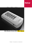
iDIM Remote Control (304)
Product description
The iDim Remote Control (304) can be used with the iDim Sense Standalone to modify the preset light levels and recall/
store scenes, as well as to activate special functions (100-h Burn-In, PIR Walk test and Mode Identification).
Combined with iDim Studio, the 304 iDim Remote can provide further advanced configuration. Please see document iDim
Studio Help or iDim User Manual (D004735) for further information.
Note: Throughout this document, ‘Controller’ refers to iDim Sense and/or DIGIDIM Button Panels.
A.
LED indicator (Flashes when comms
transfer is in progress and when buttons
pressed)
D.
OK key
I.
Mode selection button
E.
1 – 4 Scene Recall / Configuration
J.
Battery cover
F.
Function key (Fn)
K.
USB connection (Mini B)
B.
Up modifier
G.
Lights off ( )
C.
Down modifier
H.
Transmitter
Helvar | Data is subject to change without notice.
www.helvar.com
i
Contents
SectionPage
ii
Product description
i
Add / Remove Batteries
1
Assemble iDim Remote Cradle for Desktop Use
1
Setup iDim Remote Cradle for Wall Attachment
1
Attach iDim Remote to Cradle
1
Connecting the iDim Remote to your PC
2
Switching Lights On / Recall Scenes using iDim Remote
2
Modify Light Levels using iDim Remote
2
Modify Light Levels using iDim Remote
3
Stores Scenes using iDim Remote
4
Special Functions using iDim Remote
4
Special Functions using iDim Remote (cont.)
5
Special Functions using iDim Remote
6
iDim Sense LED Flash Feedback
7
Technical Data
8
Helvar | Data is subject to change without notice.
www.helvar.com
Add / Remove Batteries
To add or remove batteries:
1.
Unclip the battery cover on the reverse of the
remote.
2.
Add batteries, observing correct polarity and replace
cover.
1.
Note: Batteries not required if running iDim Remote
Control through a PC via USB cable.
Assemble iDim Remote Cradle for Desktop Use
To assemble the iDim Remote Cradle for desktop use:
1.
Attach rubber feet A to base B.
2.
Insert base B into recess C on the reverse of the
cradle until it clicks.
To disassemble the iDim Remote Cradle (not shown):
Insert flat head screwdriver into recess C and gently
lever base A away from the cradle to avoid the unit
being damaged.
B
C
Helvar
Helvar
A
Setup iDim Remote Cradle for Wall Attachment
To mount the iDim Remote Cradle to a wall:
1.
Drill and insert screw to chosen mounting location. Leave approx 1 mm between screw head and wall to
allow cradle to sit comfortably on screw.
2.
Carefully slide the cradle onto the screw adjusting
screw tightness as required.
3.
With cradle still wall mounted, mark hole A on the
wall.
4.
Remove cradle, drill second hole and apply wall
plug.
5.
Slide cradle back on to wall and insert bottom screw.
Tighten screw as needed.
A
Attach iDim Remote to Cradle
To attach the iDim Remote to the remote cradle:
1.
Place iDim Remote onto cradle mounting point.
2.
Push iDim Remote downwards until it clicks, holding
the unit in place.
Note: Remove the iDim remote by following the above
procedure in reverse.
1
Helvar 304 iDIM Remote Control: Installation and User Guide
Helvar
Doc. 7860263, issue 5,
2014-08-28
Connecting the iDim Remote to your PC
Note 1:
The iDim Remote only needs to be connected to
a PC if you want to set advanced configuration
settings via your PC.
The remote will work without iDim Studio.
Note 2:
To download iDim Studio please visit
www.helvar.com
To connect the iDim Remote to your PC:
1.
Attach Mini USB connector to iDim remote.
2.
Connect the opposite end of the USB cable to
the USB port of the PC. The new device will be
automatically recognised.
3.
Run iDim Studio (if installed)
2.
1.
Do NOT disconnect iDim Remote
when the LED is flashing red.
While using iDim Studio software, the iDim Remote LED
flashes red when device communication is in progress.
Do not disconnect the iDim Remote from PC during this time.
Switching Lights On / Recall Scenes using iDim Remote
To switch lights on / recall a scene using the iDim remote:
1.
2.
Point the remote at a controller. Point the remote at
a controller
5
1
Press scene key 1, 2, 3 or 4 to recall the required scene.
2
6
3
7
4
O
To switch lights off:
1.
Point the remote at a controller.
2.
Press
1
key on remote control to switch the lights off.
When lights are switched off via a remote, switch or panel;
a 90‑second exit delay will start. During this time any PIR
movement will extend the delay.
3
2
4
0%
1
2
5
6
3
7
4
O
The exit delay will be cancelled when a new scene is
manually selected.
Modify Light Levels using iDim Remote
DALI 1 and DALI 2 scenes operate as a combination of Constant Light (CL), Fixed Light (FL) and Offset dependent on which
of the 6 iDim modes that an iDim Sense is in and the scene selected. It is possible to modify the DALI 1 and DALI 2 levels
using the iDim Remote. The adjusted levels will only be temporary unless they are stored into the already selected scene.
For example:
• If DALI 1 is a Constant Light Scene then modifying the levels will cause the Constant Light target level to be modified.
• If DALI 1 is a Fixed Light scene then the Fixed Light level will be modified.
• If operating in Constant Light + Offset mode, the DALI 2 level will also be affected if DALI1 is modified.
Please refer to table 1 overleaf for default DALI 1 and 2 scene setup for each iDim mode.
Other advanced configuration such as configuring the bright out level is only possible using the iDim Studio software.
2
Helvar 304 iDIM Remote Control: Installation and User Guide
Doc. 7860263, issue 5,
2014-08-28
Modify Light Levels using iDim Remote
When modifying the constant light target levels for your system, please ensure that the process is done in a darkened room
or during dusk, as excessive natural light may result in levels being recorded by the sensor that are not actually achievable.
Table 1: Default DALI 1 and DALI 2 Constant Light, Fixed Light and Offset configuration for the six default iDim modes.
In this table, ‘iDim Controller’ refers to iDim Remote, Switches and Panels unless specified.
1
CLASSROOM
iDim Controller
Scene 1
iDim Controller
Scene 2
iDim Controller
Scene 3
iDim Controller
Scene 4
2
3
4
5
6
SINGLE
OPEN-PLAN
CORRIDOR
CORRIDOR
MEETING
OFFICE
OFFICE
LINK
HOLD
ROOM
CL
CL
Link to
See notes
corridor1
below2
CL
-
DALI 1
CL
CL
CL
FL (100 %)
DALI 2
Offset
Offset
Offset
FL (100 %)
DALI 1
CL
CL
CL
FL (70 %)
DALI 2
Offset
Offset
Offset
FL (70 %)
DALI 1
FL (100 %)
FL (100 %)
FL (100 %)
FL (40 %)
DALI 2
FL (100 %)
FL (100 %)
FL (100 %)
FL (40 %)
DALI 1
FL (40 %)
FL (40 %)
FL (40 %)
FL (10 %)
DALI 2
FL (40 %)
FL (400 %)
FL (40 %)
FL (10 %)
Link to
FL (100 %)
corridor1
FL (100 %)
-
Link to
FL (0 %)
corridor1
FL (40 %)
FL (40 %)
Link to
FL (20 %)
corridor1
Note 1:
In Corridor Hold (iDim Mode 5), DALI 2 is only used to connect an offi ce to the corridor.
Note 2:
In Meeting Room (iDim Mode 6), iDim Solo SW1 input operates DALI 1 CL / Off and SW2 input operates DALI 2
FL (100 %) / Off; as SW1 is located at the entrance of a room, switching off SW1 will cause both DALI 1 and DALI
2 circuits to go off.
DALI 1
To modify light levels using the iDim remote:
1.
Point the remote at a controller.
2.
Select the scene that you want to modify.
3.
Press DALI 1 modifier key up to raise DALI 1 light level.
4.
Press DALI 1 modifier key down to lower DALI 1 light level.
5.
Press DALI 2 modifier key up to raise DALI 2 light level.
6.
Press DALI 2 modifier key down to lower DALI 2 light level.
1
2
7
4
O
Note 3:
3
Ch
Ch
1%
100 %
100 %
1%
DALI 2
2
Note 2: Scene 1 is the default ‘on’ scene selected by PIR
movement and Solo SW1 and SW2.
6
3
1
Note 1: If you intend to store the modified levels, ensure that the
required scene number is selected before modifying.
5
5
6
3
7
4
O
Ch
Ch
1%
100 %
100 %
1%
When operating in Constant light + Offset mode, the DALI
1 and DALI 2 levels will both adjust together.
Helvar 304 iDIM Remote Control: Installation and User Guide
Doc. 7860263, issue 5,
2014-08-28
Stores Scenes using iDim Remote
To store a modified scene using the iDim remote:
1.
Point the remote at a controller.
2.
Hold scene key 1, 2, 3 or 4 for 10 seconds to store
scene.
iDim Sense LEDs will flash green if scene successfully stored.
The iDim mode will then flash the iDim mode number red /
green to signify that the iDim Sense is in User Defined mode.
Note: Mode flash will only occur when storing scenes for
the first time. Further scenes stores will only activate
green scene store LED.
To exit User Defined mode and reset the iDim Sense to default
mode settings, the iDim Remote Control must be in ‘special
IDim Sense LED flash feedback
1
1
2
5
6
3
7
4
O
2
10 s
3
4
625 ms
250
ms
125
ms
250
ms
125
ms
Example for mode 2
(Single Office Mode)
function mode’. Please see chapter below for more
information.
Special Functions using iDim Remote
It is possible to make the iDim Remote perform advanced tasks to assist commissioning and system testing. The iDim
Remote uses a ‘special function mode’ where these advanced tasks can be configured. This mode must be activated before
a special function or test is run. This avoids accidental configuration changes or tests being run which could cause the
light levels or scenes to be altered unintentionally.
Please see below for activating and deactivating special function mode. See pages 7 - 8 for the types of special functions
possible.
To activate special function mode:
1.
Remove the battery cover from the remote control.
2.
Using a pen (or other long blunt object), press mode
selector button on the reverse of the iDim Remote
for 3 seconds.
3 seconds
Special function mode is now active.
3.
Check that the iDim Remote is in special function
mode by recalling a scene. The iDim Remote LED
will flash orange when a function (i.e. Scene recall)
is performed.
4.
Run the special functions that you require. (See
pages 7 and 8 for special functions)
Note 1: All standard operation settings, such as scene recall,
modify and store scene, are still possible when the
iDim Remote is in special function mode.
When a remote key is pressed
during standard operation,
iDim Remote LED flashes
green.
Note 2: Once special function mode is activated, it will
remain so until it is manually deactivated.
To deactivate special function mode:
4
1.
Hold the mode selector button for 1 second to return
to standard operation. Special function mode is now
deactivated.
2.
Check that the iDim Remote is in standard operating
mode by recalling a scene on the remote. The iDim
Remote LED should flash green when scene recall
is called.
Helvar 304 iDIM Remote Control: Installation and User Guide
When a remote key is pressed
in special function mode, iDim
Remote LED flashes orange.
When the iDim Remote is
communicating with a PC,
the iDim Remote LED flashes
red. Do NOT disconnect
during this time.
Doc. 7860263, issue 5,
2014-08-28
Special Functions using iDim Remote (cont.)
Start/Stop 100‑hour Burn-In Mode
IDim Sense LED flash feedback
To start or stop Burn-In mode:
1.
Ensure the iDim Remote is in special function mode.
2.
Point the remote at a controller.
3.
Press Fn key and scene 1 at same time.
250
ms
Lights will blink 4 times and then go to 100 %. The
100‑hour Burn-In counter will begin.
4.
250
ms
30 s
...
To stop Burn-In mode, press Fn key and scene 1.
Note: Restarting a Burn-In test following a stop will cause
the 100‑hour Burn-In time to be reset. Use Resume
Burn-In Mode to continue a stopped Burn-In test.
Resume Burn-In Mode
To resume a stopped Burn-In mode:
1.
Ensure the iDim Remote is in special function mode.
2.
Point the remote at a controller.
3.
Press Fn key and scene 2 at the same time.
IDim Sense LED flash feedback
5
1
6
2
3
7
4
O
2
+ Fn
...
Lights blink 4 times and go to 100 % if Burn-In counter
is not at zero.
250
ms
30 s 250
ms
...
Note: If a Power Off / On cycle occurs, the Burn-In time will
be reset to 100 hours.
Mode Identification
IDim Sense LED flash feedback
To establish which iDim mode is selected:
1.
Ensure the iDim Remote is in special function mode.
2.
Point the remote at a controller.
3.
Press Fn key and scene 3 at the same time.
1
5
2
6
3
7
4
O
3
+ Fn
If Mode 1 has not been
modified.
250
ms
If Mode 1 is in
250
125
ms
ms
iDim Sense LEDs will flash the current mode.
User Defined mode
Note: Number and type of flashes depends on mode selected
and if the iDim Sense is in User Defined mode.
Start/Stop PIR Walk Test
IDim Sense LED flash feedback
To start/stop PIR Walk test:
1
1.
Ensure the iDim Remote is in special function mode.
2
6
3
7
4
O
2.
Point the remote at a controller.
3.
Press Fn key and scene 4 at the same time.
5
4
+ Fn
iDim Sense will flash then wait for 10 s before looking
for movement. When movement is detected: lights will
go on for 5 s; to transition level for 5 s, off for 5 s and
then return to the currently selected mode.
1 sec
Reset Mode
To reset a controller to factory default settings:
1.
Ensure the iDim Remote is in special function mode.
2.
Point the remote at a controller.
3.
Press and hold key 3 and 4 at same time for 10 s.
Note: Lights will behave in the same manner as when
powered up for the first time in the mode currently
selected.
5
Helvar 304 iDIM Remote Control: Installation and User Guide
1
6
7
4
O
...
Note:
5
2
3
1 sec
3
+ 4
The active mode flashes
e.g.
2 flashes when mode 2
selected.
10 s
250
ms
250
ms
Doc. 7860263, issue 5,
2014-08-28
Special Functions using iDim Remote
Enable IR Receiver
To enable the Infrared receiver of a controller:
1.
Ensure the iDim Remote is in special function mode.
2.
Point the remote at a controller.
3.
Press and hold DALI 1 modifier up and Fn key at the
same time for 10 seconds.
IDim Sense LED flash feedback
1
5
2
6
3
7
4
O
Ch
IDim Sense LED flash feedback
To disable the Infrared receiver of a controller:
Ensure the iDim Remote is in special function mode.
2.
Point the remote at a controller.
3.
Press and hold DALI 1 modifier down and Fn key at
the same time for 10 seconds.
125
ms
10 s
Disable IR Receiver
1.
+ Fn
1
5
2
6
3
7
4
O
Ch
+ Fn
125
ms
10 s
Lock iDim Sense Mode Selector Ring
IDim Sense LED flash feedback
To lock the mode selector ring of an iDim Sense:
1
1.
Ensure the iDim Remote is in special function mode.
3
7
4
O
2.
Point the remote at the iDim Sense you wish to lock.
3.
Press and hold DALI 2 modifier up and Fn key at the
same time for 10 seconds.
2
5
6
Ch
125
ms
+ Fn
10 s
Note: When locked, the iDim Sense mode selector ring
can still be manually turned. However, the modes will
be ignored unless the mode selector ring is unlocked.
Unlock iDim Sense Mode Selector Ring
To unlock the mode selector ring of an iDim Sense:
1.
Ensure the iDim Remote is in special function mode.
2.
Point the remote at the iDim Sense you wish to unlock.
3.
Press and hold DALI 2 modifier down and Fn key at the
same time for 10 seconds.
IDim Sense LED flash feedback
1
2
5
6
3
7
4
O
Ch
125
ms
+ Fn
10 s
Note: iDim Sense will remain in the selected mode (and in
user defined mode where applicable) until the mode
selector ring is turned again.
Advanced Configuration with iDim Studio Software
Note: All standard operation settings such as scene recall, modify and store scene are still possible when the iDim Remote
is in special function mode.
Transfer settings to iDim Sense using iDimRemote
To transfer settings to iDim Sense using iDim Remote:
6
1.
Ensure the iDim Remote is in special function mode.
2.
Point the remote at a controller.
3.
Press OK and Fn key at same time.
Helvar 304 iDIM Remote Control: Installation and User Guide
625 ms
125
ms
125
ms
125
ms
125
ms
Doc. 7860263, issue 5,
2014-08-28
iDim Sense LED Flash Feedback
Two LEDs, red and green, in the iDim Sense flash to provide visual feedback, for various states and operations.
Function
LED flash feedback
Mode unmodified
User defined mode selected*
(default mode)
Mode 1 Selected
(Classroom mode)
250
ms
Mode 2 Selected
250
ms
250
ms
250
ms
250
ms
250
ms
250
ms
250
ms
250
ms
250
ms
250
ms
250
ms
250
ms
250
ms
250
ms
250
ms
250
ms
250
ms
250
ms
250
ms
(Single Office mode)
Mode 3 Selected
(Open Plan mode)
Mode 4 Selected
(Corridor Link mode)
Mode 5 Selected
(Corridor Hold mode)
Mode 6 Selected
(Meeting Room mode)
PIR Walk Test Mode
1 sec
Sequence repeats until walk test is complete.
100‑hour Burn-In Mode
Sequence repeats until burn-in is complete.
DALI Errors
Sequence repeats until error clears.
Change from unoccupied to occupied
Typically follows a PIR detection.
Data received from IR Remote
Enabling / Disabling of IR Receiver
250
250
msms
250
ms
250
ms
250
ms
250
250
ms
ms
250
250
msms
250
250
msms
250
250
msms
250
250
msms
250
250
ms
ms
250
250
msms
250
250
msms
250
250
msms
250
250
msms
250
250
msms
250
250
msms
250
250
msms
250
250
msms
250
250
ms
ms
250
250
msms
250
250
msms
250
250
msms
250
250
msms
1 sec
250
ms
30 seconds
250
ms
250
ms
1 sec
250
ms
250
ms
30 seconds
250
ms
250
250
msms
...
250
ms
...
...
125
ms
125
ms
125
ms
Successful Scene Store
625 ms
Failed Scene Store
625 ms
Successful Upload from IR Remote
625 ms
125
ms
125
ms
125
ms
125
ms
Failed Upload from IR Remote
625 ms
125
ms
125
ms
125
ms
125
ms
Note: iDim Sense LED feedback flashes apply to all iDim units of v5.3 and onwards
* To leave User Defined mode and reset iDim Sense to default settings at any time, hold button 3 + 4 on the iDim Remote
Control for 10 seconds while the remote is in ‘Special function mode’. See page 6 – 8 for information.
7
Helvar 304 iDIM Remote Control: Installation and User Guide
Doc. 7860263, issue 5,
2014-08-28
Technical Data
Connections
PC to remote:
USB 2.0 A Cable to Mini B Cable
Power
Power supply:
2 × AAA (LR03) 1.5 V batteries
Range
Operating range:
Approx. 10 m
Operating frequency:
36 kHz
Remote control functions
Infrared remote control: Modify preset light levels
(Constant light or fixed light);
Scene store and recall;
Activate special test functions
Mechanical data
Dimensions:
59 mm × 21 mm × 110 mm
Material (housing):
Non-flammable polycarbonate,
halogen free
Colour (housing):
Traffic White (RAL 9016)
Weight:
40 g
Bracket screws:
2 × No 6 – ¾” (3.5 mm × 20 mm)
pan pozi head screws
Operating conditions
Ambient temperature:
0 °C to +40 °C
Relative humidity:
Max. 90 %, non-condensing
Storage temperature:
–10 °C to +70 °C
Conformity and standards
8
EMC emission:
EN 61000–6–3
EMC immunity:
EN 61006–1
Safety:
EN 60950–1
Environment:
Complies with WEEE and RoHS
directives
Helvar 304 iDIM Remote Control: Installation and User Guide
Doc. 7860263, issue 5,
2014-08-28