1
LMJ-PETAL
User Guide
Version 1.1. Release April 2015 JLM, AC, EV
Updated version available at http://www-lmj.cea.fr
CEA-DAM Île-de-France, Bruyères-le-Châtel, F-91297 Arpajon Cedex, France
CEA-CESTA, 15 avenue des Sablières, CS 60001, F-33116 Le Barp Cedex, France
CONTENTS
Contents
I- Introduction ......................................................................................................................................... 2
II- LMJ-PETAL Overview ...................................................................................................................... 3
III- Policies and Access to CEA-CESTA and LMJ facility .................................................................... 5
III.1- Driving directions and accommodations.................................................................................... 5
III.2- Office space at ILP Campus and Computer access.................................................................... 6
III.3- CEA-CESTA Access and regulations ........................................................................................ 6
III.4- Confidentiality rules................................................................................................................... 6
III.5- Selection process........................................................................................................................ 7
III.6- Experimental process ................................................................................................................. 8
III.7- Responsibilities during Shot Cycle ............................................................................................ 9
III.8- Access to LMJ-PETAL during shots ......................................................................................... 9
III.9- Data access ............................................................................................................................... 10
III.10- Publications and Authorship practices ................................................................................... 10
IV- LMJ Building description ............................................................................................................... 11
V- LMJ Laser system ............................................................................................................................ 12
V.1- Laser architecture ...................................................................................................................... 12
V.2- LMJ Frequency conversion and focusing scheme .................................................................... 15
V.3- Beam Smoothing ....................................................................................................................... 16
V.4- Spot sizes .................................................................................................................................. 16
V.5- Energy and Power ..................................................................................................................... 17
V.6- Pulse shaping capabilities ......................................................................................................... 17
V.7- Laser performances ................................................................................................................... 19
VI- PETAL Laser system ...................................................................................................................... 21
VII- Target area and associated equipments ......................................................................................... 23
VIII- LMJ Diagnostics .......................................................................................................................... 26
VIII.1- X-rays imagers ...................................................................................................................... 27
VIII.2- DMX-LMJ: Soft X-ray broadband time-resolved spectrometer ........................................... 29
VIII.3- Mini-DMX: Soft X-ray broadband time-resolved spectrometer ........................................... 30
VIII.4- EOS Pack .............................................................................................................................. 31
VIII.5- Backscattering stations .......................................................................................................... 32
VIII.6- Diagnostics in Conceptual Design Phase .............................................................................. 32
IX- PETAL diagnostics ......................................................................................................................... 33
IX.1- Electron and proton spectrometer - SEPAGE .......................................................................... 33
IX.2- Electron spectrometers - SESAME.......................................................................................... 34
IX.3- Hard X-ray spectrometer - SPECTIX ...................................................................................... 34
X- First experimental configuration ...................................................................................................... 35
X.1- Laser beams characteristics ....................................................................................................... 35
X.2- Target bay equipment................................................................................................................ 35
XI- Targets ............................................................................................................................................ 36
XI.1- Assembly and metrology capabilities ...................................................................................... 36
XI.2- User-supplied targets ............................................................................................................... 36
XII- References ..................................................................................................................................... 37
XIII- Acknowledgements ...................................................................................................................... 39
XIV- Glossary ....................................................................................................................................... 40
XV- Appendix ....................................................................................................................................... 42
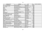
XVI- Revision log ................................................................................................................................. 43
CEA/DAM ♦ LMJ-PETAL User Guide ♦ 1
INTRODUCTION
I- Introduction
The Military Applications Division of the French Alternative Energies and Atomic Energy
Commission (CEA-DAM) has promoted for several decades collaboration with national and international
scientific communities [1-31]. Regarding laser facilities, according to the decision of the French Ministry of
Defense, the CEA-DAM has given access to the scientific communities to the LIL facility, the prototype of
Laser Megajoule (LMJ), for a period of 9 years since 2005 until 2014. Ten types of experimental campaigns
and a total of one hundred laser shots on targets in collaboration have been performed on the LIL during this
period [32-37]. With the LMJ [38] and PETAL facilities [39], the CEA-DAM is once again in a position to
welcome national and international teams, in perfect accordance with its legal obligations to confidentiality.
LMJ
LIL
Figure I.1 : LIL and LMJ aerial view
The Laser Megajoule is part of the French “Simulation Program” developed by the CEA-DAM. The
Simulation program aims to improve the theoretical models and data used in various domains of physics, by
means of high performance numerical simulations and experimental validations.
LMJ offers unique capabilities for the Simulation Program, providing an extraordinary instrument to
study High Energy Density Physics (HEDP) and Basic Science. A large panel of experiments will be done
on LMJ to study physical processes at temperatures from 100 eV to 100 keV, and pressures from 1 Mbar to
100 Gbar. Among these experiments, Inertial Confinement Fusion (ICF) is the most exciting challenge, since
ICF experiments fix the most stringent specifications on LMJ’s performances [40, 41].
The PETAL project consists in the addition of one high-energy multi-Petawatt beam to LMJ. This
project is being performed by the CEA under the financial auspices of the Aquitaine Region
("maître d'ouvrage", project owner), of the French Government and of the European Union. PETAL will
provide a combination of a very high intensity beam, synchronized with the very high energy beams of LMJ.
LMJ-PETAL will be an exceptional tool for academic research, offering the opportunity to study matter in
extreme conditions.
LMJ-PETAL will be open to the academic communities, as the previously mentioned LIL. The
academic access to LMJ-PETAL and the selection of the proposals for experiments will be done by Institut
Laser & Plasmas (ILP) through the PETAL international Scientific Advisory Committee.
This document provides the necessary technical references to researchers for the writing of Letter of
Intent (LOI) of experimental proposals to be performed on LMJ-PETAL. Regularly updated version of this
LMJ-PETAL User guide will be available on LMJ website at http://www-lmj.cea.fr.
CEA/DAM ♦ LMJ-PETAL User Guide ♦ 2
LMJ-PETAL OVERVIEW
II- LMJ-PETAL Overview
LMJ is now under commissioning at CEA-CESTA at a stage of 176 beams (44 quads).
LMJ is a flashlamp-pumped neodymium-doped glass laser (1.053 µm wavelength) configured in a
multi-pass power amplifier system. The 1.053 µm light is frequency converted to the third harmonic
(0.351 µm) and focused, by means of gratings, on a target at the center of the target chamber. LMJ will
deliver shaped pulses from 0.7 ns to 25 ns with a maximum energy of 1.5 MJ and a maximum power of
400 TW of UV light on the target.
The main building includes four similar laser bays, 128-meter long, situated in pairs on each side of
the central target bay of 60-meter diameter and 38-meter height.
The 176 square 37 x 35.6 cm2 beams are grouped into 22 bundles of 8 beams. In the switchyards, each
individual bundle is divided into two quads, the basic independent unit for experiments, which are directed to
the upper and lower hemispheres of the chamber.
PETAL beamline
Target chamber
Switchyards
Spatial filters
4-pass Amplifiers
Deformable
mirror
Power conditioning
modules
Pre-Amplifier
Modules
Diagnostics
rooms
Control room
N
Figure II.1: Schematic view of the Laser Megajoule showing the main elements of the laser system
At the center of the target bay, the target chamber consists of a 10-meter diameter aluminum sphere,
equipped with two hundred ports for the injection of the laser beams, the location of diagnostics and target
holders. It is a 10 cm-thick aluminum sphere covered with a neutron shielding made of 40 cm thick borated
concrete. The inside is covered by protection panels for X-ray and debris.
LMJ is configured to operate in the “indirect drive” scheme, which drives the laser beams into cones
in the upper and lower hemispheres of the target chamber. Forty quads enter the target chamber through
ports that are located on two cones at 33.2° and 49° polar angles. Four other quads enter the target chamber
at 59.5° polar angle, and will be dedicated to radiographic purpose.
The 44 laser beam ports include the final optics assembly: vacuum windows, debris shield and device
to check the damages on optics.
A lot of equipments is required in the target area:
• a Reference Holder (RH) is used for the alignment of all beams, diagnostics and target,
• a Target Positioning Systems (TPS) for room temperature experiments is operational,
• a cryogenic TPS for ignition target will be installed later,
CEA/DAM ♦ LMJ-PETAL User Guide ♦ 3
LMJ-PETAL OVERVIEW
• a set of visualization stations for target positioning (SOPAC stations, as System for Optical
Positioning and Alignment inside Chamber),
• a set of about ten Systems for Insertion of Diagnostic (SID) will be installed, they will position 150-kg
diagnostic with a 50-µm precision.
The PETAL project consists in the addition of one short-pulse (500 fs to 10 ps) ultra-high-power,
high-energy beam (few kJ) to LMJ. PETAL will offer a combination of a very high intensity multi-petawatt
beam, synchronized with the nanosecond beams of LMJ. PETAL will expand the LMJ experimental field on
HEDP.
The PETAL design is based on the Chirped Pulse Amplification (CPA) technique combined with
Optical Parametric Amplification (OPA). Furthermore, it takes the benefits of the laser developments made
for the high-energy LMJ facility allowing it to reach the kilojoule level.
Over 30 photon and particle diagnostics are considered with high spatial, temporal and spectral
resolution in the optical, X-ray, and nuclear domains. Beside classical diagnostics, specific diagnostics
adapted to PETAL capacities will be available in order to characterize particles and radiation yields that can
be created by PETAL [42]. The development of PETAL diagnostics takes place within the Equipex project
PETAL+ funded by the French Research National Agency (ANR) within the framework of the “Programme
d’Investissement d’Avenir” (PIA) of the French Government.
The first CEA-DAM physics experiments on LMJ have been performed at the end of 2014 with a
limited number of beams and diagnostics. The operational capabilities (number of beams and plasma
diagnostics) will increase gradually during the following years. The first academic experiments on LMJPETAL will be performed in 2017 with 16 beams (4 quads) and PETAL beam, 3 SID and 12 diagnostics.
History
Beginning of the construction of the LIL facility
First laser shots on LIL
Beginning of the construction of the LMJ facility
First target physics experiments on LIL
Beginning of PETAL on LIL
First academic experiments on LIL
LMJ target chamber installed
LMJ building commissioning
Decision of coupling PETAL with LMJ
Last academic experiments on LIL & closure of LIL
First target physics experiments on LMJ with 2 quads
First test shots on PETAL
First academic experiments on LMJ with 4 quads and PETAL
Date
1996
2002
2003
2004
2005
2005
2006
2008
2010
2014
2014
2016
2017
Table II.1: History of LIL, LMJ and PETAL facilities,
from the beginning of the LIL to the academic opening of LMJ-PETAL
CEA/DAM ♦ LMJ-PETAL User Guide ♦ 4
POLICIES AND ACCESS
III- Policies and Access to CEA-CESTA and LMJ facility
III.1- Driving directions and accommodations
The LMJ-PETAL facility is located at CEA-CESTA, 15 avenue des Sablières, CS 60001, 33116 Le
Barp Cedex, France. GPS coordinates are given in the appendix.
In Figure III.1, directions are given for visitors traveling from either the Bordeaux Merignac Airport,
or SNCF Bordeaux railway station. The A63 highway provides direct access to CEA-CESTA. The driving
distance from Bordeaux is 35 km, approximately 30 minutes in normal traffic conditions. Note that it is
compulsory that all visitors satisfy the badging policy described in the paragraph III.2-.
Figure III.1: Map of Bordeaux South area and transportation routes to CEA-CESTA and LMJ
There are some hotels close to CEA-CESTA, but numerous hotels can be found in the city of
Bordeaux or in the area of Arcachon (seaside). A list of hotels is given in the appendix.
CEA/DAM ♦ LMJ-PETAL User Guide ♦ 5
POLICIES AND ACCESS
III.2- Office space at ILP Campus and Computer access
To provide comfortable working conditions to worldwide researchers preparing their experiments, the
“Institut Laser & Plasmas” (ILP) and CEA-CESTA offer a large office space, Internet access and
administrative assistance inside the ILP Campus Building. This building is located just outside CEACESTA. Meeting rooms are available as well as a 150 places amphitheater which could be used for
workshops. The ILP building is located only 2 km away from LMJ Control Room. A cafeteria for lunch is
also accessible at walking distance, as well as supermarket, restaurants and food services located in Le Barp
city, 3 km away.
Figure III.2: Photograph of the ILP Campus building located on the open zone and only 2 km
away from LMJ-PETAL building
III.3- CEA-CESTA Access and regulations
CEA-CESTA is a national security laboratory with regulated entry. Visitors must make prior
arrangements at least 8 weeks before any visit. The experimental campaigns on LMJ-PETAL will be planned
at least 6 months in advance, and the access to CEA-CESTA could be extended up to a 3 months period. In
order to gain admittance, the requested information is the following:
Last name, first name, place of birth, nationality (dual nationality if any), nationality of birth, passport
number and date of validity (CNI number and validity for French citizen), home address, name and address
of employer, research institution, funding agency, professional phone number, professional email, contact in
case of emergency.
Please notice that access to LMJ-PETAL is of CEA responsibility only. Acceptance of an
experimental proposal by ILP doesn’t automatically grant access to CEA for all of the collaborators.
According to confidentiality rules, no justifications would be given in case of denied access to the facility.
Professional computers may be authorized on-site provided that the MAC address and physical
address of the computer were given with the aforementioned personal information. Internet connectivity will
be provided in a dedicated room; however no Wi-Fi capabilities are available inside CEA-CESTA.
All types of cellular telephones are forbidden. This restriction also applies for CEA people inside
restricted areas, like the LMJ-PETAL building. The cell phones should be kept secured in a cell phones
garage at the badging center entry.
III.4- Confidentiality rules
The CEA-DAM would be pleased to promote a wide participation of the academic communities to the
scientific and technologic researches which will be performed on the LMJ-PETAL facility. However, as an
organism which is in charge for the control of scientific disciplines involved in nuclear deterrence, the CEADAM has to follow the protection rules regarding National Defense.
As a consequence, some information and data obtained from laser experiments have to be protected
*
according to the “Guide on the sensitiveness of information in the field of Inertial Confinement Fusion” .
*
General Secretary for Defense and National Security: Document #3235/SGDSN/AIST of May 30, 2012
CEA/DAM ♦ LMJ-PETAL User Guide ♦ 6
POLICIES AND ACCESS
That is why some indications are given below to prevent or reduce any risk of reject of proposal
according to confidentiality rules.
Most of research themes can be carried out on LMJ-PETAL without any restriction: optics, laserplasma interaction, plasma physics, particles transport, thermal conduction, mechanics in continuous media,
general hydrodynamics, nuclear physics, etc.
Some other research fields are considered as sensitive: Equation of State (EOS), atomic spectra and
opacities, constitutive relations and damage laws of materials, radiative hydrodynamics, turbulent
hydrodynamics, X-ray radiation transfer, mixing physics in convergent flows, actinides studies, etc.
Some specific studies included in the previous list may be considered not sensitive. EOS and opacities
are notably concerned.
Regarding EOS and constitutive relations and damage laws, simple elements or mixture can be studied
at any pressure if their atomic number is lower or equal to 71. For atomic number between 72 and 91
(included), the pressure is limited to 1000 GPa. For atomic number greater than 91, the domain is considered
as sensitive at any pressure.
Atomic spectra and opacities can be studied for any temperature for element whose atomic number is
lower or equal to 36. For other elements, the temperature is limited to 50 eV.
The open domains for experiments are summarized in the figure III.3.
Pressure
(GPa)
Sensitive
domain
1000
Temperature
(eV)
Sensitive
domain
50
Open domain
71
Open domain
91 Atomic number (Z)
36
Atomic number (Z)
Figure III.3: a) Accessible pressure and atomic number for Equation of State experiments
b) Accessible temperature for opacities experiments
III.5- Selection process
A call for proposals for experiments on the LMJ-PETAL laser facility will regularly be issued on an
annual basis by ILP, CEA and Aquitaine Region.
Depending on the experiment complexity, experiments will be approved on a one-year or two-year
basis. The more complex selected experiments will be given a few laser shots in the first year, intended to
demonstrate the feasibility of the experiment. On the basis of the results of the campaign of the first year,
more laser shots will be assigned on the second year.
The selection process for experimental proposals on LMJ-PETAL is the following:
• First a Letter of Intent (LOI) should be addressed by research groups to ILP (Z.A. Laseris – 1 avenue du
Médoc – F-33114 Le Barp, [email protected]). This LOI should describe the
purpose of the experiment, the research groups involved in the experiment, the laser requirements
(energy, power, pulse shape, etc.), the diagnostic requirements, the target requirements, the number of
laser shots requested (limited to 6 per campaign).
A pre-selection of the most pertinent experiments will be done by the International Scientific Advisory
Committee of PETAL, established by ILP.
• Secondly, a full proposal should be sent to ILP ([email protected]) and CEADAM ([email protected]) by the pre-selected groups.
This report will include:
1. The experimental configuration at the target chamber center, including realistic target dimensions
and position of additional targets (backlighter if any).
2. The laser configuration
CEA/DAM ♦ LMJ-PETAL User Guide ♦ 7
POLICIES AND ACCESS
2.1. For LMJ beams:
- The desired spot sizes (see Table V.2) and Optical Smoothing Conditions (2 GHz or 2 + 14 GHz);
- The laser pulse shape per quad (P (TW) as a function of time) and Energy (kJ) per quad (the EnergyPower diagram is presented in Figure V.9);
- The laser aim points per quad.
2.2. For PETAL beam:
- Pulse duration (between 0.5 and 10 ps);
- Energy (the current transport mirrors limit the available energy on target at 1 kJ for the 2017-2018
timeframe);
- Best focus position.
3. The Diagnostic Configuration
The primary and secondary diagnostics for the physics goal must be specified.
Concerning Diagnostics in SID: 3 SID are available in the 2017-2018 timeframe. The Table VII.1.
indicates the available locations.
The fixed diagnostics, if needed, are: DMX in MS8, SESAME 1 and SESAME 2
4. The Target description
Sketch of the targets, including their dimensions, and the manufacturer of the targets must be
provided. The CEA target laboratory will be in charge of the alignment of the targets at target center
chamber (TCC).
5. The Preliminary Nuclear Safety analysis
In order to later fulfill the CEA LMJ nuclear safety rules, the following information are required:
- A rough estimate of the X-ray and/or electrons and/or ions emitted spectra, with their angular
distribution;
- The list of all the constitutive target materials with estimated mass.
6. Preparation requirements
The list of the experimental capabilities which need to be commissioned prior to the physics
experiment is requested: specific ns shaped pulse, PW laser contrast, characterization of specific hard
X-ray or proton backlighting sources, etc.
7. Shots logic and Draft Failure Modes
The order of the shots (6 shots per campaign at maximum) is required, as well as the logic of the shots
and the main possible failure modes (and back up plan).
Final selection of the most pertinent experiments is done by the International Scientific Advisory
Committee of PETAL in accordance with CEA-DAM.
III.6- Experimental process
Once the experiments have been selected, the experimental campaigns are included in the schedule of
the facility by the CEA-DAM Programming Committee. The selected groups are informed of this planning
approximately 2 years in advance of the experimental campaign. At the same time, Experiment Managers
from CEA (MOE, see III.7) are designated in order to prepare the experiment in close collaboration with the
selected groups.
The key milestones in the PETAL-LMJ experimental process will include several reviews in order to
evaluate the experimental preparations and readiness.
• The Launch Review is conducted approximately 24 months in advance of the experimental campaign.
The selected group, assisted by the MOE, presents the experiment proposal in front of CEA-DAM
experts. The primary purpose of this review is to ensure the proposed experiment meet the LMJPETAL requirements and to identify additional studies. CEA-DAM will analyze the proposals in
terms of confidentiality rules, security rules and feasibility. At this point CEA-DAM could ask the
CEA/DAM ♦ LMJ-PETAL User Guide ♦ 8
POLICIES AND ACCESS
research group to amend their proposal if it does not match the rules or if a feasibility matter is
identified.
Following the Launch Review, the selected groups will prepare a detailed report to be sent to CEA-DAM
([email protected]) approximately 18 months in advance of the experimental campaign. This report will
complete the full proposal with feasibility studies, simulation results (including X-ray and particles
emissions), detailed target description, etc.
• A Follow-up Review occurs approximately 6 months later. The selected group exposes the advances
of the experimental preparations and results of identified extra studies. This review is based on the
abovementioned detailed report. Depending on the progresses made, other Follow-up Reviews may be
scheduled.
• The Design Review is conducted approximately 12 months in advance of the experimental campaign.
In addition to the previous specified data’s (laser and diagnostic configurations, target description,
shots logic …), this review provides all information required by the facility: consideration of target
debris, nuclear safety analysis, diagnostics predictions, etc.
• The Readiness Review occurs approximately 1 month prior to the date of the experiment. It is the
final check to ensure that all preparations for execution of the experiment are complete.
III.7- Responsibilities during Shot Cycle
Several people will be in charge of the management of the experiment, each of them having a specific
responsibility.
The Principal Investigator (PI) is in charge of the scientific design of the experiment; he may be
assisted by a co-PI from ILP (for ICF studies for instance).
The practical design of the experimental project, taking into account the facility capabilities and the
expected results (laser energy, pulse shape, laser beams, diagnostics, alignment, debris from target, etc.)
comes under the responsibility of the CEA Experiment Manager (MOE); he will work in close collaboration
with the PI.
The making of the experimental campaign is under the responsibility of the CEA Experiment
Coordinator (RCE); he is in charge of the target and laser bay functioning and performances taking into
account all inherent risks for the operation crew and material.
The laser shots during the campaign are under the responsibility of the LMJ Shot Director who is
responsible for the LMJ safety.
The PI will not be in direct contact with the LMJ Shot Director. Decisions related to the effective
performance of the experimental campaign are taken according to the PI’s wishes; however communications
with the Facility and LMJ Shot Director are the sole responsibility of the MOE and RCE.
III.8- Access to LMJ-PETAL during shots
Access to the LMJ-PETAL facility requires half-day training to LMJ security rules and general
information. This course is usually given on Monday.
To ensure personnel and equipment safety, it is mandatory that the LMJ Control Room remains a quiet
area during shot operations. Shot preparation is a long process and will take a few hours which include some
phases not relevant for physicists. A dedicated meeting room will be available close to the LMJ Control
Room for the PI for the final shot phase when his presence is necessary.
To limit administrative duties and escort procedures, the number of external users allowed to follow
one shot is limited to 4 people maximum, typically the PI, co-PI (if any), one PhD student and diagnostics
expert (for PETAL+ diagnostics for instance). Those people could rotate during the week or the experimental
campaign (providing the access procedures have been followed).
CEA/DAM ♦ LMJ-PETAL User Guide ♦ 9
POLICIES AND ACCESS
Figure III.4: View of the LMJ Control Room
III.9- Data access
The laser pulse shapes and raw laser energy are immediately observable after the shot, like X-ray
images acquired on X-ray framing camera or streaked camera when they are directly recorded on electronic
devices (CCD). The consolidated laser energy will be communicated at the end of the experimental
campaign because it requires evaluation of the vacuum window transmission which could have been
modified by laser-induced damages. For data requiring digitizing or scan (like Image Plate) the data release
will not be possible immediately after the shot, but a few hours later. It is also the case for data depending on
material handling inside target bay area, which is regulated by safety procedures for contamination control
and radiation monitoring.
Raw experimental data and/or data translated into physics units will be accessible to the PI and his
experimental team as soon as possible after the shot. The data release is of CEA responsibility. The release
of detailed response functions of some diagnostics, like for example the detailed response functions of
DMX-LMJ channels, may be considered as classified information. This is why only consolidated data in
physics units will be delivered to the PI in such a case. By any way the CEA Experiment Manager will
ensure that all essential physics data are delivered to the PI. He is responsible for the quality of the
experimental data.
Data support will be either USB keys for the data directly available after the shot or CD-ROM for
consolidated and scanned data. The baseline data format of LMJ data is a custom hdf5. CEA will provide
hdf5 structure description and if necessary basic tools to extract the information.
III.10- Publications and Authorship practices
Results of LMJ-PETAL experiments are expected to be published in major journals and presented in
scientific conferences. The PI should inform CEA-DAM of any publication a few weeks before any major
conference (APS DPP, IFSA, EPS, ECLIM, ICHED, HEDLA, HTPD, etc.) using the email address
[email protected]. It is of PI responsibility to judge who made a significant contribution (or only a minor) to
the research study. However CEA Experiment Manager (MOE) and CEA Experiment Coordinator (RCE), as
well as CEA Diagnostics leaders, should be co-authors of the first publications of the campaign they have
been involved in. A statement acknowledging the use of LMJ-PETAL should be included in all publications.
The sources of financial support for the project (ANR, ILP, ERC) should also be disclosed.
CEA/DAM ♦ LMJ-PETAL User Guide ♦ 10
LMJ BUILDING DESCRIPTION
IV- LMJ Building description
The LMJ building covers a total area of 40 000 m2 (300 m long x 100 to 150 m wide). It includes four
similar laser bays, 128 meters long, situated in pairs on each side of the central target bay. The target bay is a
cylinder of 60-meters diameter and 38-meters height, with a 2-meters thick concrete wall for biological
protection.
At the center of the target bay, the target chamber consists of a 10-meters diameter aluminum sphere,
fitted with two hundred ports for the injection of the laser beams and the location of diagnostics and target
holders. The four lasers bays, completed by the end of 2013, are now equipped with all the supporting optics
infrastructures and the final optical components are currently being installed.
The PETAL laser beam takes the place of one classical LMJ bundle inside the South-East laser Bay.
N
N-O Laser bay
(5 bundles)
N-E Laser bay
(5 bundles)
S-O Laser bay
(5 bundles)
S-E Laser bay
(7 bundles + PETAL)
Target bay
100 m
Switchyard
PETAL beam line
300 m
Ø = 60 m
H = 38 m
Figure IV.1: a) Drawing of the building with total dimensions
b) CAD of the target bay with transport of the beams, the experimental chamber and its equipment: target
positioning system, plasma diagnostics
CEA/DAM ♦ LMJ-PETAL User Guide ♦ 11
LMJ LASER SYSTEM
V- LMJ Laser system
V.1- Laser architecture
LMJ is under commissioning at CEA-CESTA at a stage of 176 beams. LMJ is a flashlamp-pumped
neodymium-doped glass laser (1.053 µm wavelength) configured in a multi-pass power amplifier system.
The LMJ 3100 glass laser slabs will be capable of delivering more than 3 MJ of 1.053 µm light, that is
subsequently frequency converted to the third harmonic (0.351 µm) and focused on a target at the center of
target chamber. LMJ will deliver shaped pulses from 0.7 ns to 25 ns with a maximum energy of 1.5 MJ and a
maximum power of 400 TW of UV light on target.
The architecture of one beamline is shown on Figure V.1. The front end delivers the initial light pulse
and provides its temporal and spatial shape as well as its spectrum and enables synchronization of all the
beams. The front end is made of four sources (one per laser hall), which deliver the first photons (about
1 nJ), and 88 Pre-amplifier Modules (PAM, 1 per 2 beams), including a regenerative cavity and an amplifier,
which deliver a 500-mJ energy beam to the amplification section.
Deformable
mirror
Amplification
Section
Pockels
Cell
Spatial
Filters
Transport,
Frequency conversion
and focusing
Angular
multiplexing
4 pass
amplifiers
Source
10 mJ
Front end
1 & 2w beam
dump
Target
Chamber
18 kJ
Regenerative
cavity
1 nJ
Frequency conversion
& focusing system
Phase
plate
Amplifier
Window +
debris shield
7.5 kJ UV
500 mJ
Transport
mirrors
Figure V.1: Architecture of one LMJ beamline.
The basic unit for experiment is a quad made of 4 identical beamlines
Figure V.2: PreAmplifier Module in the North-East Laser Bay
CEA/DAM ♦ LMJ-PETAL User Guide ♦ 12
LMJ LASER SYSTEM
Figure V.3: South-West Laser Bay equipped with 5 amplification sections
In the amplification section, the beams are grouped in bundle of 8 beams and they are amplified
30 000 times to reach energy of 15-18 kJ per beam. The amplification section includes two 4-pass amplifiers,
two spatial filters, a plasma electrode pockels cell, a polarizer and a deformable mirror for wavefront
correction.
Figure V.4: Mounting of 4 laser slabs, plasma electrode pockels cell and deformable mirror
In the switchyards, each individual bundle is divided into two quads, which are directed to the upper
and lower hemispheres of the chamber by the mean of 5, 6 or 7 transport mirrors. The quad is the basic
independent unit for experiments.
The LMJ target chamber is arranged with a vertical axis. LMJ is configured to operate usually in the
“indirect drive” scheme [41], which directs the laser beams into cones in the upper and lower hemispheres of
the target chamber. Forty quads enter the target chamber through ports that are located on two cones at 33.2°
CEA/DAM ♦ LMJ-PETAL User Guide ♦ 13
LMJ LASER SYSTEM
and 49° polar angles. Four other quads enter the target chamber at 59.5° polar angle, and will be dedicated to
radiographic purpose (see Figure V.5).
The PETAL beam enters the experimental chamber in the equatorial plane.
33.2° : 10 quads
49° : 10 quads
59.5° : 2 quads
90° : PETAL
120.5° : 2 quads
131° : 10 quads
146.8° : 10 quads
Figure V.5: Target chamber and geometry of the LMJ irradiation
A detailed configuration of irradiation geometry is given in Figure V.6 and the spherical coordinates
of all beam ports are given in Table V.1.
U
L
Upper quad
81°
99°
117°
Lower quad
135°
U
L
U
L
U
153°
U
L
U
L
L
U
171°
U
L
U
207°
Third operative
quads
ϕ
9°
L U
U
θ = 33.2° 49°59.5° 90°
L
U L
351°
U
PETAL
L
U
L
346.5°
U
189°
U
L
L
L
27°
U
L
L
First operative
quads in 2016
45°
63°
U
L
L
U
U
L
U
L
225°
L
L
U
315°
297°
243°
261°
333°
U
279°
Second
operative quads
Figure V.6: Irradiation geometry of LMJ quads and PETAL beam. The first operative quads are indicated
CEA/DAM ♦ LMJ-PETAL User Guide ♦ 14
LMJ LASER SYSTEM
Beam Port
θ
ϕ
Beam Port
θ
ϕ Beam Port θ
First quads operative in 2016
131°
81°
29U
49°
ϕ
Beam Port
θ
ϕ
28U
PETAL
33.2°
90°
81°
346.5°
28L
63°
29L
146.8°
63°
17U
10U
33.2°
49°
297°
207°
17L
10L
49° 279°
33.2° 225°
18L
11L
146.8° 279°
131° 225°
5U
22U
19U
13U
26U
2U
7U
21U
49°
49°
59.5°
33.2°
33.2°
33.2°
49°
33.2°
135°
351°
333°
261°
45°
117°
171°
333°
5L
22L
19L
13L
26L
2L
7L
21L
33.2°
33.2°
59.5°
49°
49°
49°
33.2°
49°
6L
24L
23L
14L
25L
3L
9L
20L
131°
131°
120.5°
146.8°
146.8°
146.8°
131°
146.8°
Next operative quads
131° 297°
18U
146.8° 207°
11U
Subsequent quads
146.8° 135°
6U
146.8° 351°
24U
120.5° 315°
23U
131° 261°
14U
131°
45°
25U
131° 117°
3U
146.8° 171°
9U
131° 333°
20U
153°
9°
9°
243°
27°
99°
189°
315°
153°
9°
351°
243°
27°
99°
189°
315°
Table V.1: Spherical coordinates of beam ports
V.2- LMJ Frequency conversion and focusing scheme
The optics assembly for frequency conversion and focusing is composed of a 1ω grating, two KDP
crystals for Second and Third Harmonic Generation, and a 3ω focusing grating. The 1ω grating deflects by
an angle of 50° the incoming 1ω beam. An angular dispersion of the spectrum is introduced by the grating
which allows broadband frequency tripling. The frequency converters use a Type I-Type II third harmonic
generation scheme. The 3ω grating deflects back the 3ω beam by an angle of 50°, while the unconverted
light is stopped by absorbers. As a consequence no volume restrictions and additional shielding for
unconverted light issues have to be taken into account in the making of the experiments.
3 ω focusing
grating
4 x 15 kJ at
1.05 µm
Phase plate
Beam dump for
blocking 1 ω and 2 ω
3 ω focusing gratings
(40x40 cm2)
3ω
diagnostics
1 ω grating
KDP crystals
Protective
optic
Vacuum window
4 x 7.5 kJ at 0.35 µm
on target at 8m
Figure V.7: LMJ frequency conversion and focusing by gratings
The pointing accuracy of LMJ quadruplets depends on the aim point. Two pointing volumes have been
defined. The finest accuracy (50 µm rms) is achieved inside a 30 mm diameter x 30 mm high orthocylinder
(see Figure V.8). Outside this first cylinder the pointing volume can be described by two other imbricated
cylinders with a 75 to 100 µm pointing accuracy. These capabilities have to be considered for the positioning
of X-ray backlighters for instance.
CEA/DAM ♦ LMJ-PETAL User Guide ♦ 15
LMJ LASER SYSTEM
Upper quads
30 mm
75 µm
100 µm
30 mm
100 mm
Pointing
volume
30 mm
50 µm
75 µm
30 mm
± 35 mm
Precise pointing
volume
75 µm
100 µm
100 mm
Lower quads
Figure V.8: LMJ pointing volume and expected pointing accuracy (rms)
V.3- Beam Smoothing
To reduce the peak intensity of the light on the target, several techniques are available on LMJ:
continuous phase plate (see paragraph V.4) and smoothing by spectral dispersion.
Two phase modulations at 2 GHz and 14 GHz around the central wavelength are realized. The first
one (2 GHz) is used to raise the threshold of appearance of the Brillouin effects in optics at the end of the
laser chain. The second one (14 GHz) is dedicated to Smoothing by Spectral Dispersion (SSD). The full
bandwidth available with both frequency modulations is 0.5 nm at 1ω in order to reduce the contrast in the
speckles of the focal spot on the target down to 20% [43].
Due to the specific LMJ focusing system, the movement of speckles in the focal spot is along the laser
axis (longitudinal SSD) instead of being perpendicular to this axis (transverse SSD) as in standard laser
facilities.
Another smoothing technique, polarization smoothing, will be installed later for ignition experiments.
V.4- Spot sizes
Various Continuous Phase Plates (CPP) could be considered for the spot sizes. Three types have been
defined for the first phase of operations with circular focal spots, called CPP Type D, Type E and Type F.
The nominal phase plate is the Type D for heating the target. The Type E provides a larger focal spot
for uniform irradiation (direct drive EOS experiments or large backlighter). The Type F provides a smaller
focal for radiography purposes.
The peak intensity on target for a 5 TW pulse, the diameters of focal spots at 3 % of the peak intensity
and the order of the super-Gaussian describing the intensity profile are given in the Table below.
CPP
Diameters at 3 %
(µm)
Intensity (5 TW)
(W/cm2)
Super-Gaussian
Order
Type D
940
1.8 1015
2.6
Type E
1500
5.8 1014
3.5
Type F
630
6 10
15
TBD
Table V.2: Characteristics of standard Continuous Phase Plates
CEA/DAM ♦ LMJ-PETAL User Guide ♦ 16
LMJ LASER SYSTEM
V.5- Energy and Power
The available laser energy for user experiments is constrained by optical damages on gratings [44] and
vacuum windows and operating costs. Whereas LMJ nominal laser energy is designed for 30 kJ per quad for
ignition experiments, a lot of CEA experiments will be performed at limited laser energy to reduce the
optical damages on final optics. Experimental designs with 10 to 15 kJ per quad are to be considered.
The maximum sustainable laser energy for a given pulse shape will be refined with feedbacks from
laser scientists [45, 46] during the preliminary design review of an experiment. Operational limits depend on
the exact pulse shape and the type of CPP.
The figure V.9 gives the maximum performances and the recommended setting as a function of pulse
duration for square pulses.
10
0.7 ns
1 ns
2 ns
3 ns
Power per quad (TW)
8
5 ns
6
7 ns
4
10 ns
2
20 ns
0
0
5
10
15
20
25
Energy per quad (kJ)
30
35
40
Figure V.9: LMJ sustainable operational energy and power limits. The red line is the maximum
performances; the green line is the recommended setting in order to limit damage on optics [9]
During the first experiments performed in 2014, the LMJ facility has proved a shot to shot
repeatability of the delivered energy per quad better than 3 %.
V.6- Pulse shaping capabilities
The LMJ source (master oscillator) is designed to deliver complex ignition pulse. As a consequence, a
wide variety of pulse shapes can be produced on LMJ, with a minimum duration of 0.7 ns and a maximum
duration of 20 ns. Complex pulse shapes (rising pulse, decreasing pulse, multiple pulse, with pedestal, etc.)
can be fashioned, but will required some test laser shots for a fine tuning [46]. Some examples of pulse
shapes are given in figure V.10 and V.11.
All the LMJ beams will be synchronized at the center of the target chamber within a standard
deviation of 40 ps.
CEA/DAM ♦ LMJ-PETAL User Guide ♦ 17
LMJ LASER SYSTEM
Figure V.10: Different envisioned pulses shapes for ignition target (in red and blue).
The dashed black lines are supergaussian used to fit each specific part of the pulse
Figure V.11: Typical pulse shape realized on the LIL facility for isentropic compression experiments [37]
(request in red)
On LMJ, the Pre-Amplifier Module (PAM) is common for two beams within one quadruplet. However
as the two PAMs of a single quadruplet share the same master oscillator (see Figure V.12), only one pulse
shape is available per quadruplet. This versatility in pulse shaping will be beneficial for Polar Direct Drive
Shock Ignition [47]. Delays between quadruplets could be defined for example to use one quadruplet as the
main driver and one quadruplet to irradiate an X-ray backlighter. The maximum available delays are
currently limited to 100 ns.
CEA/DAM ♦ LMJ-PETAL User Guide ♦ 18
LMJ LASER SYSTEM
Figure V.12: Schematic of the pulse shaping capability within a LMJ bundle (2 quads, 8 beams)
V.7- Laser performances
The first LMJ experiments were carried out in October 2014, with the 8 initial beams (28U and 28L).
They revealed good performances of the whole system.
The pointing accuracy of the quad was 50.6 ± 23 µm (compare to a 100 µm specification), and the
beams synchronization was about 20 ps (compare to a 100 ps specification).
The figure V.13 shows the history of energy delivered on the target for the eight shots of this first
physics campaign. The mean energy obtained over the eight shots is 19.92 kJ ± 0.16 per chain, to compare
with the 20 kJ (2.5 kJ x 8) required.
Energy (kJ)
12
10
8
Upper Quad
6
Lower Quad
4
2
0
1
2
3
4
5
6
7
8
Figure V.13: History of the energy delivered on the target for the eight first shots (October 2014)
For these 8 experiments, the achieved pulse durations present a good reproducibility: 2.85 ± 0.1 ns
(see Figure V.14).
CEA/DAM ♦ LMJ-PETAL User Guide ♦ 19
LMJ LASER SYSTEM
Power (TW)
4,5
4,0
3,5
3,0
15/10/2015
2,5
17/10/2015
2,0
28/10/2015
1,5
29/10/2015
1,0
30/10/2015
0,5
0,0
-1
0
1
2
Time (ns)
3
4
5
Figure V.14: Pulse shapes of the first physics campaign on LMJ (for clarity only 5 of them are shown)
CEA/DAM ♦ LMJ-PETAL User Guide ♦ 20
PETAL LASER SYSTEM
VI- PETAL Laser system
The PETAL design is based on the Chirped Pulse Amplification (CPA) technique combined with
Optical Parametric Amplification (OPA) [48-50]. Moreover, it takes the benefits of the laser developments
made for the high-energy LMJ facility allowing it to reach the kilojoules level.
Figure VI.1 shows the implementation of PETAL in the LMJ facility. The PETAL beamline occupies
the place of a LMJ bundle in the South-East laser bay. The compressor stages are situated at the bottom level
of the target bay, and after a transport under vacuum, the beam is focused in the equatorial plane of the LMJ
chamber via an off-axis parabolic mirror.
Focusing parabola
LMJ bundles
PETAL beamline
Compression stages
Fig. VI.1: Implementation of PETAL in the LMJ facility.
The PETAL beam is focused in the equatorial plane of the target chamber
The front end consists in a standard Ti:sapphire mode locked oscillator delivering 3nJ /100 fs / 16 nm
pulse at 77.76 MHz and 1053 nm wavelength. The pulse is stretched to 9 ns in an Öffner stretcher in eight
passes. Then the pulse is sent to the Pre-Amplifier Module (PAM) including OPA stages and pump laser.
The OPA scheme consists of two cascaded LBO crystals and a BBO crystal. A 150 mJ amplified signal pulse
with a shot-to-shot stability of less than 2% has been demonstrated on the LIL facility [49, 50].
The PETAL amplifier section has the same architecture as the LIL/LMJ amplifier section using a
single 37 × 35.6 cm2 beam. It is a four-pass-system with angular multiplexing and a Reverser. It uses 16
amplifier laser slabs arranged in two sets and delivering up to 6 kJ. At this stage, due to gain narrowing, the
bandwidth is reduced to 3 nm and duration to 1.7 ns. The main differences with the LIL/LMJ power chain
are the wavefront and chromatism corrections [51].
The compression scheme is a two-stage system (see Figure VI.2). The first compressor, in air
atmosphere, reduces the pulse duration from 1.7 ns to 350 ps in an equivalent double pass configuration. The
output mirror is segmented in order to divide the initial beam into 4 sub-apertures which are independently
compressed and synchronized into the second compressor in a single pass configuration under vacuum [52].
These sub-apertures are coherently added using the segmented mirror with three interferometric
displacements for each sub-aperture. The pulse duration is adjustable from 0.5 to 10 ps.
The focusing system consists in an off-axis parabolic mirror with a 90° deviation angle, followed by a
pointing mirror (see Figure VI.3). The focal length is 7.8 meters, and the focal spot goal is a 50 µm diameter,
this will result in intensities above 1020 W/cm2 on target. Due to the 4 sub-apertures of the beam [53], a
multi-beam option could be available: a segmented pointing mirror could redirect the beams towards up to 4
separate focuses. This option will be studied in detail if required.
CEA/DAM ♦ LMJ-PETAL User Guide ♦ 21
PETAL LASER SYSTEM
500 fs
3 kJ
Segmented mirror
Diagnostics room
350 ps
4.4 kJ
1.7 ns
6 kJ
2nd stage
Vacuum compressor
1st stage
Figure VI.2: Compressor stages with a subaperture compression scheme: first stage in air and second stage
in vacuum with 4 independent compressors
Pointing
mirror
Off-axis
parabola
Alignment
mirror
Figure VI.3: PETAL beam and LMJ bundles in the South-East laser bay, and PETAL focusing scheme
The PETAL performances depend on the damage threshold of optics. Great efforts have been made on
gratings in order to improve their strength. The effect of electric field on damages has been demonstrated
[54], and the groove profile of PETAL multilayer dielectric gratings has been optimized in order to obtain a
damage threshold above 4 J/cm² in the ps range. But in fact, the transport mirrors may not sustain more than
2 J/cm² compared to the 4 J/cm² specified value required for a 3 kJ output level. Therefore, the current
mirrors will first limit the available energy on target at a 1 kJ level. New technologies are required to
increase this value and the intensity on target. Several ways of improvement are identified and are being
explored.
CEA/DAM ♦ LMJ-PETAL User Guide ♦ 22
TARGET AREA AND ASSOCIATED EQUIPMENTS
VII- Target area and associated equipments
As shown previously in Figure IV.1, the target bay area occupies the central part of the building. There
are 8 floors. A detailed CAD of the target chamber with the major target bay equipments is shown in Figure
VII.1.
SID
Cryo TPS
SID
RH
Airlock
TPS
SID
SID
Robot
SID
Figure VII.1: CAD of the target area
The radius of LMJ target chamber is 5 meters. Beam and diagnostics ports cover the full surface. A
SID is provided on several different port locations for inserting diagnostics used to make measurements
during a target experiment on LMJ. A SID is a two-stage telescoping system that provides a precise
positioning of a diagnostic close to the center of target chamber. Two kinds of SIDs are available: the LMJ
SIDs are designed for ignition experiments, they provide the best positioning accuracy for imaging system,
can be positioned on polar axis, and use electronic detectors; the PETAL SIDs are dedicated to PETAL
diagnostics which use passive detectors due to electromagnetic perturbations induced by PETAL shots, and
cannot be positioned on polar axis. About 10 SIDs are envisioned for the LMJ.
The port locations of the target handling equipment (Reference Holder (RH), Target Positioning
System (TPS) and cryogenic TPS, SOPAC viewing stations) and the possible port locations for the different
SID are listed in the Table VII.1. Three Specific Mechanisms ports are also available, 2 of them (MS8 and
MS9) being reserved for DMX Broadband time-resolved spectrometer.
The diagnostics insertors locations are schematically drawn in Figure VII.3. Additional target chamber
ports for fixed diagnostics exist and may be considered for future diagnostics developments.
CEA/DAM ♦ LMJ-PETAL User Guide ♦ 23
TARGET AREA AND ASSOCIATED EQUIPMENTS
θ
ϕ
Remark
RH
TPS
Cryo TPS
SOPAC
SOPAC
SOPAC
SOPAC
SOPAC
SOPAC
SOPAC
SOPAC
90°
90°
90°
16°
24°
90°
90°
90°
90°
164°
164°
238.5°
255.5°
220.5°
9°
243°
13.5°
103.5°
193.5°
283.5°
9°
189°
Reference holder
Target Positioning System
Cryogenic TPS, unavailable
Target viewing station
Target viewing and lighting station
Target viewing station
Target viewing station
Target viewing station
Target viewing station
Target viewing and lighting station
Target viewing station
Diagnostics insertors
S1
S2
S3
S5
S7
S12
S16
S17
S20
S22
S26
16°
164°
16°
90°
164°
90°
90°
0°
90°
90°
90°
333°
Close to polar axis, unavailable
279°
Close to polar axis
153°
Close to polar axis, unavailable
112.5°
Unavailable
99° Close to polar axis, laser injection and collection for EOS Pack
148.5°
58.5°
0°
Polar axis
292.5°
Optical system of EOS pack
328.5°
PETAL+ SPECTIX diagnostic, Opposite S12
180°
PETAL+ SEPAGE diagnostic
Specific mechanisms
MS 8
MS 9
MS 18
SESAME 1
SESAME 2
24°
70°
90°
90°
90°
99°
72°
222°
166.5°
121.5°
Port
Target equipment
DMX position 1
DMX position 2
Activation diagnostic, unavailable
PETAL+ SESAME diagnostic position 1
PETAL+ SESAME diagnostic position 2
Table VII.1: Spherical coordinate of target equipment and diagnostics insertors.
The unavailable locations for experiments in 2017-19 are indicated
Figure VII.2 : Reference holder and Target positioning system
CEA/DAM ♦ LMJ-PETAL User Guide ♦ 24
TARGET AREA AND ASSOCIATED EQUIPMENTS
S17 (0°, 0°)
S1 (16°, 333°)
S3 (16°, 153°)
θ
S26 (90°, 180°)
S12 (90°, 148.5°)
S5 (90°, 112.5°)
Neutron
90°
S20 (90°, 292.5°)
S16 (90°, 58.5°)
S22 (90°, 328.5°)
0°
φ
S2 (164°, 279°)
S7 (164°, 99°)
Figure VII.3:3D view of the SIDs location on the target chamber. S1, S3 and S5 are unavailable in 2017-19.
S7 is dedicated to laser injection and collection for EOS Pack
Figure VII.4: View of the upper part of the target bay
CEA/DAM ♦ LMJ-PETAL User Guide ♦ 25
LMJ DIAGNOSTICS
VIII- LMJ Diagnostics
Over 30 diagnostics are considered with high spatial, temporal and spectral resolution in the optical,
X-ray, and nuclear domains. Plans for LMJ diagnostics began with LIL laser facility and rely on decades of
expertise in the design, fabrication and commissioning of advanced plasma diagnostics. The OMEGA laser
facility has also been used and will continue to be the test bed for the development of CEA nuclear
diagnostics. The early diagnostics, designed using the feedback of LIL’s diagnostics, consist of:
• four hard and soft X-ray imaging systems (30 eV to 15 keV range) with a 15 to 150 µm spatial
resolution and a 30 to 100 ps time resolution, providing 30 imaging channels,
• a diagnostic set for hohlraum temperature measurements including an absolutely calibrated broadband
X-ray spectrometer (30 eV - 20 keV), a grating spectrometer, a time resolved imaging system of the
emitting area,
• an absolutely calibrated broadband X-ray spectrometer (30 eV - 7 keV),
• an optical diagnostic set dedicated to EOS measurements including 2 VISAR (Velocity Interferometer
System for Any Reflector), 2 SBO (Shock Break Out), a pyrometer and a reflectivity measurement,
• a Full Aperture Backscatter System, and a Near Backscatter Imager to measure the power, spectrum,
and angular distribution of backscatter light to determine the energy balance.
The main characteristics of the first set of diagnostics are described in Table VIII.1.
X-ray Imagers
Diagnostics
& Setting
Characteristics
Spectral range
Spatial resol. (µm) / Temp. resol. (ps) /
Field of view (mm)
dynamic (ns)
Magnification = 4,4
2x4 toroidal mirror channels
0.5 - 10 keV
30 / 3 (15 / 1.5)
75 / 20
4 pinhole channels
2 - 15 keV
40 / 3
75 / 20
SID 1 time integrated mirror channel
without
SHXI
Magnification = 1 or 3
Streaked Hard X-ray
2 streaked toroidal mirror channels 0.5 - 10 keV
150 / 15 or 50 / 5
30-100 / 5-25
Imager (medium resol.)
5 - 10 keV
130 / 20 or 50 / 6,5
without
SID 2 time integrated lenses channels
Magnification = 0.9
GXI-2
2x4 toroidal mirror channels
0.5 - 10 keV 150 / 15 (100 / 10)
50 / 20
Gated X-ray Imager
(medium resolution)
4 X-ray lenses channels
6 - 15 keV
150 / 15
"
SID 1 time integrated mirror channel
without
SSXI
Magnification = 1 & 3
Streaked Soft X-ray
2 toroidal mirror channels
0.05 – 1.5 keV 30 / 5 & 50 / 15
50 / 5 to 250 / 25
Imager (high resolution)
Spectral selection by grating
SID
GXI-1
Gated X-ray Imager
(high resolution)
X-ray Spectrometers
Diagnostics
Spatial resol. (µm) / Temp. resol. (ps) /
Field of view (mm)
dynamic (ns)
20 broad-band channels
0,03 - 20 keV
- / (2-5)
100
0.1 – 1.5 keV
DMX
50
Grating X-ray spectrometer ∆λ<1Å
1.5 – 4 keV
Broad-band X-ray
spectrometer
Laser Entrance Hole Imager
0.5 - 2 keV
100 / 5
500
0.1 - 2 keV
Specific mechanics
X-ray Power
2.0 – 4.0 keV
- / (2-5)
100
4.0 – 6.0 keV
Mini-DMX
Broad-band X-ray
16 broad-band channels
0.03 – 7 keV
-/5
100
spectrometer
SID
& Setting
Characteristics
Spectral range
CEA/DAM ♦ LMJ-PETAL User Guide ♦ 26
LMJ DIAGNOSTICS
Optical diagnostics
Diagnostics
& Setting
EOS pack
Diagnostics set for EOS
experiments
SID (microscope)
FABS
Full Aperture
Backscattering Stations
Focusing system
NBI
Near Backscatter Imager
Chamber wall
Characteristics
Spectral range
2 VISAR (Infra-Red and Green)
Shock Break Out (SBO)
Pyrometer
Reflectivity
Image 2D : 2 or 4 images
Brillouin spectrometer ∆λ <
0.05nm
Raman spectrometer ∆λ < 5 nm
2 Brillouin power channels
2 Raman power channels
2 Brillouin power channels
0.5 - 200 km/s
2 Raman power channels
350-750 nm
Spatial resol. (µm) / Temp. resol. (ps) /
Field of view (mm)
dynamic (ns)
30 / 1 to 100 / 10
> 0.1 eV
0.01 à 1
> 1 eV
10 / 1 to 50 / 5
100 / 10
346-356 nm
50 / 5 to 500 / 100
< 10 or < 50 ps
50 / 5 to 500 / 100
75 - 200 / 5 - 20
50 / 5 to 250 / 25
350-750 nm
< 360 nm
350-750 nm
346-356 nm
250 / 25
2°/16°
1000/10
Table VIII.1: LMJ diagnostics names and their main characteristics
Companion Table-top laser facilities [55] or X-ray sources [56] are used to perform metrology of the
X-ray diagnostics before any plasma experiment.
VIII.1- X-rays imagers
The development of grazing-incidence X-ray microscopes is one of the skills of CEA diagnostics
development laboratory. On LMJ, shrapnel [57] and X-ray loading [58] impose to place any imager as far
away from the source as possible, which would degrade the spatial resolution. Grazing incidence X-ray
microscopes allow overpassing this limitation. Compared to standard pinhole imagers, they offer also the
best solution in terms of resolution versus signal to noise ratio. The design of LMJ X-rays imagers benefits
from years of expertise either on OMEGA [59] or LIL X-rays imagers [60, 61].
These imagers, either gated (GXI-1 and GXI-2) or streaked (SHXI and SSXI) share a common
mechanical structure (see Figure VIII.1) with the X-rays optical block itself, a telescopic extension and the
optical analyzer (X-ray framing camera or streaked camera) working inside an air box mechanical structure
(see Figure VIII.2) [62]. Diagnostics development takes into account the harsh environment [63] which will
be encountered on LMJ, as well as the electromagnetic perturbations induced by PETAL [64].
Figure VIII.1: Common mechanical structure of LMJ X-rays imager.
CEA/DAM ♦ LMJ-PETAL User Guide ♦ 27
LMJ DIAGNOSTICS
Figure VIII.2: Current design of LMJ optical analyzers [62]
The first LMJ X-ray imager GXI-1 has been commissioned on the facility in 2014. The optical block
of the diagnostic includes an integrated unit, consisting of three alignment lasers (see Figure VIII.3). The
optical scheme of the diagnostic is based on grazing incidence mirrors [65-68] together with a classical
pinhole imaging in the central part of the system. 12 time-resolved images and 1 time integrated image will
be acquired at the end, with different filtering options (see Figure VIII.4). Actual photographs of the GXI-1
diagnostic are displayed in Figure VIII.5.
Alignment lasers
Frame
MC mirrors
(GOI channels)
X-ray microscope
MC mirror
(CID channel)
Zerodur™ structure
Figure VIII.3: Current design of the optical block of LMJ GXI-1
CEA/DAM ♦ LMJ-PETAL User Guide ♦ 28
LMJ DIAGNOSTICS
Figure VIII.4: Details of the acquisition channels of LMJ GXI-1
Figure VIII.5: Photograph of GXI-1 and zoom on the optical block
VIII.2- DMX-LMJ: Soft X-ray broadband time-resolved spectrometer
DMX is a primordial diagnostic for hohlraum energetic performance measurements [69].
DMX diagnostic is composed of a set of four diagnostics:
• a time resolved Soft X-ray Large Band spectrometer made of 20 measurement channels
combining mirror, filters and X-ray diodes,
• a time resolved Soft X-ray spectrometer with gratings and streaked camera,
• a time resolved Soft X-ray Laser Entrance Hole Imaging with X-ray diodes array,
• a time resolved X-ray Power measurement spectrally integrated.
CEA/DAM ♦ LMJ-PETAL User Guide ♦ 29
LMJ DIAGNOSTICS
Vacuum
valve
Target chamber
interface
Filters box
(>200 unities)
X-ray
detectors
Streaked
camera
Collimator
Target
Telescopic arm
(collimators inside)
Gimbal
Bipod
Vacuum and nuclear
venting equipment
Length = 8 to 11 meters
Figure VIII.6: DMX diagnostic
Beside standard soft X-ray measurements devoted to hohlraum energetics, the filtration of the
channels could be adapted for specific purpose, such as conversion efficiency characterization of
backlighters [70-72].
However as those measurements may require additional filters metrology on synchrotron beam lines
(synchrotron SOLEIL at Saint Aubin), the request should be done well in advance.
Multilayer mirrors with spectral bandwidth are also under development for flat-response X-ray
channels [73].
Figure VIII.7: Photograph of DMX during qualification test
VIII.3- Mini-DMX: Soft X-ray broadband time-resolved spectrometer
Mini-DMX is a second hohlraum energetic performance measurements axis on the LMJ facility.
This diagnostic is composed of 16 broadband channels combining filters, mirrors and coaxial detectors. It is
positioned at its working distance (1000 mm or 3500 mm) by an insertion device manipulator (SID). This
diagnostic like DMX, is absolutely calibrated.
CEA/DAM ♦ LMJ-PETAL User Guide ♦ 30
LMJ DIAGNOSTICS
Figure VIII.8: Mini-DMX diagnostic positioned at working distance with SID
Coaxial detector
holder
Entrance
collimator
Filters
array
Grazing incidence
mirror holder
Laser alignment
system
Figure VIII.9: Details of mini-DMX diagnostic
VIII.4- EOS Pack
The development of the EOS pack takes into account the feedback of the same kind of diagnostic that
was in operation on the LIL facility [74]. The diagnostic (laser and optical analyzers) will be hardened and
protected against EMP inside a Faraday cage. The goal is to be fully operational with PETAL so that
simultaneous EOS measurements and side-on shock radiography may be possible.
The different acquisition channels are listed in the Table VIII.1. A two-dimensional Gated Optical
Imager (GOI) will be added together with the 2 VISAR at 532 nm and 1060 nm.
The use of the EOS pack requests the S20 location for the insertion of the optical system inside the
chamber and the S7 location (see Table VII.1) for laser injection and laser collection (see Figure VIII.10).
CEA/DAM ♦ LMJ-PETAL User Guide ♦ 31
LMJ DIAGNOSTICS
Optical system
S20
2 VISAR
S7
2 SBO
Faraday room
Figure VIII.10: EOS pack location and closer view on the analysis Table
VIII.5- Backscattering stations
A Full Aperture Backscattering Stations (FABS) will be operational in 2017 on the upper quadruplets
28U; a second one will be installed later on the upper quadruplets 29U (see Table V.1). They will allow
power and spectral measurements of the Brillouin and Raman scattering light within the focusing aperture of
LMJ quadruplet.
Power measurements in the Raman and Brillouin range outside the focusing aperture (Near
Backscattered Imager, NBI) will be operational soon after.
VIII.6- Diagnostics in Conceptual Design Phase
The future LMJ diagnostics in Conceptual Design Phase include:
- Enhanced resolution X-ray imager
- Spatially resolved spectrometer
- Gated soft X-ray imager
- Activation diagnostic
- Neutron Imaging and Neutron Time-of-Flight Detectors [75, 76]
- Neutron Spectrometer
…
The delivery of these new diagnostics will begin in 2019.
CEA/DAM ♦ LMJ-PETAL User Guide ♦ 32
PETAL DIAGNOSTICS
IX- PETAL diagnostics
Beside classical LMJ diagnostics, specific diagnostics adapted to PETAL capacities are being
fabricated in order to characterize particles and radiation yields that can be created by PETAL [42]; this is
the PETAL+ project. PETAL+ is an academic project, coordinated by the University of Bordeaux. It is
funded by the French Agency for National Research (ANR) within the framework of the National program
EquipEx devoted to scientific equipment of high quality.
The set of equipment, which will be delivered in 2016, is developed by the CEA and consists of:
• one spectrometer for charged particles (electrons and ions),
• two electrons spectrometers,
• one hard X-ray Spectrometer,
• diagnostics insertors (SID).
IX.1- Electron and proton spectrometer - SEPAGE
The SEPAGE diagnostic includes an ion spectrometer for energy from 100 keV to 200 MeV, an
electron spectroscopy for energy from 100 keV to 150 MeV, and an imaging module for proton-radiography.
It is made of two Thomson Parabolas (TP) for low and high energy particles:
Low energy TP
High energy TP
Electrons
Protons (ions)
0,1 – 20 Mev
8 – 150 MeV
0,1 – 20 MeV
10 – 200 MeV
Table IX.1: Spectral ranges of SEPAGE
The imaging module is made of a set of Radio Chromic Film for particle energy from 1 to 200 MeV.
A CAD drawing of the diagnostic is shown in Figure IX.1. The preferred working location of
SEPAGE is in SID position S26, opposite to the PETAL beam with an angle of 13.5°.
Rear Image Plate
(Ions)
High energy eImage Plate
Low energy eImage Plate
Low energy
Thomson parabola
E
B
High energy
Thomson parabola
Radio-Chromic Film for
proton-radiography
Figure IX.1 : Current design of SEPAGE diagnostic
CEA/DAM ♦ LMJ-PETAL User Guide ♦ 33
PETAL DIAGNOSTICS
IX.2- Electron spectrometers - SESAME
Complementary to the SEPAGE spectrometer, two additional electron spectrometers will be added at
fixed location on the target chamber (see Table VII.1). SESAME 1 will allow electrons spectra
measurements at 0° of PETAL axis whereas SESAME 2 will work at 45° of PETAL axis.
Permanent magnets are used to deflect particles toward Imaging Plates Detectors (IPs). The range of
these electron spectrometers is 5 to 150 MeV.
Magnets
150 MeV
Magnetic shielding
Image plate
(IP)
5 MeV
Electrons
Figure IX.2: Principle and current design of SESAME diagnostic
IX.3- Hard X-ray spectrometer - SPECTIX
The SPECTIX spectrometer is a hard photon spectrometer intended to be complementary with the
photon spectrometers (DMX) that will be working for the first LMJ shots. The energy range
(6 to ~ 100 keV), the resolving power (≥ 100) and the signal dynamics (1010 to 1013 photons/sr) lead to
choose a transmission Cauchois-type optics [77, 78].
The concept of SPECTIX is based on the combination of a spherical crystal used in
transmission/refraction and a mechanical collimator. The refraction properties of the crystal are combined
geometrically with the collimator in order to correlate the positions of the photons with their energies. In this
scheme, the dispersion of the spectrometer convoluted with the size of the collimator provides the resolving
power of the device. Identification of contributors to the background noise in such type of hard X-ray
spectrometers, and shielding optimization were performed with the help of Monte-Carlo simulations [79].
Support
Alignment laser
Detectors
Debris-shield
Crystals
Collimator and Magnets
Figure IX.3: Current design and principle of SPECTIX diagnostic
CEA/DAM ♦ LMJ-PETAL User Guide ♦ 34
FIRST EXPERIMENTAL CONFIGURATION
X- First experimental configuration
X.1- Laser beams characteristics
By the end of 2016, the experimental configuration of the LMJ facility will include 4 quads and the
PETAL beam. The spherical coordinate of these beams and the angles between the quads and PETAL are
given in Table X.1.
Beam Port
28U
28L
29U
29L
PETAL
θ
ϕ
33.2°
81°
131°
81°
49°
63°
146.8° 63°
90° 346.5°
Angle vs. PETAL
92.5°
93.4°
79.9°
82.7°
Table X.1: Angle of the first LMJ quads and PETAL beam
PETAL
LMJ
quads
PETAL
Equatorial plan
1st LMJ
Quads
80 to 93°
Figure X.1 : First LMJ-PETAL experimental configuration
The CPP Type D (see section V.4) will be available for all quads; the CPP Type E will be available for
two quads; the CPP Type F will be available for two quads.
Concerning the Smoothing by Spectral Dispersion, the 2 GHz modulation will be activated for all
shots, and the 14 GHZ modulation will be activated if required.
X.2- Target bay equipment
About 10 SIDs are envisioned for LMJ but by the end of 2016, only 3 of them will be available:
1 LMJ SID and 2 PETAL SID.
According to the first LMJ-PETAL configuration, the ILP has chosen in 2012 the preferred SID
locations for the PETAL diagnostics. As a consequence and for sake of minimizing the number of Facility
reconfiguration, the operational positions available in the 2017-2019 timeframe will be:
• S12, S16, S20, S22, S26 in the equatorial plane for LMJ or PETAL SIDs,
• S2 and S17 close to the polar axis for LMJ SIDs.
The proposed experimental configurations should take these constraints into account.
The available LMJ diagnostics by the end of 2016 will be: GXI-1, SHXI, GXI-2, SSXI, DMX and
EOS pack.
FABS and NBI will be available by the end of 2017.
CEA/DAM ♦ LMJ-PETAL User Guide ♦ 35
TARGETS
XI- Targets
XI.1- Assembly and metrology capabilities
The target laboratory at CEA-CESTA is responsible for the mounting of the user-supplied targets on
the structure necessary for the alignment at target center chamber (TCC). The metrology of the targets prior
to the shot will also be performed in this laboratory. Depending on the target geometry, a precision better
than 10 µm rms can be reached. A CAD drawing of the target (step file) must be provided to CEA before any
target part fabrication in order to check the feasibility of alignment, diagnostics line of sight, etc. The
SOPAC stations will provide various targets views at TCC. The target engineer and CEA Experiment
Coordinator (RCE), together with the PI and CEA Experiment Manager (MOE), will define the alignment
reticles necessary to match the requested alignment precision.
Figure XI.1: Examples of SOPAC views and alignment reticles (in red)
XI.2- User-supplied targets
To comply with nuclear and facility safety procedures, the exhaustive list of materials (and masses)
of the target has to be provided to CEA. The targets should arrive at CEA targets laboratory well in advance
of the shot to allow proper time for assembly and metrology. Targets redundancy should be sufficient to
allow fulfilling the shot plan (6 shots).
CEA/DAM ♦ LMJ-PETAL User Guide ♦ 36
REFERENCES
XII- References
[1] P. Monot et al, Phys. Rev. Lett. 74 (15), p.2953 (1995)
[2] M. Schnürer et al, J. Appl. Phys. 80 (10), 5604, (1996)
[3] G. Malka et al, Phys. Rev. Lett. 79 (11), 2053, (1997)
[4] T. Feurer et al, Phys Rev E 56 (4), 4608, (1997)
[5] J. Fuchs et al, Phys Rev Lett 80, 1658, (1998)
[6] J. Fuchs et al, Phys. Rev. Lett. 80 (11), 2326, (1998)
[7] E. Lefebvre et al, Phys. Plasmas 5, 2701 (1998)
[8] P. Gibbon et al, Phys. Plasmas 6, 947 (1999)
[9] R.L. Berger et al, Phys. Plasmas 6, 1043 (1999)
[10] A. Chiron et al, Euro. Phys. Journal D 6, 383 (1999)
[11] C. Cherfils et al, Phys. Rev. Lett. 83, 5507 (1999)
[12] Th. Schlegel et al, Phys. Rev. E 60, 2209 (1999)
[13] L. Gremillet et al, Phys. Rev. Lett. 83, 5015 (1999)
[14] A. MacKinnon et al, Phys. Plasmas 6, 2185 (1999)
[15] J. Fuchs, Phys. of Plasmas 6 (6), 2563, (1999)
[16] Ph. Mounaix et al, Phys. Rev. Lett. 85, 4526 (2000)
[17] G. Glendinning et al, Phys. Plasmas 7, 2033 (2000)
[18] V.N. Goncharov et al, Phys. Plasmas 7 (12), 5118 (2000)
[19] G. Glendinning et al, Astrophys. J. Suppl. Series 127, 325 (2000)
[20] O. Willi et al, Nucl. Fusion 40, 537 (2000)
[21] C. Courtois et al, JOSA B, 17, (5), 864, (2000)
[22] B. Cros et al, IEEE Transactions on Plasma Science, 28 (4), 1071, (2000)
[23] M. Borghesi et al, Laser and particle beams 18, 389 (2000)
[24] J. Kuba et al, Phys. Rev. A 62, 043808, (2000)
[25] A. Benuzzi-Mounaix et al, Astrophysics and Space Science 277 (1), 143 (2001)
[26] E. Dattolo et al, Phys. Plasmas 8, 260 (2001)
[27] D. Batani et al, Phys. Rev. Lett. 88 (23), 235502 (2002)
[28] J.L. Bourgade et al, Rev. Sci. Instrum. 79, 10F301 (2008)
[29] A. Morace et al, Phys. Plasmas, vol.16, 12,122701 (2009)
[30] Y. Inubushi et al, Phys. Rev. E 81 (3), 036410 (2010)
[31] S. Jacquemot et al, Nucl. Fusion 51, 094025 (2011)
[32] G. Schurtz et al, Phys. Rev. Lett. 98 (9), 095002 (2007)
[33] L. Videau et al, Plasma Physics and Controlled Fusion 50, 12, 124017 (2008)
[34] S. Depierreux et al, Phys. Rev. Lett. 102, vol. 19, 195005 (2009)
[35] C. Labaune et al, J. Phys. Conf. Series 244, 2, 022021 (2010)
[36] A. Casner et al, J. Phys. Conf. Series 244, 3, 032042 (2010)
[37] A. Benuzzi-Mounaix et al, Physica Scripta T161, 014060 (2014)
[38] C. Lion, Journal of Physics: Conference Series 244, 012003 (2010)
[39] N. Blanchot et al., EPJ Web of Conferences 59, 07001 (2013)
[40] F. Philippe et al, Phys. Rev. Lett. 104 (3), 035004 (2010)
[41] S. Laffite and P. Loiseau, Phys. Plasmas 17 (10), 102704 (2010)
[42] J.E. Ducret et al, Nuclear Instrum. Methods in Physics Research A 720,141 (2013)
[43] A. Le Cain, G. Riazzuelo and J.M. Sajer, Phys. Plasmas 19 (10), 102704 (2012).
[44] G. Duchateau, Opt. Express 18 (17), p.10434-10456 (2010)
[45] O. Morice, Optical Enginneering 42 (6), p.1530-1541 (2003)
[46] X. Julien et al., Proc. SPIE 7916, p.79610 (2011)
CEA/DAM ♦ LMJ-PETAL User Guide ♦ 37
REFERENCES
[47] V. Brandon et al, Nuclear Fusion 54 (8), 083016 (2014)
[48] N. Blanchot et al, Plasma Phys. Control. Fusion, 50 124045 (2008)
[49] E. Hugonnot et al, Appl. Opt. 45 (2), p.377-382 (2006)
[50] E. Hugonnot et al, Appl. Opt. 46 (33), p.8181-8187 (2007)
[51] C. Rouyer, Opt. Express, 15 2019-2032 (2007)
[52] N Blanchot, Opt. Express, 18 10088-10097 (2010)
[53] N Blanchot, Appl. Opt. 45 (23), p.6013-6021 (2006)
[54] J. Néauport et al, Opt. Express, 15 12508-12522 (2007)
[55] C. Reverdin et al, Rev Sci Instrum, 79 (10), 10E932 (2008)
[56] S. Hubert et al, Rev Sci Instrum, 81 (5), 053501 (2008)
[57] D. Eder et al, Nuclear Fusion 53 (11), 113037 (2013)
[58] J.L. Bourgade et al.,Rev. Sci. Instrum. 79 (10), p. 8, (2008)
[59] J.L. Bourgade et al,. Rev. Sci. Instrum. 79, 10E904 (2008)
[60] R. Rosch et al., Rev. Sci. Instrum. 78 (3), 033704 (2007)
[61] J.P. LeBreton et al., Rev. Sci. Instrum. 77 (10), 10F530 (2006)
[62] T. Beck et al., IEEE Trans Plasma Sci, vol. 38(10), pp. 2867-72, (2010)
[63] J. Baggio et al., Fusion Engineering and Design, vol. 86, p.2762 (2011).
[64] J. L. Dubois et al., Phys. Rev. E 89 (3), 013102 (2014).
[65] G. Turck et al., Rev Sci Instrum, vol. 81(10), pp. 3, (2010).
[66] H. Maury et al., Nucl Instrum Methods Phys Res Sect A, vol. 621(1-3), pp. 242-6, (2010)
[67] P. Troussel et al., Proc. of SPIE vol. 8139 (2011)
[68] P. Troussel et al., Rev Sci Instrum, vol. 83(10), pp. 3, (2012)
[69] J.L. Bourgade et al.,Rev. Sci. Instrum. 79 (10), p. 8, (2008)
[70] K.B. Fournier et al., Phys Plasmas, 16 (5), pp. 13, (2009)
[71] L. Jacquet et al., Phys Plasmas, 19 (8), pp. 13, (2012)
[72] F. Perez et al., Phys Plasmas 19 (8), pp. 10, (2012)
[73] P. Troussel et al., Rev. Sci. Instrum. 85, 013503 (2014).
[74] G. Debras et al, EPJ Web of Conferences 59, 02006 (2013)
[75] T. Caillaud et al, Rev. Sci. Instrum. 83 (10), 10E131 (2012)
[76] O. Landoas et al., Rev Sci Instrum, vol. 82(7), pp. 8, (2011)
[77] Y. Cauchois, Journal de Physique 3, 320 (1932)
[78] J.F. Seely et al., Rev Sci Instrum. 81(10), pp. 3,(2010)
[79] I. Thfouin et al., submitted to Rev. Sci. Instrum
CEA/DAM ♦ LMJ-PETAL User Guide ♦ 38
ACKNOWLEDGEMENTS
XIII- Acknowledgements
LMJ is a CEA project funded by the French Ministry of Defense
PETAL is a project of the Aquitaine Region funded by Europe, the French Ministry of Research and the
Aquitaine Region.
PETAL+ is an Equipex project of the University of Bordeaux funded through the PIA by the ANR (French
National Research Agency).
CEA/DAM ♦ LMJ-PETAL User Guide ♦ 39
GLOSSARY
XIV- Glossary
ANR: French Agency for National Research
APS DPP: Meeting of the Division of Plasma Physics of the American Physical Society
CAD: Computer Assisted Design
CEA-DAM: Military Applications Division of CEA
CPA: Chirped Pulse Amplification
CPP: Continuous Phase Plates
DMX: Broad-band X-ray spectrometer
ECLIM: European Conference on Laser Interaction with Matter
EOS: Equation of State
EOS Pack: Diagnostics set for EOS experiments
EPS: Conference on Plasma Physics of the European Physical Society
ERC: European Research Council
FABS: Full Aperture Backscattering Stattion
GOI: Gated Optical Imager
GXI1: Gated X-ray Imager
GXI2: Gated X-ray Imager
HEDLA: Conference on High Energy Density Laboratory Astrophysics
HEDP: High Energy Density Physics
HTPD: Conference on High Temperature Plasma Diagnostics
ICF: Inertial Confinement Fusion
ICHED: International Conference in High Energy Densities
IFSA: Conference on Inertial Fusion Sciences and Applications
ILP: Institut Laser & Plasmas
IP: Imaging Plate
LIL: Laser Integration Line
LMJ: Laser Megajoule
LOI: Letter of Intent
LPI: Laser Plasma Interaction
MOE: CEA Experiment Manager
NBI: Near Backscattered Imager
OPA: optical parametric amplification
PAM: Pre-Amplifier Module
PETAL: Petawatt Aquitaine Laser
PETAL+: PETAL diagnostics Project funded by ANR (Equipex Projects)
PFM: Pulse Forming Module
PI: Principal Investigator
PIA: Programme d’Investissement d’Avenir (French National program for promising investment)
RCE: CEA Experiment Coordinator
RCF: Radio Chromic Film
RH: Reference Holder
RMS: Root mean square
SBO: Shock Break Out
SEPAGE: Electrons and protons spectrometer for high energy
SESAME: Electron spectrometer for medium energy
SHXI: Streaked Hard X-ray Imager
CEA/DAM ♦ LMJ-PETAL User Guide ♦ 40
GLOSSARY
SID: System for Insertion of Diagnostics
SOLEIL: French Synchrotron facility located at L’orme des Merisiers, 91190 Saint Aubin
SOP: Streaked Optical Pyrometer
SOPAC: System for Optical Positioning and Alignment inside Chamber
SSD: Smoothing by Spectral Dispersion
SSXI: Streaked Soft X-ray Imager
TBD: To be determined
TCC: Target chamber center
TP: Thomson Parabola
TPS: Target Positioning System
VISAR: Velocity Interferometer System for Any Reflector
CEA/DAM ♦ LMJ-PETAL User Guide ♦ 41
APPENDIX
XV- Appendix
GPS coordinates:
• CEA-CESTA : 44° 39’ 30’’ N / 0° 48’ 29.8’’ W
• LMJ : 44° 38’ 08.8 ‘’ N / 0° 47’ 12’’ W
• ILP building : 44° 38’ 13’’ N / 0° 47’ 54.1’’ W
List of hotels close to CEA-CESTA, in Bordeaux and Arcachon.
Close to CEA-CESTA
Bordeaux
Hôtel-Restaurant LE RÉSINIER
68, av. des Pyrénées – RN10
33114 LE BARP
Tel. : +33 5 56 88 60 07
Fax : +33 5 56 88 67 37
Hôtel Quality Suites Bordeaux aéroport 4*
83 avenue JF Kennedy
33700 MERIGNAC
Tel : +33 5 57 53 21 22
[email protected]
Domaine du Pont de l’Eyre
2 route de Minoy
33770 Salles
Tel : +33 5 56 88 35 00
Fax : +33 5 56 88 35 99
[email protected]
Hôtel Best Western « Bayonne Etche-Ona » 3*
15 cours de l’Intendance
33000 BORDEAUX
Tel : +33 5 56 48 00 88
Fax : +33 5 56 48 41 60
[email protected]
B&B MIOS
6 avenue ZAC 2000
Parc d’activités MIOS Entreprises
33380 MIOS
Tél : +33 8 92 70 20 70 or +33 5 56 77 33 11
[email protected]
Hôtel TENEO gare Saint Jean
4 cours Barbey
33800 BORDEAUX
Tel : +33 5 56 33 22 00
[email protected]
Hôtel CAMPANILE
A63 – aire de repos de CESTAS
Tel : +33 5 57 97 87 00
Arcachon
Hôtel LE DAUPHIN
7 avenue Gounod
33120 ARCACHON
Tel : +33 5 56 83 02 89
Fax : +33 5 56 54 84 90
Hôtel Park Inn
4 rue du Professeur JOLYET
33120 ARCACHON
Tel : +33 5 56 83 99 91
Fax : +33 5 56 83 87 92
[email protected]
Hôtel AQUAMARINA
82 boulevard de la Plage
33120 ARCACHON
Tel. : +33 5 56 83 67 70
Fax : +33 5 57 52 08 26
Hôtel Quality Suite Arcachon 4*
960 avenue de l’Europe
33260 LA TESTE DE BUCH
Tel : +33 5 57 15 22 22
[email protected]
Hôtel LES VAGUES
9 boulevard de l’Océan
33120 ARCACHON
Tel. : +33 5 56 83 03 75
Fax : +33 5 56 83 77 16
CEA/DAM ♦ LMJ-PETAL User Guide ♦ 42
REVISION LOG
XVI- Revision log
Rev
No
Date
Main modifications
Brief description
1.0
12 Sept 2014
-
Initial release (Jean-Luc Miquel,
Alexis Casner, Emmanuelle Volant)
1.1
28 April 2015
p6: III.4- Confidentiality rules
p7-8: III.5- Selection process
p8: III.6- Experimental process
p16: V.4- Spot sizes - Table V.2.
p19: V.7- Laser performances
p26: VIII- LMJ Diagnostics - Table VIII.1
p30-31: VIII.3- Mini-DMX
Rearrangement of section III
(precisions on Selection process,
addition of Experimental process).
Modification of spot sizes.
Addition of Laser performances.
Addition of Mini-DMX.
(JLM, EV)
All Photos: @CEA
Commissariat à l’énergie atomique et aux énergies alternatives
Direction des applications militaires
Centre DAM Île-de-France – Bruyères-le-Châtel - 91297 Arpajon Cedex
Etablissement public à caractère industriel et commercial | RCS Paris B 775 685 019
CEA/DAM ♦ LMJ-PETAL User Guide ♦ 43