Download User Guide
Transcript
User Guide
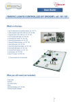
LIFT CONTROLLED BY GROOMY, ref. 182 076
What’s in the box:
1 motor,
Gear and toothed rack,
2 Groomy® switch, ref. 181 120,
3 Groomy® push button, ref. 181 126,
1 Groomy® motor controller, ref. 181 139,
2 Groomy® reed switch, ref. 181 121,
1 sets of Groomy® leads, ref. 283 124,
1 set of lead markers, ref. 315 348,
1 lift model.
What you will need (not included):
Double-sided tape, ref. 183 466,
Groomy® interface, ref. 181 000,
Groomy® SysML software.
1
The motor, the 2 Groomy® switches, the 2 Groomy® reed switches and the 3 Groomy® push buttons are
already installed onto the model, as shown below.
2 limit switches (Up / Down)
Motor
3 push buttons
2 reed switches
2
Sensors / Actuators assignment on Groomy® interface:
8 digital outputs from 1 to 8
2 analog inputs from 1 to 2
4 relay outputs
8 digital inputs from 1 to 8
4 analog inputs from 1 to 4
Thanks to foolproof Groomy® leads, connect sensors / actuators to the interface as below:
Digital inputs
3 push buttons, ref. 181 126,
Digital inputs 1, 2, 3.
2 reed switches, ref. 181 121,
Digital inputs 4, 5.
2 switches, ref. 181 120,
Digital inputs 6, 7.
3
Relay outputs
Down
Up
Connection to the motor
4


