1
CADConvert pro M4
The Mapping File
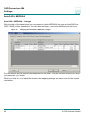
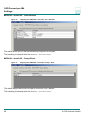
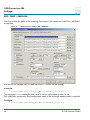
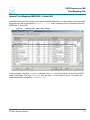
Line Mapping MEDUSA -> AutoCAD
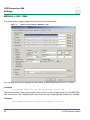
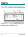
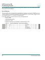
Considering as example the assignment of a MEDUSA element should be explained according
to the mapping table shown before.
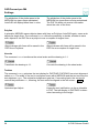
The MEDUSA element is a line of style SOLID_THIN, which is set on layer 11.
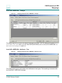
CADConvert pro starts scanning through the mapping table and searching for the entry
SOLID_THIN in the first line.
The corresponding line style is found in the first row of the mapping table, i.e. it is equal to the
input element.
Next, it is searched for layer 11.
In the first line the mapping table displays no entry, i.e. there is no setting, which means: match.
The same applies to Color and Bold.
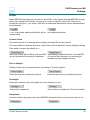
For the output, it means, since the field is blank, there is no setting for a layer. At first a default
value will be inserted here. The element obtains color 2 and type CONTINOUS.
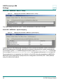
CADConvert pro continuous and searches for match to the input element in the next line.
The first cell is blank, meaning that it matches.
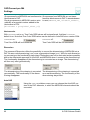
In the second cell 1018 is set as layer. However, the input element is set on layer 11, meaning
no match.
At this point CADConvert pro aborts and jumps to the next line.
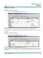
Line type SOLID_THIN matches. Layer 11 matches. Color and Bold are matching, since
there are no settings.
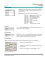
As next, layer OUTLINE is defined on AutoCAD side. With it, all fields of the output have been
defined and CADConvert pro completes searching.
In this example the MEDUSA element becomes a DXF/DWG-element of type CONTINOUS,
with Color 2 and it is set on Layer OUTLINE.
© CAD Schroer GmbH
69