1
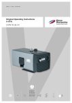
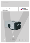
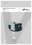
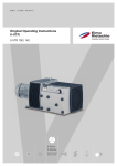
Edition: 1.12.2009 · BA 750-EN Original Operating Instructions F-RER / F-REL F-RER / REL 260 20 - F-RER / REL 620 50 F-Serie F-Series Radial Radial Table of contents Table of contents 1 Foreword . . . . . . . . . . . . . . . . . . . . . . . . . . . . . . . . . . . . . . . . . . . . . . . . . . . . . . . . . . . . . . . . . . . 4 1.1 1.2 1.3 1.4 1.5 1.6 1.7 1.8 Principles . . . . . . . . . . . . . . . . . . . . . . . . . . . . . . . . . . . . . . . . . . . . . . . . . . . . . . . . . . . . . . . . . . . Target group . . . . . . . . . . . . . . . . . . . . . . . . . . . . . . . . . . . . . . . . . . . . . . . . . . . . . . . . . . . . . . . . . Supplier documentation and accompanying documents . . . . . . . . . . . . . . . . . . . . . . . . . . . . . . Abbreviations . . . . . . . . . . . . . . . . . . . . . . . . . . . . . . . . . . . . . . . . . . . . . . . . . . . . . . . . . . . . . . . . Directives, standards, laws . . . . . . . . . . . . . . . . . . . . . . . . . . . . . . . . . . . . . . . . . . . . . . . . . . . . . Symbols and meaning . . . . . . . . . . . . . . . . . . . . . . . . . . . . . . . . . . . . . . . . . . . . . . . . . . . . . . . . . Technical terms and meaning . . . . . . . . . . . . . . . . . . . . . . . . . . . . . . . . . . . . . . . . . . . . . . . . . . . Copyright . . . . . . . . . . . . . . . . . . . . . . . . . . . . . . . . . . . . . . . . . . . . . . . . . . . . . . . . . . . . . . . . . . . 4 4 4 4 4 5 5 5 2 Safety . . . . . . . . . . . . . . . . . . . . . . . . . . . . . . . . . . . . . . . . . . . . . . . . . . . . . . . . . . . . . . . . . . . . . 6 2.1 2.2 2.3 2.4 2.5 2.6 2.7 2.8 2.9 Warning instruction markings . . . . . . . . . . . . . . . . . . . . . . . . . . . . . . . . . . . . . . . . . . . . . . . . . . . General . . . . . . . . . . . . . . . . . . . . . . . . . . . . . . . . . . . . . . . . . . . . . . . . . . . . . . . . . . . . . . . . . . . . . Designated use . . . . . . . . . . . . . . . . . . . . . . . . . . . . . . . . . . . . . . . . . . . . . . . . . . . . . . . . . . . . . . Unacceptable operating modes. . . . . . . . . . . . . . . . . . . . . . . . . . . . . . . . . . . . . . . . . . . . . . . . . . Personal qualifications and training . . . . . . . . . . . . . . . . . . . . . . . . . . . . . . . . . . . . . . . . . . . . . . . Safety-conscious work . . . . . . . . . . . . . . . . . . . . . . . . . . . . . . . . . . . . . . . . . . . . . . . . . . . . . . . . Safety notes for the operator . . . . . . . . . . . . . . . . . . . . . . . . . . . . . . . . . . . . . . . . . . . . . . . . . . . . Safety instructions for installing, commissioning and maintenance . . . . . . . . . . . . . . . . . . . . . . Guarantee conditions . . . . . . . . . . . . . . . . . . . . . . . . . . . . . . . . . . . . . . . . . . . . . . . . . . . . . . . . . . 6 6 7 7 8 8 8 9 9 3 Transport, storage and disposal . . . . . . . . . . . . . . . . . . . . . . . . . . . . . . . . . . . . . . . . . . . . . . . . 10 3.1 3.3 Transportation . . . . . . . . . . . . . . . . . . . . . . . . . . . . . . . . . . . . . . . . . . . . . . . . . . . . . . . . . . . . . . . 3.1.1 Unpack and check the delivery condition . . . . . . . . . . . . . . . . . . . . . . . . . . . . . . . . . . 3.1.2 Lifting and transporting. . . . . . . . . . . . . . . . . . . . . . . . . . . . . . . . . . . . . . . . . . . . . . . . . Storage. . . . . . . . . . . . . . . . . . . . . . . . . . . . . . . . . . . . . . . . . . . . . . . . . . . . . . . . . . . . . . . . . . . . . 3.2.1 Ambient conditions for storage . . . . . . . . . . . . . . . . . . . . . . . . . . . . . . . . . . . . . . . . . . Disposal . . . . . . . . . . . . . . . . . . . . . . . . . . . . . . . . . . . . . . . . . . . . . . . . . . . . . . . . . . . . . . . . . . . . 10 10 10 11 11 11 4 Set up and operation . . . . . . . . . . . . . . . . . . . . . . . . . . . . . . . . . . . . . . . . . . . . . . . . . . . . . . . . . 12 4.1 4.2 4.3 Setup . . . . . . . . . . . . . . . . . . . . . . . . . . . . . . . . . . . . . . . . . . . . . . . . . . . . . . . . . . . . . . . . . . . . . . 4.1.1 Data plate . . . . . . . . . . . . . . . . . . . . . . . . . . . . . . . . . . . . . . . . . . . . . . . . . . . . . . . . . . . Description . . . . . . . . . . . . . . . . . . . . . . . . . . . . . . . . . . . . . . . . . . . . . . . . . . . . . . . . . . . . . . . . . . Areas of application . . . . . . . . . . . . . . . . . . . . . . . . . . . . . . . . . . . . . . . . . . . . . . . . . . . . . . . . . . . 12 13 13 13 5 Installation . . . . . . . . . . . . . . . . . . . . . . . . . . . . . . . . . . . . . . . . . . . . . . . . . . . . . . . . . . . . . . . . . 14 5.1 5.2 5.3 5.4 Preparing for installation . . . . . . . . . . . . . . . . . . . . . . . . . . . . . . . . . . . . . . . . . . . . . . . . . . . . . . . Installation . . . . . . . . . . . . . . . . . . . . . . . . . . . . . . . . . . . . . . . . . . . . . . . . . . . . . . . . . . . . . . . . . . 5.2.1 Connection positions . . . . . . . . . . . . . . . . . . . . . . . . . . . . . . . . . . . . . . . . . . . . . . . . . . Connecting pipes . . . . . . . . . . . . . . . . . . . . . . . . . . . . . . . . . . . . . . . . . . . . . . . . . . . . . . . . . . . . . Connecting the motor . . . . . . . . . . . . . . . . . . . . . . . . . . . . . . . . . . . . . . . . . . . . . . . . . . . . . . . . . 14 14 15 15 16 6 Commissioning and decommissioning . . . . . . . . . . . . . . . . . . . . . . . . . . . . . . . . . . . . . . . . . . 17 6.1 Commissioning . . . . . . . . . . . . . . . . . . . . . . . . . . . . . . . . . . . . . . . . . . . . . . . . . . . . . . . . . . . . . . 6.1.1 Checking the rotation direction. . . . . . . . . . . . . . . . . . . . . . . . . . . . . . . . . . . . . . . . . . . Adjusting the capacity of RER/REL . . . . . . . . . . . . . . . . . . . . . . . . . . . . . . . . . . . . . . . . . . . . . . . Decommissioning/ storing . . . . . . . . . . . . . . . . . . . . . . . . . . . . . . . . . . . . . . . . . . . . . . . . . . . . . . Re-commissioning . . . . . . . . . . . . . . . . . . . . . . . . . . . . . . . . . . . . . . . . . . . . . . . . . . . . . . . . . . . . 17 17 18 19 19 3.2 6.2 6.3 6.4 2 | www.gd-elmorietschle.com © Gardner Denver Schopfheim GmbH, Gardner Denver Deutschland GmbH Table of contents 7 Maintenance and repair . . . . . . . . . . . . . . . . . . . . . . . . . . . . . . . . . . . . . . . . . . . . . . . . . . . . . . . 20 7.1 7.2 7.3 7.4 Ensuring operational safety . . . . . . . . . . . . . . . . . . . . . . . . . . . . . . . . . . . . . . . . . . . . . . . . . . . . . Maintenance work . . . . . . . . . . . . . . . . . . . . . . . . . . . . . . . . . . . . . . . . . . . . . . . . . . . . . . . . . . . . Repair/ Service . . . . . . . . . . . . . . . . . . . . . . . . . . . . . . . . . . . . . . . . . . . . . . . . . . . . . . . . . . . . . . . Spare parts. . . . . . . . . . . . . . . . . . . . . . . . . . . . . . . . . . . . . . . . . . . . . . . . . . . . . . . . . . . . . . . . . . 20 20 21 22 8 Malfunctions: Causes and elimination . . . . . . . . . . . . . . . . . . . . . . . . . . . . . . . . . . . . . . . . . . . 23 9 Technical Data . . . . . . . . . . . . . . . . . . . . . . . . . . . . . . . . . . . . . . . . . . . . . . . . . . . . . . . . . . . . . . 24 | 3 www.gd-elmorietschle.com © Gardner Denver Schopfheim GmbH, Gardner Denver Deutschland GmbH Foreword 1 Foreword 1.1 Principles These operating instructions: 1.2 • are a part of the following radial blower models F-RER / REL 260 20 to F-RER / REL 620 50. • describe how to use them safely and properly in all life phases. • must be available where the equipment is used. Target group The target group for these instructions is technically trained specialists. 1.3 Supplier documentation and accompanying documents Document Contents No. Operating Instructions BA 750-EN Declaration of Conformit C 0077-EN Declaration of harmlessness 7.7025.003.17 Spare parts’ list Spare parts’ document E 750, E 751 Data sheet Technical data and graphs D 750 - D 753, D 760 - D 763 Manufacturer’s declaration EU Directive 2002/95/EG (RoHS) — Supplier documentation 1.4 Abbreviations Fig. Figure F-RER / REL Radial blower 1.5 m3/min Volume flow, capacity mbar Pressure difference, static Directives, standards, laws See Conformity Declaration 4 | www.gd-elmorietschle.com © Gardner Denver Schopfheim GmbH, Gardner Denver Deutschland GmbH Foreword 1.6 Symbols and meaning Symbol Explanation Condition, pre-requisite #### a), b),... Instructions, action Instructions in several steps Results [-> 14] Cross reference with page number Information, note Safety symbol Warns of potential risk of injury Obey all the safety instructions with this symbol in order to avoid injury and death. 1.7 Technical terms and meaning Term Explanation Machine Blower and motor combination ready to be connected Motor Blower drive motor Radial blower Machine for both suction and pressure mode, high volume flow at small differential pressures Radial Machine’s design or active principle Volume flow The volume flow names how much air or gas volume is conveyed per time unit of a blower or streams through a pipeline Pressure difference Noise emission 1.8 Pressure difference in opposite to the atmospheric pressure at 1 bar (abs.) and 20°C The noise emitted at a specific loading given as a figure, sound pressure level dB(A) as per EN ISO 3744. Copyright Passing on or copying this document, using and providing information on its contents are prohibited unless expressly permitted. www.gd-elmorietschle.com © Gardner Denver Schopfheim GmbH, Gardner Denver Deutschland GmbH | 5 Safety 2 Safety The manufacturer is not responsible for damage if you do not follow all of this documentation. 2.1 Warning instruction markings Warning Danger level Consequences if not obeyed DANGER immediately imminent danger Death, severe bodily injury WARNING possible imminent danger Death, severe bodily injury CAUTION possible hazardous situation Slight bodily injury possible hazardous situation Material damage NOTICE 2.2 General These operating instructions contain basic instructions for installation, commissioning, maintenance and inspection work which must be obeyed to ensure the safe operation of the machine and prevent physical and material damage. The safety instructions in all sections must be taken into consideration. The operating instructions must be read by the responsible technical personnel/ operator before installing and commissioning and must be fully understood. The contents of the operating instructions must always be available on site for the technical personnel / operator. Instructions fixed directly onto the machine must be obeyed and must always remain legible. This applies for example to: • Symbols for connections • Data and motor data plate • Instruction and warning plates The operator is responsible for observing local regulations. 6 | www.gd-elmorietschle.com © Gardner Denver Schopfheim GmbH, Gardner Denver Deutschland GmbH Safety 2.3 Designated use The machine must only be operated in such areas as are described in the operating instructions: 2.4 • only operate the machine in a technically perfect condition • do not operate the machine when it is only partially assembled • the machine must only be operated at an ambient temperature of between 5 and 40°C, the temperatures of the media handled may not exceed 60°C Please contact us for temperatures outside this range. • the machine may convey, compress or extract the following media: • convey air with a relative humidity up to 90% • all non-explosive, non-inflammable, non-aggressive and non-poisonous dry gases and gas air mixtures • the machine must only be operated under a throttled condition to avoid motor overload, when not connected to a system the machine should not be used • extracting, conveying and compressing explosive, inflammable, aggressive or poisonous media, e.g. dust as per ATEX zone 20-22, solvents as well as gaseous oxygen and other oxidants, water vapour, traces of oil, liquids or solid materials • using the machine in non-commercial plants if the necessary precautions and protective measures have not been taken in the plant • installing in environments that are at risk of explosions • using the machine in areas with ionising radiation • modifications to the machine and accessories Unacceptable operating modes www.gd-elmorietschle.com © Gardner Denver Schopfheim GmbH, Gardner Denver Deutschland GmbH | 7 Safety 2.5 Personal qualifications and training • Ensure that people entrusted with working on the machine have read and understood these operating instructions before starting work, particularly the safety instructions for installation, commissioning, maintenance and inspection work. • Manage the responsibilities, competence and monitoring of staff • all work must only be carried out be technical specialists: • Installation, commissioning, maintenance and inspection work • Working with electricity • 2.6 personnel being trained to work on the machine must be supervised by technical specialists only Safety-conscious work The following safety regulations apply in addition to the safety instructions and intended use listed in these instructions: 2.7 8 • Accident prevention regulations, safety and operating regulations • the standards and laws in force • hot parts of the machine must not be accessible during operation or must be fitted with a guard • eople must not be endangered by the free extraction or discharge of pumped media • Risks arising from electrical energy must be eliminated. Safety notes for the operator | www.gd-elmorietschle.com © Gardner Denver Schopfheim GmbH, Gardner Denver Deutschland GmbH Safety 2.8 2.9 Safety instructions for installing, commissioning and maintenance • The operator will ensure that any installation, commissioning and maintenance work is carried out by authorised, qualified specialists who have gained sufficient information by an in-depth study of the operating instructions. • Only work on the machine when it is idle and cannot be switched on again • Ensure that you follow the procedure for decommissioning the machine described in the operating instructions. • Fit or start up safety and protective devices again immediately after finishing work. Vor Wiederinbetriebnahme die aufgeführten Punkte für die Inbetriebnahme beachten • Conversion work or modifications to the machine are only permissible with the manufacturer’s consent. • Only use original parts or parts approved by the manufacturer. The use of other parts may invalidate liability for any consequences arising. • Keep unauthorised people away from the machine Guarantee conditions The manufacturer’s guarantee or warranty will no longer apply in the following cases: • Improper use • Not complying with these instructions • Operation by insufficiently qualified staff • Using spare parts that have not been approved by Gardner Denver Schopfheim GmbH • Unauthorised modifications to the machine or the accessories supplied by Gardner Denver Schopfheim GmbH www.gd-elmorietschle.com © Gardner Denver Schopfheim GmbH, Gardner Denver Deutschland GmbH | 9 Transport, storage and disposal 3 Transport, storage and disposal 3.1 Transportation 3.1.1 Unpack and check the delivery condition a) Unpack the machine on receipt and check for transport damage. b) Notify the manufacturer of transport damage immediately c) Dispose of the packaging in accordance with the local regulations in force. 3.1.2 Lifting and transporting WARNING Death or limbs crushed as a result of the items being transported falling or tipping over. a) b) c) d) When transporting with the lifting device remember: Select the lifting device suitable for the total weight to be transported. Ensure that the machine cannot tip and fall. Do not stop under a suspended load. Put the goods to be conveyed on a horizontal base. Lifting device/ Transporting with a crane WARNING 1 Bodily injury resulting from improper operation a) Loads crosswise to the ring level are not permitted. b) Avoid impact stress. a) Tighten the eyebolts (Fig. 1/1) firmly. b) The machine must be suspended on the eyebolt using the lifting device for lifting and transporting. Fig. 1 Lifting and transporting 1 10 Eyebolt | www.gd-elmorietschle.com © Gardner Denver Schopfheim GmbH, Gardner Denver Deutschland GmbH Transport, storage and disposal 3.2 Storage NOTICE Material damage caused by improper storage. Ensure that the storage area meets the following conditions: a) dust free b) vibration free 3.2.1 Ambient conditions for storage Ambient conditions Value Relative humidity 0% to 80% Lagertemperatur -10°C to +60°C The machine must be stored in a dry environment with normal air humidity. It should not be stored for more than 6 months. 3.3 Disposal WARNING Danger from inflammable, corrosive or poisonous substances. Machines that come into contact with hazardous substances must be decontaminated before disposal. a) b) c) d) e) When disposing ensure the following:: Collect oils and grease separately and dispose of in accordance with the local regulations in force. Do not mix solvents, limescale removers and paint residues Remove components and dispose of them in accordance with the local regulations in force. Dispose of the machine in accordance with the national and local regulations in force. Parts subject to wear and tear (marked as such in the spare parts list) are special waste and must be disposed of in accordance with the national and local waste laws. www.gd-elmorietschle.com © Gardner Denver Schopfheim GmbH, Gardner Denver Deutschland GmbH | 11 Set up and operation 4 Set up and operation 4.1 Setup F-RER (01) F-RER (70) d A A F-RER (40) B1 B1 A1 B f N F-RER O N F-REL F O F E E F F h h Fig. 2 Radial blower F-RER (Clockwise rotation) / F-REL (Counter-clockwise rotation) A Vacuum connection N Data plate A1 Suction O Direction of rotation B Pressure connection d Hose connection B1 Exhaust air connection h Motor cover E Cooling air entry f Mesh F Cooling air exit 12 | www.gd-elmorietschle.com © Gardner Denver Schopfheim GmbH, Gardner Denver Deutschland GmbH Set up and operation 4.1.1 Data plate 1 2 3 5 4 Bauj./Nr. 09 6 3~ Mot. 2862646 Typ RER 32040 (01) 1016870154 pmax. + 19,5 mbar max. 990 m³/h Y Δ/ 230/400 V ± 10% 2,15/1,25 A 50 Hz EN 60034 S1 2830 min-1 0,55 kW 13 12 11 Fig. 3 Data plate 4.2 10 9 8 7 1 Type/ Size (mechanical version) 2 Year of construction 3 Serial number 4 Motor design 5 Item no. 6 Pressure difference, static 7 Frequency 8 Capacity 9 Current drawn 10 Speed 11 Voltage 12 Motor rating 13 Operating mode Description The radial blowers F-RER and F-REL work according to the dynamic compressing principle utilising a non contact rotating impellor. They are free of maintenance. They have a built-in motor. A high efficiency impellor is fitted on to the motorshaft. A shaft seal is fitted between the bearing and pumping chamber. The motor fan cools both the motor and blower housing. Models F-RER rotate to the right, whilst the models F-REL rotate to the left. The models F-RER and F-REL can be delivered with different suction connections: Version (01) to (39) with connection flange, version (40) to (69) with mesh flange and version (70) to (99) with pipe socket. 4.3 Areas of application The models F-RER and F-REL can be operated as vacuum pumps or compressors. They have capacities from 4.9 to 57 m3/min and obtain a pressure difference of up to 74 mbar on 50 cycle operation. The pressure and vacuum limits are indicated on the data plate (Fig. 2/N). The performance curves showing capacity against vacuum or pressure can be seen in data sheets D 750, D 751, D 752 and D 753 or D 760, D 761, D 762 and D 763. The maximum permissible capacity for air depends upon the motor rating. This is indicated on the data plate (N) and is shown in the data sheets for standard voltages and frequencies. The loading of each unit depends on the specific gravity of the gas handled. Therefore when handling gases other than air there are other pressure different limits to be considered. Please contact the supplier for further advice. If the unit is switched on more frequently (at regular intervals of about 10 times per hour or at higher ambient temperatures and intake temperatures, the excess temperature limit of the motor winding and the bearings may be exceeded.Please contact the manufacturer should the unit be used under such conditions. If it is installed in the open air the unit must be protected from environmental influences, (e.g. by a protective roof). www.gd-elmorietschle.com © Gardner Denver Schopfheim GmbH, Gardner Denver Deutschland GmbH | 13 Installation 5 Installation 5.1 Preparing for installation Check the following points: • • Machine freely accessible from all sides Do not close ventilation grids and holes • Sufficient room for installing and removing pipes and for maintenance work, particularly for installing and dismantling the machine • No external vibration effects • Do not suck any hot exhaust air from other machines into the cooling system. The cooling air inlets (Fig. 2/E) and the cooling air outlets (Fig. 2/F) must be at least 20 cm away from adjacent walls. Cooling air coming out must not be sucked in again. Additionally care should be taken that the suction air entry (Fig. 2/A1) and the exhaust air exit (Fig. 2/B1) are not obscured. 5.2 Installation NOTICE The machine may only be operated when it is set up horizontally. Material damage resulting from the machine tipping over and falling. When installed at more than 1000 m above sea level a reduction in power is noticeable. In this case we would ask you to contact us. Ensure that the foundation complies with the following conditions: • Even and level • The bearing surface must be designed to be able to take the weight of the machine It is possible to install the machine on a firm base without anchoring. When installing on a substructure we recommend fixing with flexible buffers. 14 | www.gd-elmorietschle.com © Gardner Denver Schopfheim GmbH, Gardner Denver Deutschland GmbH Installation 5.2.1 Connection positions The radial blowers F-RER and F-REL can be operated in 4 different connection positions. Standard version is position 01. F-RER 01 02 03 02 03 04 F-REL 01 04 Fig. 4 Connection positions 5.3 Connecting pipes a) When on vacuum operation connect the suction pipe at (Fig. 2/A) and when on pressure operation connect the pressure pipe at (Fig. 2/B). NOTICE Long and/or small bore pipework should be avoided as this tends to reduce the capacity of the blower. Radial blowers must only be operated under a throttled condition to avoid motor overload. The units should not be used when not connected to a system. b) Check to ensure the intake line and pressure connection are connected correctly. www.gd-elmorietschle.com © Gardner Denver Schopfheim GmbH, Gardner Denver Deutschland GmbH | 15 Installation 5.4 Connecting the motor DANGER Danger of death if the electrical installation has not been done professionally. The electrical installation must only be done by a qualified electrician observing EN 60204. The operating company has to provide the main switch. a) The motor‘s electrical data is given on the data plate (Fig. 2/N) or on the motor data plate. The motors comply with DIN EN 60034 and are in protection class IP 55 and insulation class F. The appropriate connection diagram is located in the motor‘s terminal box (not for the plug connection version). The motor data must be compared with the data of the existing mains network (current type, voltage, network frequency, permitted current value). b) Connect the motor via the plug connection or a motor protection switch (for safety reasons a motor protection switch is required and cable fitting must be provided to provide strain relief for the connection cable). We recommend using motor protection switches with delayed switch off, depending on possible excess current. Temporary excess current may occur when the machine is started cold. NOTICE Power supply The conditions at the installation location must match the information on the motor data plate. Without derating the following is permissible: • ± 5% Voltage deviation • ± 2% Frequency deviation 16 | www.gd-elmorietschle.com © Gardner Denver Schopfheim GmbH, Gardner Denver Deutschland GmbH Commissioning and decommissioning 6 Commissioning and decommissioning 6.1 Commissioning WARNING Improper use May lead to severe or fatal injuries. Therefore be sure to obey the safety instructions. CAUTION Noise emission The highest noise pressure levels measured as per EN ISO 3744 are given in Section 9. When spending a long time in the vicinity of the running machine use ear protectors to avoid permanent damage to your hearing. 6.1.1 Checking the rotation direction The intended direction of rotation of the drive shaft is shown by the rotary direction arrow (Fig. 2/O) on the motor cover (Fig. 2/h). a) Start the motor briefly (max. two seconds) to check the direction of rotation. The direction of rotation can be seen by looking through the slots of the motor fan cover. When looking at the motor fan, it must rotate at F-RER clockwise and at F-REL anti-clockwise. NOTICE Incorrect direction of rotation Running in reverse for a long time may damage the machine. Use a phase sequence indicator to check the direction of rotation (F-RER ➝ anti-clockwise rotating field, F-REL ➝ clockwise rotating field). www.gd-elmorietschle.com © Gardner Denver Schopfheim GmbH, Gardner Denver Deutschland GmbH | 17 Commissioning and decommissioning 6.2 Adjusting the capacity of RER/REL To avoid overloading the motor during starting please take note of the following: a) Do not start the radial blower unless it is connected on the pressure or suction side. b) If the air requirement of the system is variable e.g. through valves, taps or variables inlet and/or outlet orifices then these should be set so that maximum capacity is utilised. During start up this condition will result in the highest motor load. c) The full load current as indicated on the nameplate of the blower motor determines the maximum available capacity of the blower. When starting up the blower please check: I) Whether the voltage and the frequency correspond to the data on the data plate? II) Whether at peak load the full load current is exceeded? d) Exceeding the full load current indicates (if the voltage and frequency are correct) that the blower has been overloaded with regard to capacity. In such a case the power should be adjusted by throttling. Throttling can be achieved without changing the base unit itself as follows: d.1) Insert a ring shaped orifice plate made of aluminium or steel between the connection flange of the blower and the pipe or at any place in the pipe. Its outside diameter and fixing holes should conform with the size of the flange. However its inside diameter should be smaller than the effective diameter of the flange. Adjust the internal diameter so that the amperage does not exceed the full load current. Or: d.2) Insert an adjustable valve i.e. ball or butterfly between the connection flange of the blower and the pipe or at any place in the pipe and adjust it so that the running amps do not exceed the full load current. It is advisable to clamp the valve in this position so that the setting cannot be altered unless by authorised personnel. The points d.1 and d.2 can be omitted if it is possible to reduce the power to the design value by reducing the suction and/or exhaust diameter or by increasing the flow resistance within the system. e) 18 Instead of adjusting the system to the existing blower, it is possible depending on the model of blower and on the rating of the motor to use the same size blower but with a larger motor. For further advice please contact your Rietschle representative. | www.gd-elmorietschle.com © Gardner Denver Schopfheim GmbH, Gardner Denver Deutschland GmbH Commissioning and decommissioning 6.3 Decommissioning/ storing Stop the machine a) Switch the machine off. b) If available close the cut off device in the suction and pressure pipe. c) Disconnect the machine from the electricity source. d) Depressurise the machine: Open the pipes slowly. The pressure reduces slowly. e) Remove the pipes and hoses. f) Seal the connections for suction and pressure nozzles using adhesive foil. see also Section 3.2.1, Page 11 6.4 Re-commissioning a) Check the condition of the machine (cleanliness, cabling etc.). For installation see Section 5 Page 14 For commissioning see Section 6.1 Page 17 www.gd-elmorietschle.com © Gardner Denver Schopfheim GmbH, Gardner Denver Deutschland GmbH | 19 Maintenance and repair 7 Maintenance and repair DANGER Danger of death from touching live parts. Before maintenance work disconnect the machine by pressing the main switch or unplugging it and ensure that it cannot be turned on again. NOTICE Capacitor In case of capacitor failure (1 ~ drive) replace the capacitor only with one that has identical rated value. 7.1 Ensuring operational safety Regular maintenance work must be carried out in order to ensure operational safety. Maintenance intervals also depend on the operational demands on the machine. With any work observe the safety instructions described in Section 2.8 “Safety notes for installation, commissioning and maintenance”. The whole unit should always be kept in a clean condition. 7.2 Maintenance work Interval Maintenance to be carried out Section monthly Check the pipes and screws for leaks and to ensure they are seated properly and if necessary seal again or tighten up. — monthly Check the terminal box and cable inlet holes for leaks and if necessary re-seal. — monthly Clean the ventilation slots on the machine and the motor cooling ribs. — depending on how dirty the discharged medium is To make sure that full capacity is always obtained check the mesh (Fig. 2/f) and clean if required. — 20 | www.gd-elmorietschle.com © Gardner Denver Schopfheim GmbH, Gardner Denver Deutschland GmbH Maintenance and repair 7.3 Repair/ Service a) For on site repair work the motor must be disconnected from the mains by a qualified electrician so that it cannot be started up again accidentally. For repairs use the manufacturer, its branch offices or authorised dealers. Please contact the manufacturer for the address of the service centre responsible for you (see Manufacturer‘s address). NOTICE For each machine that is sent to an Elmo Rietschle Service centre for inspection, maintenance or repair, a fully completed, signed declaration of harmlessness must be enclosed. The declaration of harmlessness is part of the supplier‘s documentation. b) After a repair or re-commissioning, the actions listed under „Installation“ and „Commissioning“ must be carried out as for initial commissioning. Fig. 5 Clearance certificate 7.7025.003.17 www.gd-elmorietschle.com © Gardner Denver Schopfheim GmbH, Gardner Denver Deutschland GmbH | 21 Maintenance and repair 7.4 Spare parts Order spare parts in accordance with the: • Spare parts list: E 750 ➝ F-RER 260 20 - F-RER 620 50 E 751 ➝ F-REL 260 20 - F-REL 620 50 • Download the PDF file http://www.gd-elmorietschle.com ➝ Downloads ➝ Product Documents ➝ F-Series ➝ Spare Parts • Parts subject to wear and gaskets are indicated separately on the list. • Web site: http://www.service-er.de • Select the type, size and design. NOTICE Fig. 6 Spare parts list (example) Fig. 7 22 Only use original spare parts or parts approved by the manufacturer. The use of other parts may lead to malfunctions and invalidate liability or the guarantee for any consequences arising. Web site http://www.service-er.de | www.gd-elmorietschle.com © Gardner Denver Schopfheim GmbH, Gardner Denver Deutschland GmbH Malfunctions: Causes and elimination 8 Malfunctions: Causes and elimination Fault Cause Troubleshooting Important Machine is switched off by the motor protection switch Mains voltage/ Frequency does not correspond with the motor data Check by qualified electrician Section 5.5 Connection to motor terminal board is not correct Motor protection switch is not set correctly Insufficient suction or pressure capacity Machine gets too hot Motor protection switch is triggered too quickly Use a motor protection switch with an overload-dependent delayed switch off that takes into consideration the short term excess current at start up (version with short circuit and overload trigger as per VDE 0660 Part 2 orIEC 947-4) Blower operates without connection to a system Connect system Motor rating selected was too small If available use a blower with the next Data sheets motor size (exchange of the motor only D 750 - D 753 is not possible) D 760 - D 763 Motor rating selected was too small If available use a blower with the next Data sheets motor size (exchange of the motor only D 750 - D 753 is not possible) D 760 - D 763 Lines are too long or too narrow Check the hose or the pipe Section 5.3 Machine or system leaking Check the pipework and screw connections for leaks and to ensure that they are firmly seated Section 7.2 Ambient or intake temperature is too high Ensure it is being used properly Section 2.3 Blower sucks too little air Check the rotation direction resp. cross Section 6.1.1 sections of the pipes Section 5.3 Cooling air supply is obstructed Check environmental conditions Section 5.1 Clean ventilation slots Section 7.2 Use an additional silencer ZSD (optional extra) Data sheets Z 926, Z 927 Unacceptable Exhaust noise when used as noise a vacuum pump or inlet noise when used as a compressor Section 5.3 Section 6.2 Please contact Elmo Rietschle Service for other malfunctions or those that cannot be eliminated. www.gd-elmorietschle.com © Gardner Denver Schopfheim GmbH, Gardner Denver Deutschland GmbH | 23 Technical Data 9 Technical Data F-RER / F-REL Sound pressure level (max.) EN ISO 3744 Tolerance± 3 dB(A) Weight * 260 20 260 50 320 10 320 20 320 40 350 20 50 Hz 72 78 74 76 78 78 60 Hz 73 79 75 77 79 79 3~ 15 22 22 22 30 30 1~ 18 - 20 21 - 35 dB(A) kg Length * mm 292 324 292 306 344 323 Width mm 352 373 413 421 438 467 Height mm 409 450 476 480 517 533 320 50 350 30 350 50 400 20 400 50 440 20 50 Hz 82 80 84 80 87 82 60 Hz 83 81 86 81 89 83 50 Hz 94 91 94 91 96 94 60 Hz 95 92 96 92 98 95 F-RER / F-REL Sound pressure level (max.) EN ISO 3744 Tolerance± 3 dB(A) dB(A) Sound power level dB(A) Weight * kg 33 30 36 38 57 43 Length * mm 394 342 407 392 478 392 Width mm 451 467 486 530 566 607 Height mm 523 533 587 610 672 686 440 50 530 20 530 50 620 10 620 50 50 Hz 87 84 88 89 90 60 Hz 89 86 90 90 92 50 Hz 97 95 99 98 101 60 Hz 99 97 101 99 103 F-RER / F-REL Sound pressure level (max.) EN ISO 3744 Tolerance± 3 dB(A) dB(A) Sound power level dB(A) Weight * kg 65 62 72 75 115 Length * mm 505 460 504 448 582 Width mm 631 671 691 769 817 Height mm 720 765 775 862 960 * The length and the weight may differ from the information listed here depending on the motor manufacturer. 24 | www.gd-elmorietschle.com © Gardner Denver Schopfheim GmbH, Gardner Denver Deutschland GmbH Technical Data You will find more technical data on the data sheets D 750 - D 753 and D 760 - D 763 • Fig. 8 Data sheet (example) Download the pdf file: Vacuum version: D 750 ➝ F-RER / REL 260 20, F-RER / REL 260 50 F-RER / REL 320 10, F-RER / REL 320 20 F-RER / REL 320 40, F-RER / REL 350 20 F-RER / REL 350 30 D 752 ➝ F-RER / REL 320 50, F-RER / REL 400 20 F-RER / REL 440 20, F-RER / REL 620 10 D 753 ➝ F-RER / REL 350 50, F-RER / REL 400 50 F-RER / REL 440 50, F-RER / REL 530 20 F-RER / REL 530 50, F-RER / REL 620 50 Pressure version: D 760 ➝ F-RER / REL 260 20, F-RER / REL 260 50 F-RER / REL 320 10, F-RER / REL 320 20 F-RER / REL 320 40, F-RER / REL 350 20 F-RER / REL 350 30 D 762 ➝ F-RER / REL 320 50, F-RER / REL 400 20 F-RER / REL 440 20, F-RER / REL 620 10 D 763 ➝ F-RER / REL 350 50, F-RER / REL 400 50 F-RER / REL 440 50, F-RER / REL 530 20 F-RER / REL 530 50, F-RER / REL 620 50 • Download the pdf file: http://www.gd-elmorietschle.com ➝ Downloads ➝ Product Documents ➝ F-Series ➝ Data Sheets NOTICE Subject to technical changes. www.gd-elmorietschle.com © Gardner Denver Schopfheim GmbH, Gardner Denver Deutschland GmbH | 25 www.gd-elmorietschle.com [email protected] Gardner Denver Schopfheim GmbH Roggenbachstraße 58 79650 Schopfheim · Deutschland Tel. +49 7622 392-0 Fax +49 7622 392-300 Elmo Rietschle is a brand of Gardner Denver‘s Industrial Products Division and part of Blower Operations. EC - declaration of conformity 2006/42/EC Hereby the manufacturer confirms: Gardner Denver Schopfheim GmbH Postfach 1260 D-79642 Schopfheim that the machine: of the: Radial blower Series: F-REL / F-RER Type: F-REL 260 20, F-REL 260 50, F-REL 320 10, F-REL 320 20, F-REL 320 40, F-REL 320 50, F-REL 350 20, F-REL 350 30, F-REL 350 50, F-REL 400 10, F-REL 400 20, F-REL 400 50, F-REL 440 20, F-REL 440 50, F-REL 440 60, F-REL 470 20, F-REL 530 20, F-REL 530 50, F-REL 620 07, F-REL 620 10, F-REL 620 50 F-RER 260 20, F-RER 260 50, F-RER 320 10, F-RER 320 20, F-RER 320 30, F-RER 320 40, F-RER 320 50, F-RER 320 60, F-RER 350 20, F-RER 350 30, F-RER 350 50, F-RER 400 10, F-RER 400 20, F-RER 400 25, F-RER 400 50, F-RER 400 80, F-RER 440 20, F-RER 440 50, F-RER 440 60, F-RER 440 80, F-RER 470 20, F-RER 530 20, F-RER 530 50, F-RER 620 07, F-RER 620 10, F-RER 620 50 is conform to the regulations of the guideline indicated above. The following harmonized and national standards and specifications are applied: EN 1012-1:2010 Compressors and vacuum pumps — Safety requirements — Part 1: Compressors EN 1012-2:1996+A1:2009 Compressors and vacuum pumps — Safety requirements — Part 2: Vacuum pumps These declarations of conformity are invalid when the machine has been modified without prior approval by us and the approval has been documented in writing. Name and address of the EC person in charge for documentation Gardner Denver Schopfheim GmbH Postfach 1260 D-79642 Schopfheim Gardner Denver Schopfheim GmbH Schopfheim, 1.8.2011 Dr. Friedrich Justen, Director Engineering C_0077_EN Safety declaration form for vacuum pumps and components 7.7025.003.17 Page 1 of 1 Gardner Denver Schopfheim GmbH Roggenbachstr. 58, 79650 Schopfheim Phone: +49/(0)7622/392-0 Fax: +49/(0)7622/392-300 Repairs and/or maintenance of vacuum pumps and components will only be carried out if a declaration has been filled in correctly and completely. If not, the repair work cannot be started and delays will result. This declaration must only be filled in and signed by authorised qualified staff. 1. Type of vacuum pumps/ components 2. Reason for the submission Type description: Machine number Order number: Delivery date: 3. Condition of vacuum pumps/ components YES NO 4. Contamination of the vacuum pumps/ components when in use Toxic YES NO Corrosive YES NO Was the pump/ component emptied? Microbiological*) YES NO (Product/Consumables) YES NO Explosive*) YES NO Has the pump/ component been cleaned and decontaminaRadioactive*) YES NO other YES NO YES Was this being operated? Which lubrication was used? Cleaning agent: Cleaning method: *) Microbiological, explosive or radioactively contaminated vacuum pumps/ components will only be accepted with proof that they have been cleaned properly. Type of toxic substance or process-related, dangerous reaction products with which the vacuum pumps/ components came into contact: Trade name, manufacturer's product name 1 2 3 4 Chemical name Hazard class Action to be taken if toxic substances are released First aid in the event of accidents Personal protection measures: YES Hazardous decomposition products when subjected to thermal load NO Which? 5. Legally binding declaration We swear that the information in this declaration is accurate and complete and that I, the undersigned, am in a position to judge this. We are aware that we are liable to the contractor for damage caused by incomplete and inaccurate information. We undertake to release the contractor from any damage claims from third parties arising from incomplete or incorrect information. We are aware that, regardless of this declaration, we are directly liable to third parties including in particular the contractor's staff entrusted with handling or repairing the product. Company: Street: Post code/ Town: Phone: Fax: Name (in capitals) Date: Position: Company stamp: Legally binding signature: TOS no. / Index: 7.7025.003.17 / 03 Office responsible: GS File management: ..\7702500317.xl Gardner Denver Schopfheim GmbH Postfach 1260 D-79642 Schopfheim