1
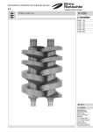
Instruction and service manual Screw vacuum pumps S-VSB S-VSB 120 S-VSB 200 S-VSB 320 S-VSB 430 S-VSB 800 S-VSB 2700 BE 831 2.1.2002 Gardner Denver Schopfheim GmbH Postfach 1260 79642 SCHOPFHEIM GERMANY Fon +49 7622 / 392 -0 Fax +49 7622 / 392 -300 e-mail: er.de@ gardnerdenver.com www.gd-elmorietschle.com Screw vacuum pumps Table of contents: Page: 1. Introduction 3 2. Application 3 3. 3.1 3.2 3.3 3.4 3.4.1 3.4.2 3.4.3 3.5 3.5.1 3.5.2 3.6 General Construction General Construction Technical specifications Cooling system Fresh water cooling Circulation Cooling Cooling gas Gases Sealing gas Cleaning gas Bleeding valve 4 4 4 4 5 5 5 5 5 5 5 5 4. 4.1 4.1.1 4.1.2 4.1.3 4.2 4.2.1 4.2.2 4.3 4.4 4.5 4.6 4.7 Handling procedure Assembly of piping Location Foundation Installation Piping work Main piping Cooling water piping Coupling drive Preparation for operation Operation Stopping Lubrication 6 6 6 6 6 6 6 6 6 6 6 6 6 5. 5.1 5.2 5.3 5.3.1 5.3.2 5.4 5.4.1 5.4.2 Maintenance and inspection General Periodical inspection Disassembly Cautions in disassembly Disassembling procedure Re-assembly Cautions in re-assembly Re-assembling procedure 7 7 7 8 8 8 8 8 9 6. Trouble shooting 10 Data sheets: D 831 / 1 ➝ VSB (30), (20) Spare parts list: E 831 / 1 ➝ VSB (01) -2- 1. Introduction To prevent contamination from possible dangerous substances contained in the process, the exhaust outlet must always be connected to an appropriate emission control system. All units being returned to our works for maintenance or any other reason must be free of harmful and dangerous material. A Health and Safety certificate should always be provided. The customer has the responsibility for providing and checking explosion proof safety requirements for the total site in which vacuum pumps are used. An appropriate agreement should be obtained from the local licensing authorities. 2. Application The TWISTER vacuum pumps are particularly suitable for the handling of extremely humid gases. These pumps have a high water vapour tolerance. The ambient temperatures may be between 5 and 40°C. The suction temperatures should not exceed 60°C. For temperatures out of this range please contact your supplier. Liquid slugs and solids cannot be handled by TWISTER. Handling of explosive gases or vapours only on request with our company. For installations that are higher than 1000 m sea level there will be a loss in capacity. For further advice please contact your supplier. The standard versions may not be used in hazardous areas. Special versions with Ex-proof motors can be supplied. All applications where an unplanned shut down of the pump could possibly cause harm to persons or installations, then the corresponding safety backup systems must be installed. Cut view TWISTER VSB � -3- 3. General Construction 3.1 General The Rietschle TWISTER pumps gases and vapours by use of two screw rotors, having a profile comprising a plurality of curves, i.e. Archimedean curve, Quimby curve and arc, which rotate smoothly with a certain clearance maintained between each other and inside wall of the casing. The gases and vapours being pumped are smoothly pressurised up to the pressure on the discharge side. The pump is so constructed as to prevent oil from entering the pumping chamber. The power of the motor is transmitted to the gear by a coupling. 3.2 Construction � • Rotor shaft: The rotor shaft is made of high grade spheroidal graphite cast steel, and precision machined through numerical control by a special machine. It is perfectly dynamically balanced after the rotor is machined. • Timing Gear: The timing gears are the most important part of the screw vacuum pump, and they are required to maintain the precision clearance between the rotors. The tooth surface is heat cured, and then polished with a special high precision tooth polishing machine for noise reduction. • Bearing: The bearings on the fixed end are angular contact ball bearings and on the floating end are roller bearings of heavy load capacity. These bearings have been selected for high speed and heavy load service and to assure the accurate maintenance of clearances between gears and between rotors. • Shaft sealing suction side: The shaft sealing consists of two double lipped shaft seals. Shaft sealing pressure side: A mechanical spring plate assures sealing between the chamber and the gear box. An additional single lipped shaft seal in combination with sealing gas prevents foreign particles from entering the sealing system. Shaft sealing gear box: A single lipped shaft seal seperates the gear box from the atmospheric pressure. • Oil Level Gauge: The Oil Level Gauge is located in the Front End Cover. Oil should be supplied to the top level of Red mark. If the oil level is too low, Gear, Bearing and Mechanical Seal will be damaged as a result of improper lubrication. The timing gears, bearings and mechanical seals are splash lubricated. Check oil level and look for contamination when the pump is stopped. 3.3 Technical specifications VSB 50 Hz Nominal (theoretical) Displacement m³/h 60 Hz Ultimate vacuum mbar (abs.) bar (abs.) Discharge pressure 50 Hz kW Motor rating 60 Hz 50 Hz min-1 Speed 60 Hz DN Port size (Suction / Discharge) l Gear oil bar (abs.) Max. internal pressure l/h Cooling water bar (abs.) Cooling water pressure Nm3/h Cooling gas cm³/min Sealing gas Front end plate Seal type Rear end plate Front end cover (drive shaft kg Weight 120 (30) 200 (30) 80 100 0,3 120 150 0,3 3,0 3,6 40 0,45 120 - 120 320 (30) 430 (30) 800 (30) 220 330 560 260 400 700 0,3 0,3 0,05 max. 1,3 4,0 5,5 7,5 15 4,8 6,5 9,0 18 2850 3450 50 / 40 50 / 40 80 / 50 100 / 80 1,0 1,6 1,8 2,0 10 240 480 660 1200 max. 6 25 30 max. 3 Bellows type mechanical seal Lip seals Oil seal 240 480 660 1200 2700 (20) 1700 2100 0,05 55 65 1450 1740 150 / 100 9,0 2160 30 2160 Note: (1) The quantity of oil listed is only for reference, and surplus should be available. It should be noted that fluorine and mineral based oils can be used. For shipping, we supply pure gear oil. (2) The Cooling Water flow quoted is based on water temperature of 20° C. The amount of water will vary when using an After Cooler. Please check with Vendor’s approved drawing. -4- 3.4 Cooling system TWISTER pumps are water cooled. They are distinguished in: 3.4.1 Fresh water cooling The fresh water cooling system is characterised by a continuous flow of the cooling water through a hollow space between the inner and outer wall of the chamber. For safety reasons the cooling system is equipped with a temperature switch and a flow switch. Cooling water inlet Cooling water outlet Flushing gas Cooling gas Flushing gas Cooling gas 3.4.2 Circulation Cooling The circulation cooling system is equipped with a radiator. Two different types of radiators can be used: Air-water radiator: A bypass piping and a 3-way valve with integrated temperature controller bypass the cooling water around the air-water. During operation of the pump a temperature switch monitors the water temperature and a flow switch supervises the water flow rate. The radiator is equipped with an integrated fan. The cooling circuit is furthermore equipped with a tap through which it is filled, an expansion tank, a relief valve and a manometer. 3.4.3 Cooling gas This purge is intended to cool the rotors and internals which are heated by gas compression.. Since this compression heat can reach above 200° C in the discharge side, a cooling purge is needed to cool the gases. In most cases, an atmospheric air cooling purge is used, this is the standard purge. An air filter is provided near the discharge side of the casing for this purge. Cooling gas capacity see table page 4. Remark: The TWISTER VSB 120 does not require any cooling gas! (1) Purge gas flow This purge gas flow can vary according to operating vacuum level (2) Type of Cooling Purge 1. Standard: Atmosphere purge through air filter 2. Using Heat Exchanger, Recycle process gases after cooling through the heat exchanger. 3. As an alternative other gases may be used. 3.5 Gases 3.5.1 Sealing gas (see picture �) The sealing gas is located on the pressure side between the mechanical spring plate and the single lipped shaft seal. It prevents process gases and liquids from entering the gear box and the bearings. The maximum gas pressure allowed is 1,5 bar (abs). The mechanical seals guarantee a sealing up to 4 bar (abs.). 3.5.2 Cleaning gas This purge is used to clean the inside the pump before stopping. Before stopping the pump, purge with N2 gas, steam or cleaning agent for 20 to 30 minutes after closing the main suction valve to clean sticky process materials or process gases. This purge is especially important when pumping corrosive/ toxic or sticky materials like resin etc. Flushing gas Cooling gas Water-water radiator: The external cooling circuit is connected to the factory’s main water supply. It is equipped with a dust trap and a temperature controlled valve. This valve remains closed during the start run of the pump. The internal cooling circuit is equipped with a temperature switch that monitors the cooling water temperature and a flow switch that regulates the water flow rate. The circuit includes furthermore a tap through which it is filled, an expansion tank, a relief valve and a manometer. 3.6 Bleeding valve The suction side of the pump is equipped with a bleeding valve which implies two functions On start run: In an hazardous environment the pump in neutralized with an inert gas. While bringing the pump to operating temperature it is flooded with inert gas. Shutting the pump down: After the process the pump is neutralized with an inert gas. -5- 4. Handling procedure 4.1 Assembly of piping 4.1.1 Location • Mount the Pump on a clean, flat & level surface of sufficient rigidity. If it is to be installed outdoors, check motor, V-belt and other parts are for outdoor service. • There should be enough space for maintenance, disassembly, reassembly and periodical inspection, etc. 4.1.2 Foundation • The pump can be mounted on a suitable concrete plinth or steel framework. 4.1.3 Installation • Mount the pump horizontally and centre it in accordance with the instruction manual. The pump should be level to within 0.5 mm per metre. 4.2 Piping Work 4.2.1 Main Piping • Clean the inside of suction and discharge pipework to ensure it is free from rust, dust and foreign matter, place a strainer of 40 mesh on or over suction port. • It is advisable to install an expansion joint on the suction and discharge side of the pumps. Provide supports for piping so that no excessive load to be imposed on the pump. • If silencer is to be fitted on the discharge side, install it as near the discharge port as possible. • Be sure to install a Non-return Valve adjacent to the suction port so that the pump will not turn in reverse when switched off. If installation of the Non-return Valve is a problem for the duty of the pump, install a shut off valve, and ensure it is closed prior to stopping the pump. • In the event of condensate being collected at the pump discharge, a collection tank may be installed under the pump, and then the condensate and water will be collected during operation and be discharged by the opening of a drain valve. • A drain receiver should be installed under the drain valve to collect discharge. 4.2.2 Cooling water piping Cooling water required to cool front end plate and casing. The piping should be assembled with reference to the piping diagram and the outline drawing supplied. * If Water Jacket type Silencer is installed, this Silencer also requires cooling water. 4.3 Coupling drive Align coupling by using Dial Gauge. The concentricity should be as follows: Motor side Pump side Motor side Pump side Feeler gauge Class of motor M180 M200M and above On side of coupling less than 0.05 less than 0.08 Class of motor M132M and under M160M and above At end of coupling less than 0.1 less than 0.18 4.4 Preparation for operation • Remove dust from Vacuum Pump and piping. Clean the pipework thoroughly, ensuring welding slag and debris etc. are removed. • Check all suction and discharge connections are properly tightened and all the piping is properly supported. Also check cooling water piping. • Supply oil up to the red mark of the oil gauge. If oil level is low, gear and bearings can seize, and if oil level is too high, the temperature will rise excessively, and can be the cause of gear noise or some effect on other parts. • Cooling water flow to be as specified in chart 1.3. 4.5 First Operation Warning –> Start-up with pipework At start-up, severe damage may occur if there is debris in the pipework. We therefore recommend a vacuum tight inlet filter of 5 micron rating is installed for start-up. • With suction valve closed, run the motor briefly to check direction of rotation, correct if required. • Run the pump under no load condition for 20-30 minutes to check for any abnormal vibration or heat. In case of any abnormality, stop the pump and search for the cause. In most cases, the cause is improper installation or coupling centring. Check for correct lubricant level. • Run the pump for 2 - 3 hours under normal load condition and check the temperature and vibration of each parts. • During operation, pay attention to indication of motor ampere Meter. If any abnormality is found, stop the pump immediately and check the cause. Often, the cause is interference between rotors or between the periphery of rotor and the inner surface of casing. All pumps are factory run before despatch, however, full care will be still necessary after the pump installed on site. * Caution during Operation: • Check temperature of bearing & lubricant and indication of Ampere meter & cooling water. • Keep operation within designated specifications. 4.6 Stopping • Shut suction valve. • If any corrosive gas, solvent or water vapour has been pumped, introduce atmospheric air ( or N2) from suction side for 20-30 minutes before stopping to clean the pump internals. If a solvent or steam cleaning purge is used, run the pump for 10 minutes on air or N2 purge only after steam/ solvent has been turned off. • Stop the pump by turning off the motor. • Shut off cooling water. If freezing is anticipated, discharge water by opening of drain valves. 4.7 Lubrication Lubricants to be used must be good and high grade petroleum products containing oxidation inhibitor, rust preventive, extreme-pressure additive, etc. (Do not use any lubricant which contains any element of water , sulphate resin or tar.). Turbine oil (ISO VG 68) readily obtainable in the market will generally satisfy these requirements. The following brands are recommended for use as lubricants for gear and bearing. • Lubricant: BP Energol THHT 68, BP Energol THB 68, Regal R & O 68, Shell Turbo 68, Mobil Gear 626 or equivalent oils. • Grease: Aeroshell grease 150, Shell Dorium Grease R, G 40 M, JFE 552 (NOK-Kluber) or equivalent grease. -6- 5. Maintenance and Inspection 5.1 General • During operation, the temperature will rise corresponding to the compression ratio due to compression heat. However, if localised temperature hot spots occur or the paintwork is scorched, this is abnormal. It may be because of the interference of rotor with casing, or the pump has sucked in some foreign material. Therefore, stop the pump immediately to check the condition. In some case, the rotors and the casings might have corroded after a long service life, which will make the clearance between these parts larger and result in high rates of pumped gas re-cycling, with the result that the temperature rise becomes higher than it was initially. In such cases, the pumping speed will be reduced. Stop the pump and take measurements of the clearances for consideration of corrective action. • Abnormalities can be noted by making routine checks on bearing temperature, vibration or noise. Therefore, daily inspection is advised. • Interference between rotors or between rotor and casing can be noted by listening to sound through a stethoscope applied against the casing. • In winter, in cold regions, whenever the pump is stopped, cooling water should be drained. Freezing of water could damage the jacket. 5.2 Periodical Inspection a.) Daily • Oil-Level Gauge: Excess or lack of lubricant can damage gears and bearings. • Check that the amount of cooling water is adequate. • Check the temperatures of Grease cover and Front end Cover. Use of a suitable thermometer or a surface thermometer may be convenient. • Check the suction and discharge pressures. To check these pressures, make sure that the operation of the pump is within planned specifications. • Check the load on the motor. Note that an increase in the motor load indicates some kind of abnormality. b.) Monthly • Check tension of V-belt. • Check lubricant colour (If, Oil colour is discoloured, replace lubricant). • Check oil level. If oil consumption is high with no apparent leaks, check mech. seal. c.) Every 6 month • Check pipe connections. • Check oil & grease and change them when need. d.) Yearly • Check mech. seals, lip seals & oil seal. • Check inner surface of rotors and casings. Disassemble the piping on suction side to check the inner surface of rotors and casings. • Check the gear. - Remove the front end cover to check the gear. • Replace lubricant in the front end cover. Screw vacuum pump maintenance and check list No. Item Check point a.) b.) c.) d.) 1 Ampere of motor Any change? Ampere as specified? • 2 Rotation Is rotation smooth and correct • 3 Suction and discharge pressure Are those pressure as specified • 4 Noise and Vibration Any abnormal sound or vibration • 5 Temperature Any excessive oil temperature rise on bearing and other parts • 6 Oil amount of front end cover Is oil at proper level? 7 Water contamination of front end cover Clean or not? • 8 Oil leak • 9 Lubricant replacement All oil & grease in front end cover & grease cover to be replaced Amount and pressure of cooling water Is the amount as specified? • for pump casing & silencer (separator) Suction and discharge pipe Is there any scale? Close the main V/V on suction side, and run for 20 ~ 30 min. Cleaning and dry run at stop while purging N2 or air Check inside of casing and rotor Any rust or flaw found? Mech. seal, lip seal, bearing, o-ring, Replace when need packing V-belt / coupling 10 11 12 13 14 Oil not leaked? -7- • • • • • 5.3 Disassembly (see spare parts list E 831/1) 5.3.1 Cautions in disassembly (1) Put alignment marks on all connections and covers etc. (2) Take measurements of all gasket thickness when they are disassembled. (3) Keep disassembled parts away from dust, especially for bearings. 5.3.2 Disassembling procedure (1) Remove all accessories from the pump unit. (2) By opening drain valves, discharge cooling water from casing. (3) Remove oil drain plug from front end cover 4 and drain oil. (4) Remove socket bolts from seal adapter housing 25 and separate seal adapter housing from front end cover. (5) Separate oil seal 21, speedy sleeve 20 and ball bearing 24 from seal adapter housing. (6) Remove hex. bolt (M16) from front end cover 4 and front end plate 2, then separate front end cover. (7) Remove power lock 15 from timing gear (A) 27 & (B) 28, by loosing socket bolt with wrench. (8) Separate timing gear (A), (B). (9) Remove bearing stopper (A) 13 & (B) 14 by loosing socket bolt with Hexagon wrench. (10) Separate lock nut 16 with lock nut wrench and remove lock washer 17 (11) Separate bearing holder (A) 10 & (B) 11 from front end plate by securing hex bolt (M8) in tapping in bearing holder (A) 10 & (B) 11. (12) Push out ball bearing 23 from bearing holder (A) 10 & (B) 11 with puller. (13) Remove spacer (A) 36 from drive & driven shaft (A) 6, (B) 7. (14) Remove mech. seal from drive & driven shaft (A) 6, (B) 7. (15) Remove hex. bolt (M16) from casing 1 and front end plate 2. Secure hex. bolt (M16) in tapping in front end plate and separate it from casing. (16) Remove plate guide (A) 8, (B) 9 from front end plate by loosing socket bolts. (17) Separate grease cover 5 from bearing holder (C) 12 by loosing socket bolts. (18) Remove lock nut 16 with lock nut wrench, and pull out lock washer 17 & bearing push sleeve 36. (19) Separate bearing holder (C) 12 from rear end plate by securing hex bolt (M12) in tapping in bearing holder. (20) Pull out roller bearing 22 from bearing holder (C) 12 and remove lip seals 19 and speedy sleeve 20. (21) Remove slip sleeve 39 from drive & driven shaft (A) 6, (B) 7. (22) Remove lip seals (19) from slip sleeve 39. (23) Remove spacer (B) 28 from drive shaft (A) 6, (B) 7. (24) Remove hex bolt (M16) from rear end plate 3. Then, separate rear end plate 3 from casing 1 by securing hex bolt (M16) on tap. (25) Separate plate guide (B) 9 from rear end plate by loosing socket bolt (M8). (26) Gently push out drive & driven shaft (A), (B) from casing and sling them with nylon string. Separate drive & driven shaft (A), (B) from casing. (27) Separate blind plates for water jacket from casing, covers, plates. Clean all parts with good grade of clean solvent and replace any worn or damaged parts with factory approved parts. New bearings, seals, gasket and o-rings should be installed at each assembly. 5.4 Re-assembly (see spare parts list E 830) 5.4.1 Cautions in re-assembly (1) Check all parts for wear or damage during the disassembly. Damage at gasket faces or component locating faces will greatly influence assembly. Therefore, utmost care is required for inspection of gasket faces and component locating faces. If damage or wear is found, replace or repair. (2) Clean bearings with light oil. Then apply lubrication on them. When handling bearings, always clean tools and hands. (3) Use soft tissue and cleaning agent to clean dust from locating faces, and apply oil. For tight fits, use of Molybdenum Disulphide is recommended since these fits will become hard to disassembleif corroded. Reassembly is more difficult than disassembling. (For tapered sections of gear, clean the surface throughly with soft tissue and cleaning agent before fitting). (4) New gaskets should be the same thickness as those removed. -8- 5.4.2 Re-assembly procedure (1) Insert plate guide (A) 8 & (B) 9 on front end plate 2 and secure with socket bolt (M8). (2) Insert plate guide (B) 9 on rear end plate 3 and secure with socket bolt. (M8). (3) Insert drive shaft (A) 6 & driven shaft (B) 7 on front & rear end plate. (4) The reassembly should be done from gear side (=discharge side) first. Insert mechanical seals on drive & driven shaft. (5) Inset spacer (A) 36 on drive & driven shaft. (6) Insert bearing holder (A) 10 & (B) 11 on front end plate. (7) Push insert ball bearing 23 on bearing holder (A) & (B). (8) Secure ball bearing on drive & driven shaft with lock washer 17´& lock nut 16 and bend one edge of lock washer to fix it. (9) Put bearing stopper (A) 13 & (B) 14 on bearing holder (A) & (B) and secure them together to front end plate with socket bolt (M10). (10) Separate rear end plate from drive & driven shaft to assemble casing 1. (11) Apply sealant on mating faces of casing and front end plate. Insert O-ring on cooling water line of front end plate. Insert shaft to casing and fix front end plate of casing with bolt. (12) Apply sealant on mating face of casting and rear end plate. Insert O-ring on cooling water line of casing. Secure rear end plate and casing with bolt (M10). (13) Install spacer (B) 38 on drive & driven shaft. (14) Insert lip seals (2ea for each bearing holder) inside the bearing holder (C) 12. (15) Insert bearing holder (C) 12 on rear end plate. (16) Install slip sleeve 20 on drive & driven shaft for the lip seals to sit on slip Feeler gauge sleeve. (17) Push insert roller bearing 22 on bearing holder (C). Secure bearing holder (C) 12 with socket bolt (M8). (18) Fix expansion side roller bearing on drive & driven shaft with push sleeve 37, lock washer 17 and lock nut 16. Now, go to front end cover side. (19) Insert timing gear (A) on drive shaft and timing gear (B) on driven shaft. Install power lock 15 on timing fear (B) and secure it with wrench. Set clearance to be 0.1 mm with thickness gauge through suction port as shown above. Tighten fix timing gear (A) with power lock. (20) Put O-ring on Groove of cooling water line of front end cover 4 and insert oil paper packing 58 between front end plate 3 and front end cover 4. Secure them with bolt temporary. (21) Insert ball bearing 24 on drive shaft (A). Tightly secure front end cover to front end plate. (22) Insert O-ring on seal adapter housing 25 and fix them to front end cover with socket bolt. (23) Insert speedy sleeve 20 & oil seal on seal adapter housing 25. (24) Fill lubrication oil through oil inlet on the top of front end plate. The oil level should be on the top of red mark in oil level gauge. (Oil amount for each model is listed on specification 1.3) (25) Assemble blind plates & covers on casing & plate side. (26) Install all accessories. Now, go to rear end plate side. (27) Tightly secure lock nut 16 and bend one edge of lock washer 17 to fix expansion side roller bearings. (28) Apply vacuum grease (approx. 1/2 of the space) into the space of bearing holder (C). (29) Apply sealant between grease cover 5 and rear end plate 3. Secure them with bolt. Now, the assembly is completed. For reference, clearance table for assembling of the units are listed as follows: Discharge (fixed) side P Suction (expansion) side V Screw clearances table in mm mm VSB 120 VSB 200 VSB 320 VSB 430 VSB 800 VSB 2700 0,07 0,08 0,13 0,16 0,21 0,33 V A P - 0,12 0,12 - 0,17 - 0,13 0,15 - 0,20 - 0,18 0,23 - 0,28 - 0,21 0,28 - 0,33 - 0,26 0,42 - 0,46 - 0,38 0,73 - 0,78 0,07 0,08 0,13 0,16 0,21 0,33 V B P - 0,12 0,12 - 0,17 - 0,13 0,15 - 0,20 - 0,18 0,23 - 0,28 - 0,21 0,28 - 0,33 - 0,26 0,34 - 0,39 - 0,38 0,73 - 0,78 -9- 0,10 0,13 0,11 0,18 0,23 0,31 V C P - 0,11 0,15 - 0,16 - 0,14 0,18 - 0,19 - 0,12 0,26 - 0,27 - 0,19 0,33 - 0,34 - 0,24 0,38 - 0,39 - 0,32 0,72 - 0,73 0,10 0,10 0,10 0,12 0,12 0,55 D - 0,12 - 0,12 - 0,15 - 0,15 - 0,15 - 0,65 0,04 0,05 0,07 0,09 0,12 0,18 E - 0,06 - 0,07 - 0,09 - 0,11 - 0,15 - 0,22 6. Troubleshooting Problem Insufficient air quantity Overload on electric motor Overheat Knocking Cause • Filter is clogged • Too much clearance • Filter is clogged • Foreign matter are caught in • Pressure loss in piping is increased (increase in suction pressure) • Interference between rotors • Interference between rotor and casing • • • • • • • • Bearing or • gear damaged • / shaft broken • Excessive lubricant in front end cover Vacuum pump inlet temperature high Too much compression ratio Interference between rotor and casing Interrelated position between timing gear and rotor is incorrect Improper assembly Abnormal rise in pressure Damage on gear due to overload or improper lubricant Improper lubricant Lubricant runs short Overload Solution • Clean or change filter • Check clearance • Clean or change filter • Adjust or replace the rotor and casing • Check the pressure difference between inlet and outlet • Adjust improper rotor clearance. Adjust timing gear • Make the side clearance larger Make the clearance between rotor and casing lager • Check oil level • Check suction & discharge pressure • Search for the cause of interference • Reposition • Reassemble • Search for the cause • Replace timing gear • Change lubricant • Refill lubricant • Replace the shaft * If the troubles are not resolved by the above mentioned actions, the cause may possibly be located in pump operation condition. In such case, please contact us with the following information. 1. Pump type & model number, serial number, application, etc. 2. Information of piping (suction pressure, strainer, mesh, number of bends, etc.) Vacuum system check list Check point Open cooling water supply valve. Is it flow properly ? Before Operation Close vacuum suction. Open discharge line. Check lubricant colour and level. Is it acceptable ? Run vacuum pump for few minute before open the suction line. Check vacuum level in full vacuum. Is it normal ? Check electric condition (voltage & amperage) in full vacuum. Is it acceptable ? During Operation Any abnormal noise ? Check operation temperature. Is it normal ? Check lubricant colour and level. Is it acceptable? Run vacuum pump for few minute after closing suction line. Stopping If foreign material is introduced inside of vacuum pump, clean it with cleaning agent. Discharge cooling water from vacuum pump if the pump is stopped for a long time. Make sure that suction & discharge line is closed. Make sure power supply is cut off. - 10 - 2.10 / PM7 EC - declaration of conformity 2006/42/EC Hereby the manufacturer confirms: Gardner Denver Schopfheim GmbH Postfach 1260 D-79642 Schopfheim that the machine: of the: vacuum pump Series: S-VSB Type: S-VSB 120, S-VSB 200, S-VSB 320, S-VSB 430, S-VSB 800, S-VSB 2700 is conform to the regulations of the guideline indicated above. The following harmonized and national standards and specifications are applied: EN 1012-1:2010 Compressors and vacuum pumps — Safety requirements — Part 1: Compressors EN 1012-2:1996+A1:2009 Compressors and vacuum pumps — Safety requirements — Part 2: Vacuum pumps These declarations of conformity are invalid when the machine has been modified without prior approval by us and the approval has been documented in writing. Name and address of the EC person in charge for documentation Gardner Denver Schopfheim GmbH Postfach 1260 D-79642 Schopfheim Gardner Denver Schopfheim GmbH Schopfheim, 1.5.2012 Dr. Friedrich Justen, Director Engineering C_0046_EN Safety declaration form for vacuum pumps and components 7.7025.003.17 Page 1 of 1 Gardner Denver Schopfheim GmbH Roggenbachstr. 58, 79650 Schopfheim Phone: +49/(0)7622/392-0 Fax: +49/(0)7622/392-300 Repairs and/or maintenance of vacuum pumps and components will only be carried out if a declaration has been filled in correctly and completely. If not, the repair work cannot be started and delays will result. This declaration must only be filled in and signed by authorised qualified staff. 1. Type of vacuum pumps/ components 2. Reason for the submission Type description: Machine number Order number: Delivery date: 3. Condition of vacuum pumps/ components YES NO 4. Contamination of the vacuum pumps/ components when in use Toxic YES NO Corrosive YES NO Was the pump/ component emptied? Microbiological*) YES NO (Product/Consumables) YES NO Explosive*) YES NO Has the pump/ component been cleaned and decontaminaRadioactive*) YES NO other YES NO YES Was this being operated? Which lubrication was used? Cleaning agent: Cleaning method: *) Microbiological, explosive or radioactively contaminated vacuum pumps/ components will only be accepted with proof that they have been cleaned properly. Type of toxic substance or process-related, dangerous reaction products with which the vacuum pumps/ components came into contact: Trade name, manufacturer's product name 1 2 3 4 Chemical name Hazard class Action to be taken if toxic substances are released First aid in the event of accidents Personal protection measures: YES Hazardous decomposition products when subjected to thermal load NO Which? 5. Legally binding declaration We swear that the information in this declaration is accurate and complete and that I, the undersigned, am in a position to judge this. We are aware that we are liable to the contractor for damage caused by incomplete and inaccurate information. We undertake to release the contractor from any damage claims from third parties arising from incomplete or incorrect information. We are aware that, regardless of this declaration, we are directly liable to third parties including in particular the contractor's staff entrusted with handling or repairing the product. Company: Street: Post code/ Town: Phone: Fax: Name (in capitals) Date: Position: Company stamp: Legally binding signature: TOS no. / Index: 7.7025.003.17 / 03 Office responsible: GS File management: ..\7702500317.xl Gardner Denver Schopfheim GmbH Postfach 1260 D-79642 Schopfheim