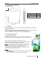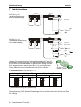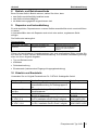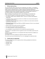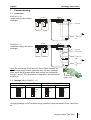
1
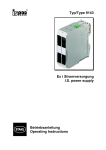
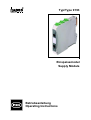
Typ/Type 9193
Einspeisemodul
Supply Module
Betriebsanleitung
Operating Instructions
Inhaltsverzeichnis
1
2
3
4
5
5.1
5.2
5.3
6
6.1
6.2
6.3
7
7.1
7.2
8
9
10
Sicherheitshinweise ....................................................................................................3
Normenkonformität .....................................................................................................3
Funktion ......................................................................................................................4
Kennzeichnung und technische Daten .......................................................................4
Projektierung...............................................................................................................5
Maximal zulässige Umgebungstemperaturen .........................................................5
Verlustleistung.........................................................................................................5
Projektierung der Verlustleistung in Schaltschränken .............................................6
Anordnung und Montage ............................................................................................7
Maßzeichnung.........................................................................................................7
Installation ...............................................................................................................7
Montage und Demontage........................................................................................7
Inbetriebnahme ...........................................................................................................8
Anschlüsse ..............................................................................................................8
Einstellungen (nur 9193/20-11-11)..........................................................................8
Betrieb- und Betriebszustände....................................................................................9
Reparatur und Instandhaltung ....................................................................................9
Zubehör und Ersatzteile..............................................................................................9
Contents
1
2
3
4
5
5.1
5.2
5.3
6
6.1
6.2
6.3
7
7.1
7.2
8
9
10
Safety instructions.....................................................................................................10
Conformity to standards............................................................................................10
Function ....................................................................................................................11
Marking and technical data .......................................................................................11
Engineering...............................................................................................................12
Max. ambient temperatures...................................................................................12
Power dissipation ..................................................................................................12
Engineering of the power dissipation in cabinets ..................................................13
Arrangement and fitting.............................................................................................14
Dimensions............................................................................................................14
Installation .............................................................................................................14
Installation advices ................................................................................................14
Commissioning .........................................................................................................15
Connection ............................................................................................................15
Settings (only 9193/20-11-11) ...............................................................................15
Operation and operational states..............................................................................16
Maintenance and repair ............................................................................................16
Accessories and spare parts.....................................................................................16
EG-Konformitätserklärung / EC-Declaration of Conformity .................................................17
Baumusterprüfbescheinigung ..............................................................................................18
Type Examination Certificate...............................................................................................19
2
deutsch
1
Betriebsanleitung
Sicherheitshinweise
In diesem Kapitel sind die wichtigsten Sicherheitsmaßnahmen zusammengefasst. Es
ergänzt die entsprechenden Vorschriften, zu deren Studium das verantwortliche Personal
verpflichtet ist.
Bei Arbeiten in explosionsgefährdeten Bereichen hängt die Sicherheit von Personen und
Anlagen von der Einhaltung aller relevanten Sicherheitsvorschriften ab. Das Montage- und
Wartungspersonal trägt deshalb eine besondere Verantwortung. Die Voraussetzung dafür
ist die genaue Kenntnis der geltenden Vorschriften und Bestimmungen.
Bei Errichtung und Betrieb ist Folgendes zu beachten:
• Es gelten die nationalen Montage- und Errichtungsvorschriften (z.B. EN 60079-14).
• Das Einspeisemodul ist in Zone 2, Zone 22 oder außerhalb explosionsgefährdeter
Bereiche zu installieren
• Bei Einsatz in Zone 2 ist das Einspeisemodul in ein Gehäuse einzubauen, das den
Anforderungen der EN 50 021 genügt.
• Bei Einsatz in Zone 22 ist das Einspeisemodul in ein Gehäuse einzubauen, das den
Anforderungen der EN 50 281 genügt
• Das Auswechseln der frontseitigen Sicherungen PWR1 und PWR2 (wenn vorhanden) ist
in der Zone 2 nur im spannungslosen Zustand zulässig.
• Die nationalen Sicherheits- und Unfallverhütungsvorschriften
• Die allgemein anerkannten Regeln der Technik
• Die Sicherheitshinweise dieser Betriebsanleitung
• Beschädigungen können den Explosionsschutz aufheben.
Verwenden Sie das Gerät bestimmungsgemäß, nur für den zugelassenen Einsatzzweck
(siehe „Funktion“).
Fehlerhafter oder unzulässiger Einsatz sowie das Nichtbeachten der Hinweise dieser
Betriebsanleitung schließen eine Gewährleistung unsererseits aus.
Umbauten und Veränderungen am Gerät sind nicht gestattet.
Das Gerät darf nur in unbeschädigtem, trockenem und sauberem Zustand eingebaut und
betrieben werden
2
Normenkonformität
Das Einspeisemodul Typ 9193 entspricht den folgenden Normen bzw. der folgenden
Richtlinie:
• Richtlinie 94/9/EG
• EN 50 021
• EN 61 326
• VDE 0110
Einspeisemodul Typ 9193
3
Betriebsanleitung
3
deutsch
Funktion
Das Einspeisemodul dient zur Hilfsenergieeinspeisung von 24 VDC / max. 4 A in den pacBus.
Bei der Varianten 9193/20 kann dies auch redundant, durch Dioden entkoppelt,
geschehen. Zusätzlich wird bei dieser Variante ein Hilfsenergie- oder Sicherungsausfall
über einen Relaiskontakt gemeldet.
Ein Leitungsfehler eines der am pac-Bus angeschlossenen Geräte wird als
Sammelmeldung auf einer Klemme zur Verfügung gestellt.
4
Kennzeichnung und technische Daten
Hersteller
Typbezeichnung
CE-Kennzeichnung
Ex-Kennzeichnung
Kennzeichnung Explosionsschutz
Prüfstelle und Bescheinigungsnummer
Umgebungstemperaturbereich
Technische Daten (Auszug aus dem Datenblatt)
Hilfsenergie
Eingang
Hilfsenergieeinspeisung
Max. Eingangsstrom
Ausgang
pac-Bus Einspeisung
Fehlermeldung
Hilfsenergieausfall (nur 9193/20)
Leitungsfehler
Umgebungsbedingungen
Betriebstemperatur
Lagertemperatur
relative Feuchte (keine Betauung)
R. STAHL
9193/*0-11-1*
c
e
II 3 G EEx nAC II T4
BVS 03 E 213 X
-20 °C … +70 °C
Ohne
24 VDC (18...31,2 V)
4A
24 V / max. 4 A
Relaiskontakt, 35 V / 100 mA
Relaiskontakt, 35 V / 100 mA
-20...+70 °C
-40...+80 °C
< 95 %
Weitere technische Daten sind dem aktuellen Datenblatt zu entnehmen.
Bei anderen vom Standard abweichenden Betriebsbedingungen nehmen Sie bitte
Rücksprache mit dem Hersteller.
4
Einspeisemodul Typ 9193
deutsch
5
Betriebsanleitung
Projektierung
5.1 Maximal zulässige Umgebungstemperaturen
Die Geräte der Reihe IS pac sind über einen weiten Temperaturbereich einsetzbar. Je
nach Geräteausführung und Einbaubedingung ergeben sich unterschiedliche, maximal
zulässige Umgebungstemperaturen.
Belüftung:
Ohne Umluft
Installation: Einzelgerät
Kanäle
Einbaulage: beliebig
1
DIN-Schiene
vertikal
horizontal
9193/10-11-10
9193/20-11-11
70 °C
60 °C
horizontal
65 °C
---
---
Mit Umluft
Installation: Einzelgerät
Einbaulage: beliebig
Kanäle
vertikal
Typ:
Belüftung:
1
pac-Träger
DIN-Schiene
vertikal
horizontal
pac-Träger
vertikal
horizontal
Typ:
9193/10-11-10
9193/20-11-11
70 °C
65 °C
70 °C
---
---
5.2 Verlustleistung
In den Datenblättern wird die max. Verlustleistung im Nennbetrieb (Ausgang max. 4 A;
Hilfsenergie 24 V DC) angegeben. Da in der Praxis nicht alle Geräte gleichzeitig unter
Volllast betrieben werden, erfolgt die Projektierung üblicherweise mit einer
durchschnittlichen Verlustleistung von 70 %. (P70%).
Typ
9193/10-11-10
9193/20-11-11
Kanäle
1
max. Verlustleistung 70 % Verlustleistung
2,5 W
1,8 W
Einspeisemodul Typ 9193
5
Betriebsanleitung
deutsch
5.3 Projektierung der Verlustleistung in Schaltschränken
Beim Einbau von Geräten innerhalb von Schaltschränken wird der freie Luftstrom begrenzt
und die Temperatur steigt. Um die Temperaturerhöhung zu minimieren, ist es wichtig, die
Verlustleistung sowie die produzierte Wärme innerhalb des Schrankes zu optimieren.
a) Natürliche Konvektion in geschlossenen Schränken
• Anwendung: bei geringer Verlustleistung und wenn das System in einer staubigen oder
rauen Umgebung installiert ist
• Berechnung der maximal zulässigen Verlustleistung:
Pmax = ∆t * S * K
Pmax [W]
∆t [°C]
S [m²]
K [(W/m²*°C)]
max. zulässige Verlustleistung im Schaltschrank
max. zulässige Temperaturerhöhung
freie, wärme-emittierende Oberfläche des Schaltschrankes
thermischer Leitfähigkeitskoeffizient (lackierter Stahl: K = 5,5)
Der errechnete Wert Pmax muss kleiner als die Summe der durchschnittlichen Verlustleistungen (70 % der max. Verlustleistung) der eingebauten Geräte sein: Pmax < ∑ P70%
b) Natürliche Konvektion in offenen Schränken
• Funktion: die Wärme wird mittels kühler Luftströme zwischen den Geräten verdrängt
• Voraussetzungen:
Luftein und – auslassöffnungen an den unteren und oberen Enden des
Schrankes
der Weg des Luftstroms muss frei von Hindernissen gehalten werden
• Ergebnis: Je nach Ausführung kann die doppelte zulässige Verlustleistung wie unter a)
erreicht werden.
c) Erzwungene Belüftung mit Wärmetauscher in geschlossenen Schränken
• Anwendung: wenn entweder die Umgebung oder die hohe Verlustleistung keine
natürliche Konvektion erlauben
• Funktion: ein Wärmetauscher mit Lüfter saugt Luft in den Schrank und drückt sie in die
Wärmetauscherplatten, die durch einen zweiten Lüfter mit Umgebungsluft gekühlt
werden
• Ergebnis: Je nach Ausführung kann die 5- bis 6-fache zulässige Verlustleistung wie
unter a) erreicht werden.
d) Erzwungene Belüftung in offenen Schränken
• Funktion: Ein oder mehrere Lüfter erzeugen einen Luftstrom von der unteren
Schranköffnung an den Geräten vorbei durch die obere Schranköffnung hinaus.
• Berechnung des notwendigen Luftstroms:
Q = (3,1 * P70%) / ∆t
Q [m³/h]
P70% [W]
∆t [°C]
notwendiger Luftstrom
entstehende Verlustleistung (70 % der max. Verlustleistung)
zulässige Temperaturerhöhung im Schaltschrank
e) Klimaanlage
• Anwendung: bei heißem Klima – eine Schranktemperatur gleich groß oder geringer als
die Umgebungstemperatur ist erreichbar.
• Funktion: Nutzung eines spezifisches Kältemaschinen-Systems oder des existierenden
Klimasystems für die Schrankkühlung.
6
Einspeisemodul Typ 9193
deutsch
6
Betriebsanleitung
Anordnung und Montage
6.1 Maßzeichnung
Schraubklemmen
Federzugklemmen
Schneid-Klemm
Technik
Maß X
104 mm
114 mm
115 mm
6.2 Installation
Das Einspeisemodul ist in der Zone 2, Zone 22 oder außerhalb explosionsgefährdeter
Bereiche zu installieren.
Bei Betrieb in Zone 2 bzw. Zone 22 ist das Einspeisemodul in ein Gehäuse einzubauen,
das den Anforderungen der EN 50 021 bzw. EN 50 281 genügt
(z.B. in ein Gehäuse Typ 8146 der Fa. R. STAHL Schaltgeräte GmbH)..
6.3 Montage und Demontage
a) Die abziehbaren Klemmen
Alle Geräte sind mit abziehbaren Klemmen versehen. Zum Abziehen die
Klemmen mit z.B. einem Schraubendreher wie im Bild dargestellt lösen.
b) Montage auf DIN-Schienen mit installiertem pac-Bus
Geräte wie im Foto dargestellt ansetzen und auf die DIN-Schiene mit
dem pac-Bus aufschwenken. Dabei nicht verkanten.
Hinweis: um eine Verpolung bei der Installation zu Verhindern, sind
die pac-Bus-Elemente mit einer Codierleiste (siehe Foto) und die
Module mit dem entsprechendem Codierschlitz versehen.
Zur Demontage den Fußriegel mit einem Schraubendreher etwas
herausziehen und das Modul entnehmen.
Hinweise:
Das Einspeisemodul kann an beliebiger Position auf dem pac-Bus
•
montiert werden.
•
Das Einspeisemodul ist nicht im pac-Träger einsetzbar.
Einspeisemodul Typ 9193
7
Betriebsanleitung
7
deutsch
Inbetriebnahme
7.1 Anschlüsse
pac-bus
9193/10-11-10
(einfache Einspeisung
ohne Ausfallmeldung)
LF
24 V LF
OK
+
LF
24 V
9
8
24 V
LF
OK
IS pac
IS pac
3-
PWR1
1+
pac-bus
9193/20-11-11
(redundante Einspeisung
mit Ausfallmeldung)
LF
Line Fault
24 V LF
OK
24 V
IS pac
OK
PF
9
8
7
6-
IS pac
LF
PF
PWR2
Line Fault
Power Fault
24 V DC
4+
+
3-
-
PWR1
1+
Hinweis: Zur Auswertung der Leitungsfehlermeldung LF der IS
pac Module über den pac-Bus und das Einspeisemodul (Klemme
8,9) muss die Fehlermeldekette im pac-Bus am Anfang und am
Ende abgeschlossen werden (pac-Bus Pin 3 und 4 gebrückt).
Dieser Abschluss ist im Klemmenset 9194/50-01 integriert.
24 V DC
+
+
LF
24 V
OK
-
24 V DC
+
9194/50-01
(Anfang + Ende)
7.2 Einstellungen (nur 9193/20-11-11)
Leitungsfehler Meldung LFS
unterdrückt
Aktiviert *)
OFF ON
LFS
SP
OFF ON
LFS
SP
Einspeisung SP
einfach
Redundant *)
OFF ON
LFS
SP
OFF ON
LFS
SP
*) Standardeinstellung bei Auslieferung
Die Änderung der DIP-Schalter-Einstellungen ist im Betrieb auch in der Zone 2 und Zone
22 zulässig.
8
Einspeisemodul Typ 9193
deutsch
8
Betriebsanleitung
Betrieb- und Betriebszustände
Bevor Sie das Gerät in Betrieb nehmen, stellen Sie sicher, dass
• das Gerät vorschriftsmäßig installiert wurde
• das Gerät nicht beschädigt ist
• die Kabel ordnungsgemäß angeschlossen sind
9
Reparatur und Instandhaltung
Es wird empfohlen, Reparaturen an unseren Geräten ausschließlich durch uns durchführen
zu lassen.
In Ausnahmefällen kann die Reparatur auch durch eine andere, zugelassene Stelle
erfolgen.
Die Geräte sind wartungsfrei.
Fehlersuchplan:
Fehlererkennung
LED „PWR1“ oder „PWR2“
erloschen
Fehlerursache
Hilfsenergie ausgefallen oder
Gerätesicherung defekt
Fehlerbehebung
Hilfsenergieversorgung kontrollieren.
Sicherungswechsel bei Betrieb in
Zone 2 nur im spannungslosen
Zustand!
Führen die beschriebenen Vorgehensweisen nicht zum gewünschten Erfolg, wenden Sie
sich bitte an unsere nächste Vertriebsniederlassung. Zur schnellen Bearbeitung benötigt
diese von Ihnen folgende Angaben:
• Typ und Seriennummer
• Kaufdaten
• Fehlerbeschreibung
• Einsatzzweck (insbesondere Eingangs-/Ausgangsbeschaltung)
10 Zubehör und Ersatzteile
Verwenden Sie nur Original-Ersatzteile der Fa. R.STAHL Schaltgeräte GmbH.
Benennung
pac-Bus
Beschreibung
Verdrahtung von Hilfsenergie und
Sammelfehlermeldung für Gerätegruppen IS
pac
Klemmenset für
5-polig, (Set Anfang + Ende) mit Brücke für
pac-Bus
Fehlermeldekette
DIN-Schiene
NS 35/15 (Meterware)
NS 35/7,5 (Meterware)
Netzgerät 240 V AC – Netzgerät zur Versorgung von IS pac Modulen
24 V DC / 5 A
bis 5 A; Installation auch in Zone 2 möglich.
Netzgerät 240 V AC – Netzgerät zur Versorgung von IS pac Modulen
24 V DC / 10 A
bis 10 A; Installation auch in Zone 2 möglich.
Bestellnummer
9194/31-17
9194/50-01
0616129
0616039
QUINT PS-100240AC/24DC/5/EX
QUINT PS-100240AC/24DC/10/EX
Einspeisemodul Typ 9193
9
Operating Instructions
1
english
Safety instructions
The most important safety instructions are summarised in this chapter. It is intended to
supplement the relevant regulations which must be studied by the personnel responsible.
When working in hazardous areas, the safety of personnel and plant depends on
complying with all relevant safety regulations. Assembly and maintenance staff working on
installations therefore have a particular responsibility. The precondition for this is an
accurate knowledge of the applicable regulations and provisions.
When installing and operating the device, the following are to be observed:
• The national installation and assembly regulations (e.g. EN 60079-14) apply
• The Supply module may be installed in Zone 2, Zone 22 or outside of the explosion
hazard area.
• If installed in Zone 2, the Supply module is to be fitted in an enclosure that meets the
requirements of EN 50 021.
• If installed in Zone 22, the Supply module is to be fitted in an enclosure that meets the
requirements of EN 50 281.
• Exchange of the front side fuses PWR1 and PWR2 (if present) in Zone 2 is only allowed
when deenergized.
• National safety and accident prevention regulations
• The generally recognized technical regulations
• The safety guidelines in these operating instructions
• Any damage can compromise and even neutralise the explosion protection.
Use the device in accordance with the regulations and for its intended purpose only (see
“Function”).
Incorrect or impermissible use or non-compliance with these instructions invalidates our
warranty provision.
No changes to the device impairing its explosion protection is permitted.
The device may only be fitted and used if it is in an undamaged, dry and clean state.
2
Conformity to standards
The Supply Module Type 9193 complies with the following standards and directives:
• Directive 94/9/EC
• DIN EN 50 021
• DIN EN 61 326
• VDE 0110
10
Supply module Type 9193
english
3
Operating Instructions
Function
The Supply module is used for power supply feed-in of 24 VDC / max. 4 A into the pacBus.
With versions 9193/20 a redundant supply, decoupled via diodes, is possible. Here a
power supply failure or a blown fuse is signaled via a relay contact, too.
A line fault of the modules installed on the pac-Bus is signaled as a common message at a
terminal.
4
Marking and technical data
Manufacturer
Type designation
CE marking
Ex marking
Explosion protection marking
Testing authority and certificate number
Ambient temperature range
Technical data (extract from the data sheet)
Power supply
Input
Power supply feed-in
Max. input current
Output
pac-Bus supply
Error message
Power failure (only 9193/20)
Line fault
Ambient conditions
Operating temperature
Storage temperature
Relative humidity (no condensation)
R. STAHL
9193/*0-11-1*
c
e
II 3 G EEx nAC II T4
BVS 03 E 213 X
-20 °C … +70 °C
none
24 VDC (18...31,2 V)
4A
24 V / max. 4 A
Relay, 35 V / 100 mA
Relay, 35 V / 100 mA
-20...+70 °C
-40...+80 °C
< 95 %
Additional technical data can be found in the current data sheet.
Please consult with the manufacturer before operating under conditions which deviate
from the standard operating conditions.
Supply module Type 9193
11
Operating Instructions
5
english
Engineering
5.1 Max. ambient temperatures
The IS pac isolators can be used over a wide temperature range. Depending on the
isolator version and installation method different maximum ambient temperatures may
result.
Ventilation:
without ventilation
Installation: Single unit
Channels
Orientation: any
1
DIN-rail
vertical
9193/10-11-10
9193/20-11-11
70 °C
60 °C
vertical
horizontal
65 °C
---
---
with ventilation
Installation: Single unit
Orientation: any
Channels
horizontal
Type:
Ventilation:
1
pac-Carrier
DIN-rail
vertical
pac-Carrier
horizontal
vertical
horizontal
Type:
9193/10-11-10
9193/20-11-11
70 °C
65 °C
70 °C
---
---
5.2 Power dissipation
Data sheets are describing the maximum power dissipation in standard operation (output
max. 4 A; power supply 24 V DC). In practice not all isolators are working with full load.
Therefore engineering is done typically with an average power dissipation of 70 % (P70%).
Type
9193/10-11-10
9193/20-11-11
12
Channels
1
Supply Module Type 9193
max. power dissipation
2.5 W
70 % power dissipation
1.8 W
english
Operating Instructions
5.3 Engineering of the power dissipation in cabinets
When electronic devices are integrated in cabinets free air movement is restricted and the
temperature rises. To minimise the temperature rise it is important to optimise the power
dissipation as well as the elimination of the produced heat inside a cabinet.
a) Natural Convection in closed cabinets
• Application: when the dissipated power is moderate and when the system operates in a
dusty or harsh environment
• Calculation of the maximum allowed power dissipation:
Pmax = ∆t * S * K
Pmax [W]
∆t [°C]
S [m²]
K [(W/m²*°C)]
max. allowed power dissipation in the cabinet
max. allowed temperature rise
free, heat emitting surface of the cabinet
thermal emitting coefficient (K=5.5 for painted steel sheets)
The calculated value for Pmax has to be smaller than the total average power dissipation
(70 % of max. power dissipation) of the installed isolators: Pmax < ∑ P70%
b) Natural convection in open cabinets
• Function: the heat is removed by cool air flowing through the devices
• Requirements:
- inlet and outlet ports in the lower and upper ends of the cabinet
- the air flow path must be kept free from obstacles.
• Result: Depending on the engineering the improvement can reach a two times higher
power dissipation as with a)
c) Forced ventilation with heat exchanger in closed cabinets
• Application: when either the harsh environment or the high dissipated power do not
allow natural convection
• Function: a heat exchanger with a fan pulls the air into the cabinet and pushes it into the
heat exchanger plates that are cooled by the external ambient air moved by a second
fan.
• Result: Depending on the engineering the improvement can reach a 5 or 6 times
higher power dissipation as with a)
d) Forced ventilation in open cabinets
• Function: the filtered air is taken from the bottom cabinet openings by one or more fans,
flows through the devices, and finally exits at the top of the cabinet.
• Calculation of the required air flow:
Q = (3.1 * P70%) / ∆t
Q [m³/h]
P70% [W]
∆t [°C]
required air flow
dissipated power (70 % of max. power dissipation)
allowed temperature rise in the cabinet
e) Air conditioned cabinets
• Application: for hot climates - it is possible to reach a cabinet temperature equal or even
lower than the ambient temperature
• Function: a specific refrigerating system or the existing air conditioning system can be
used for cabinet conditioning
Supply module Type 9193
13
Operating Instructions
6
english
Arrangement and fitting
6.1 Dimensions
X
Srew terminals
104 mm
Spring clamp terminals 114 mm
Insulation displacement 115 mm
connectors
6.2 Installation
The supply modules may be installed in Zone 2, Zone 22 or outside hazardous areas.
In the case of operation in Zone 2 or Zone 22 the supply modules must be fitted in an
enclosure which complies with the requirements of EN 50 021 or EN 50 281 (e.g. in an
enclosure type 8146 from the R. STAHL Schaltgeräte GmbH company).
6.3 Installation advices
a) Detachable terminals
All devices are provided with detachable terminals. A screwdriver is needed
to remove the terminals (as shown in the picture).
b) Mounting on DIN rails fitted with a pac-Bus
Set the device in position on the pac-Bus (already mounted on the DIN
rail) and tilt/snap until it locks in.
Do not tilt at an angle to either side when snapping onto the pac-Bus.
Note: In order to prevent pole reversal during installation, the pac-Bus
elements have been equipped with a keyed connection plug (see
photo). The module is fitted with a matching slot.
To dismount, use a screwdriver to gently pry up the lock on the mounting
foot and then remove the module
Notes:
•
•
The supply module can be installed on any position on the pac-Bus
The supply module can not be used in the pac-Carrier.
14
Supply module Type 9193
english
7
Operating Instructions
Commissioning
7.1 Connection
9193/10-11-10
(single supply without failure
message)
pac-bus
LF
24 V LF
OK
+
LF
24 V
9
8
24 V
LF
OK
IS pac
IS pac
3-
PWR1
1+
9193/20-11-11
(redundant supply with failure
message)
pac-bus
LF
Line Fault
24 V LF
OK
IS pac
24 V
OK
PF
9
8
7
6-
IS pac
LF
PF
PWR2
Line Fault
Power Fault
24 V DC
4+
+
3-
-
PWR1
1+
Note: For monitoring of line faults LF of the IS pac modules via
pac-Bus and supply module (terminals 8,9), the error message
chain has to be terminated at the start and the end (bridge pacBus pin 3 and 4). This termination is integrated in the terminal set
9194/50-01.
24 V DC
+
+
LF
24 V
OK
-
24 V DC
+
9194/50-01
(start + end)
7.2 Settings (only 9193/20-11-11)
Line Fault Message LFS
suppressed
activated *)
OFF ON
LFS
SP
OFF ON
LFS
SP
Power Supply SP
single
redundant *)
OFF ON
LFS
SP
OFF ON
LFS
SP
*) Default factory setting
Changing settings via DIP switches during operation is also permitted in Zone 2 and Zone
22.
Supply module Type 9193
15
Operating instructions
8
english
Operation and operational states
Before commissioning the device, please ensure that:
• the device has been installed in accordance with the standards
• the device is not damaged
• the cables are properly connected
9
Maintenance and repair
It is recommended that all repairs to our devices be carried out by R. Stahl. In exceptional
cases, repair may be performed by approved third-parties.
The devices are maintenance-free.
Troubleshooting chart:
Error detection
“PWR1” or “PWR2” LED
not lit
Malfunction cause(s)
Power supply failure or device fuse is
defective
Corrective action
Check power supply.
If device fuse is defective, deenergize
module (only when installed in Zone 2) and
exchange fuse.
If the procedure described above does not obtain the desired result, please contact your
local R.STAHL sales and service representative. In order to quickly process your request,
please provide us with the following information:
• Type and serial number
• Purchase date
• Description of malfunction
• Application description (particularly the configuration of the input/output circuitry)
10 Accessories and spare parts
Use only original spare parts from R. STAHL Schaltgeräte GmbH.
Name
pac-Bus
Terminal set for
pac-Bus
DIN rail
Power supply 240 V
AC – 24 V DC / 5 A
Power supply 240 V
AC – 24 V DC / 10 A
16
Description
Wiring for power supply and common error
messaging for groups of IS pac modules
5-pole, (set begin + end) with bridge for error
message chain
NS 35/15 (meter length)
NS 35/7.5 (meter length)
Power supply for the supply of IS pac modules
up to 5 A; Installation possible in Zone 2
Power supply for the supply of IS pac modules
up to 10 A; Installation possible in Zone 2
Supply module Type 9193
Ordering code
9194/31-17
9194/50-01
0616129
0616039
QUINT PS-100240AC/24DC/5/EX
QUINT PS-100240AC/24DC/10/EX
EG-Konformitätserklärung / EC-Declaration of Conformity
17
Baumusterprüfbescheinigung
18
Type Examination Certificate
19
R. STAHL Schaltgeräte GmbH
Am Bahnhof 30
74638 Waldenburg (Württ.) – Germany
www.stahl.de
ID-Nr. 91 936 01 31 0
S-BA-9193-002-de/en-10/2004