1
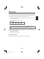
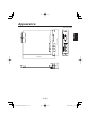
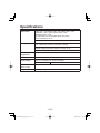
DVI/Analog Output board AV-HS04M5 Before operating this product, please read the instructions carefully and save this manual for future use. 01.AV-HS04M5_English.indd 1 日本語 РУССКИЙ ESPAÑOL ITALIANO FRANÇAIS Model No. DEUTSCH Operating Instructions ENGLISH cev.fr 2007/10/01 18:33:32 Contents Safety precautions ......................... Introduction ..................................... Accessory ....................................... Precautions for use ........................ Name of each part .......................... 1 5 5 6 7 Mounting ......................................... 8 Connections .................................. 11 Appearance ................................... 12 Specifications ............................... 13 Introduction When this board is installed in the AV-HS400N/E multi format line switcher, it enables one DVI-I output line and one analog output line to be supported. Any of five signals (PGM, PVW, AUX, KEYOUT and multi view display) can be selected as the output signals of each of the two lines. Accessory Operating instructions .................. 1 5 (E) 01.AV-HS04M5_English.indd Sec1:5 2007/10/01 18:33:39 Precautions for use Handle carefully. Use the product in an ambient temperature of 32 °F to 104 °F (0 °C to 40 °C). Avoid using the product at a cold place below 32 °F (0 °C) or at a hot place above 104 °F (40 °C) because extremely low or high temperature will adversely affect the parts inside. ENGLISH Do not drop the product, or subject it to strong shock or vibration. Power off before connecting or disconnecting cables. Before plugging or unplugging the cables, be sure to switch power off. Avoid humidity and dust. Avoid using the product at a humid, dusty place because much humidity and dust will cause damage to the parts inside. When the product is to be discarded When the product is to be discarded at the end of its service life, ask a specialized contractor to dispose of it properly in order to protect the environment. 6 (E) 01.AV-HS04M5_English.indd Sec1:6 2007/10/01 18:33:40 Name of each part Y Pb DVI / ANALOG OUTPUTS Pr DVI-I DVI-I output connectors [DVI OUTPUTS] When connected to the SLOT1 option output connector: OUTPUT3 When connected to the SLOT2 option output connector: OUTPUT5 Analog output connectors [ANALOG OUTPUTS] When connected to the SLOT1 option output connector: OUTPUT4 When connected to the SLOT2 option output connector: OUTPUT6 Setting switches 1 2 3 4 5 6 7 8 O N <Setting switch table> Switch no. 1 2 3 4 5 6 7 8 Reserved Reserved Reserved Reserved Reserved Reserved Reserved Reserved Off On Factory setting — — — — — — — — — — — — — — — — Off Off Off Off Off Off Off Off Use switches no. 1 to 8 at the “off” (factory setting) position. 7 (E) 01.AV-HS04M5_English.indd Sec1:7 2007/10/01 18:33:40 Mounting <Notes> Be sure to ask the store or dealer where you purchased the product for assistance with mounting and removal. Set to OFF and unplug the power connector before mounting and removal. Before handling this board, touch a metal part of the AV-HS400N/E to discharge the static electricity from the human body. An anti-static wrist strap is recommended for safety. Failures may be caused if you touch this board while you are still charged with static electricity. Keep the metal parts of this board free of contact with other metal parts. Be sure to mount the blank panel installed with the AV-HS400N/E, after removing this board. When installing or removing this board, take care not to hurt yourself on the edges and metal parts of the boards. ENGLISH Install this board in the multi-format live switcher AV-HS400N/E. Turn off the power of the AV-HS400N/E, and unplug the power cord. Loosen the two screws of SLOT1 or SLOT2 on the output side at the rear of the AVHS400N/E, and remove the blank panel. SLOT2 SLOT1 Blank panel Screw Screw 8 (E) 01.AV-HS04M5_English.indd Sec1:8 2007/10/01 18:33:40 Mounting Align the board with the guide rails, and insert it slowly. Insert it all the way in. Take care not to use force to insert the board because the connectors may be damaged in the process. Attach the board using the two screws. Screw Screw After connecting the necessary cables, plug in the power cord, and turn on the power. 9 (E) 01.AV-HS04M5_English.indd Sec1:9 2007/10/01 18:33:42 Mounting Turn on the power of the AV-HS400N/E, and use the menu used to display the statuses of the option boards to check that the board has been mounted correctly. Press the [FUNC] button to light its indicator, and press the [SYSTEM] button to display the SYSTEM menu. ENGLISH Checking that the board has been mounted correctly Turn [F1] to display the OptVer sub menu. <Menu display> OptVer 14/14 Select Board Version OUT-SL1 DVI/Ana Turn [F2] to select the option slot (OUT-SL1 or OUT-SL2) using the Select item. If the board has been mounted correctly, “DVI/Ana” will appear at the Board item. If it has not been mounted correctly, “None” will appear at the Board item. For details on the output signal settings and operating methods, refer to the operating instructions of the AV-HS400E. 4-4. Setting the output signals 4-9. Setting the DVI output signals Removal procedure Remove this board by following the procedures for mounting it in reverse. 10 (E) 01.AV-HS04M5_English.indd Sec1:10 2007/10/01 18:33:43 Connections Connections when not implementing gen-lock (frame synchronizer ON) HD Component HD component monitor HD SDI HD SDI monitor DVI or VGA PC monitor Multi-format live switcher AV-HS400N/E POWER UTIL OUTPUTS INPUTS SLOT2 UTIL6 UTIL5 SLOT1 UTIL4 UTIL3 Y Pb 8 6 DVI / ANALOG OUTPUTS DVI-I Pr 7 5 SLOT2 SLOT1 DVI INPUTS DVI-I ON DVI-I OFF SLOT 2 SLOT 2 㨪IN Y Pb ANALOG OUTPUTS Y Pr Pb Y Pr ANALOG INPUTS Y Pr Pb Pb Pr SLOT 1 SLOT 1 SDI OUTPUTS SDI INPUTS PGM UTIL2 UTIL1 2 1 3 4 OUT IN OUT 2 IN OUT SIGNAL GND 1 IN OUT IN ETHERNET RS422 REF TALLY GPI Power cord HD SDI HD SDI HD camera VTR HD SDI HD SDI HD camera VTR HD SDI HD camera Make the connection with this board while the power is off. For details on connecting individual devices, refer to the respective operating instructions. For details on operating individual devices, refer to the respective operating instructions. 11 (E) 01.AV-HS04M5_English.indd Sec1:11 2007/10/01 18:33:43 Appearance ENGLISH DVI / ANALOG OUTPUTS Pr Y Pb 5-2/16 (130) DVI-I Unit: Inch (mm) 1-1/16 (27) 6 (152.5) 12 (E) 01.AV-HS04M5_English.indd Sec1:12 2007/10/01 18:33:44 Specifications DVI-I output XGA 1024 × 768, WXGA 1280 × 768, SXGA 1280 × 1024, WSXGA+ 1680 × 1050, UXGA 1600 × 1200, WUXGA 1920 × 1200 (: Selectable only when digital signals are output) Vertical frequency: 60 Hz DVI-I ×2 Analog output SD: 480/59.94i, 576/50i HD: 1080/59.94i, 1080/50i, 720/59.94p, 720/50p SD/HD analog component Y/Pb/Pr (1.0 Vp-p, 75 ) BNC ×1 Ambient operating 32 °F to 104 °F (0 °C to 40 °C) temperature Humidity 10 % to 90 % (no condensation) Power supply DC 12 V (supplied from the AV-HS400N/E) Power consumption ?? W Dimensions (W H D) 6˝ × 1-1/16˝ × 5-2/16˝ (152.5 × 27 × 130 mm) Weight 0.4 lbs. (0.2 kg) 13 (E) 01.AV-HS04M5_English.indd Sec1:13 2007/10/01 18:33:45