1
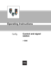
Operating Instructions
Indicating lamps for
panel mounting
> 8013/3
Contents
1
Contents
1
2
3
4
5
6
7
8
9
10
11
12
13
14
2
Contents ................................................................................................................2
General Information ...............................................................................................2
Safety instructions .................................................................................................3
Conformity to Standards ........................................................................................3
Function of the Indicating Lamps for Panel Mounting Type 8013/3 ......................4
Technical Data ......................................................................................................4
Arrangement and Fitting ........................................................................................6
Installation .............................................................................................................7
Servicing ..............................................................................................................10
Transport and Storage ........................................................................................11
Disposal ...............................................................................................................11
Type Examination Certificate (Page 1) ................................................................12
Declaration of Conformity ....................................................................................14
IOM sheet ............................................................................................................16
General Information
2.1 Manufacturer
R. STAHL Schaltgeräte GmbH
Am Bahnhof 30
D-74638 Waldenburg
Phone:
Fax:
Internet:
+49 7942 943-0
+49 7942 943-4333
www.stahl.de
2.2 Information regarding the Operating Instructions
ID NO.:
8013603300
Publication Code:
S-BA-8013/3-02-en-14/05/2008
We reserve the right to make technical changes without notice.
2.3 Symbols
Caution!
This symbol marks notes whose non-observance will endanger your health or the
functioning of the device.
)Note
This symbol marks important additional information, tips and recommendations.
2
Indicating lamps for panel mounting
8013/3
8013603300
S-BA-8013/3-02-en-14/05/2008
Safety instructions
3
Safety instructions
The most important safety instructions are summarised in this section. They supplement
the corresponding regulations which the personnel in charge must study.
When working in areas subject to explosion hazards, the safety of personnel and plant
depends on complying with all relevant safety regulations. Assembly and maintenance
staff working on installations therefore have a particular responsibility. A precise
knowledge of the applicable standards and regulations is required.
As the user, please note:
X national safety and accident prevention regulations,
X national assembly and installation regulations (e.g. IEC/EN 60079-14),
X generally recognised technical regulations,
X safety instructions and information in these operating instructions,
X characteristic values and rated operating conditions on the rating and data plates,
X that when fitting the device type 8013/3.2 into enclosures with type of protection
“Increased Safety e“, the conditions given in IEC/EN 60079-0 and IEC/EN 60079-7
must be observed.
X that the backs of the devices types 8013/3.1 and 8013/3.3 must be protected against
mechanical damage,
X that any damage of the fixture can invalidate the Ex protection.
Use the devices in accordance with their designated use and for their intended purpose
only ("Function of the indicating lamps for panel mounting" type 8013/3 on page 4).
Incorrect and impermissible use or non-compliance with these operating instructions
invalidates our warranty provision. No modifications or alterations to the devices or
components, impairing their explosion protection, are permitted. The devices and
components may only be fitted if they are undamaged, dry and clean.
4
Conformity to Standards
The panel-mounting fixtures comply with the following standards and directive:
Types 8013/3.1 and 8013/3.3:
X Directive 94/9/EC
X IEC/EN 60079-0, IEC/EN 60079-1, IEC/EN 60079-11, IEC/EN 60079-18,
IEC/EN 60079-7
X IEC/EN 61241-0, IEC/EN 61241-1
X EN 60947-1, EN 60947-5-1, EN 61210-6
X EN 50007, EN 60999-1, EN 60825-1, EN 50081-2, EN 61000-6-2
panel-mounting fixtures are approved for use in hazardous areas of
)The
zones 1, 2, 21 and 22.
8013603300
S-BA-8013/3-02-en-14/05/2008
Indicating lamps for panel mounting
8013/3
3
Function of the Indicating Lamps for Panel Mounting Type 8013/3
Type 8013/3.2:
X Directive 94/9/EC
X IEC/EN 60079-0, IEC/EN 60079-1, IEC/EN 60079-11, IEC/EN 60079-18,
IEC/EN 60079-7
X EN 60947-1, EN 60947-5-1, EN 61210-6
X EN 50007, EN 60999-1, EN 60825-1, EN 50081-2, EN 61000-6-2
panel-mounting fixtures are approved for use in areas subject to explosion hazards
)The
of zones 1 and 2.
5
Function of the Indicating Lamps for Panel Mounting Type 8013/3
The indicating lamps signal command modes in load, control and signal circuits by
lighting up or going out. They are designed for single-hole fixing D 30 according to
EN 50007 in combination with indicating lamp inserts type 8602/3.2.
Indicating lamp types 8013/3.1 and 8013/3.3 are explosion-protected, electrical devices.
They are suitable for mounting in enclosure panels, electrical device covers,
switchboards or control cubicles (type of protection “Increased Safety e“
acc. to IEC/EN 60079).
Indicating lamps type 8013/32. are “intrinsically safe“ and are used in intrinsically safe
circuits.
6
Technical Data
Explosion protection
Gas explosion protection
Gas explosion protection
(IECEx)
4
Ex e
8013/311
8013/312
8013/313
E II 2 G Ex de mb IIC T6
E II 2 G Ex de mb IIC
E II 2 G Ex de mb IIC T6
Ex i
8013/321
8013/322
8013/323
E II 2 G Ex d mb ia IIC T6
E II 2 G Ex d mb ia IIC
E II 2 G Ex d mb ia IIC T6
Ex e
8013/311
8013/312
8013/313
Ex dem IIC T6
Ex dem IIC
Ex dem IIC T6
Ex i
8013/321
8013/322
8013/323
Ex dm ia IIC T6
Ex dm ia IIC
Ex dm ia IIC T6
Dust explosion protection
8013/3.1
8013/3.3
E II 2 D Ex tD A21 IP 65 T80 °C
Dust explosion protection
(IECEx)
8013/3.1
8013/3.3
E II 2 D Ex tD A21 IP 65 T80 °C
Certificates
8013/3.1
8013/3.2
8013/3.3
PTB 02 ATEX 2131 X
PTB 02 ATEX 2130 U
PTB 02 ATEX 2131 X
IECEx certification
8013/3.1
8013/3.2
8013/3.3
IECEx PTB 07.0010 X
IECEx PTB 07.0012 U
IECEx PTB 07.0010 X
Ambient temperature
- 30 °C ... + 60 °C
Rated voltage
Ex e
Ex i
12 V - 10 % ... 254 V + 6 % AC / DC
10.8 V ... 28 V DC
Indicating lamps for panel mounting
8013/3
8013603300
S-BA-8013/3-02-en-14/05/2008
Technical Data
Rated current
0.014 A at 24 V DC
Frequency
0 Hz ... 60 Hz
Rated power
0.6 W
Colours
red, yellow, green, blue, white
Colour filtering via coloured insert caps
Connection type
Connection cross-section:
8013/3.1
0.75 mm2 ... 1.5 mm2
8013/3.2
0.50 mm2 ... 2.5 mm2
8013/3.3
2 x 0.75 mm2 connecting cable
Cable entry
Type 8013/3.1:
M16 x 1.5 (d 4 - 9 mm)
Ingress Protection
Degree of protection acc. to IEC 60529
8013/3.1+8013/3.3
8013/3.2
Electrical life
105 lighting hours
Material
Polyamide
Weight
0.119 kg with actuator
IP 66
IP 66 / IP 20 (connections)
Additional electrical data for intrinsically safe version type 8013/3.2
Safety-specific maximum
values
Ui 28 V, Ii 150 mA, Pi 1 W, inductivity Li and capacity Ci negligible
Binary output
STAHL 9175/10-16-11
STAHL 9175/20-16-11
Safety barrier
STAHL 9001/01-280-110-101
one duct
two ducts
)Please consult the manufacturer if operating conditions are non-standard.
The indication lamps can be supplied in three versions:
)Type
8013/3.1 with terminal compartment
Type 8013/3.2 without terminal compartment
Type 8013/3.3 with terminal compartment and internal cable
8013603300
S-BA-8013/3-02-en-14/05/2008
Indicating lamps for panel mounting
8013/3
5
Arrangement and Fitting
7
Arrangement and Fitting
7.1 Dimensional Drawings
(all dimensions in mm) - subject to alterations
03314E00
8013/3.1 and 8013/3.3
Indicating lamp with terminal
compartment
04825E00
8013/3.2
Indicating lamp without terminal
compartment
04488E00
Cut-out for aligning several devices
d 38 mm in a panel
7.2 Assembly
The devices are suitable for fitting into enclosure panels or switchboards with a panel
thickness of 1.0 ... 6.5 mm. The fitting hole diameter is 30.5 mm.
Single-hole fitting
Lamp insert
Panel into which
device is fitted
Threaded nut
Seal
04857E01
Fig. 7-1: Single-hole fitting
When fitting please note that:
The indicating lamp may not be set at an angle!
The indicating lamp base and lamp insert must be firmly set into the panel!
The accompanying seal must be inserted and precisely seated!
X Push the lamp insert into the panel from the front and lock it in position.
X Push the indicating lamp base onto the lamp insert from the back of the panel.
X Tighten the lamp insert against the panel to which it is fitted by turning the threaded
nut.
X Obtain the lamp colour required by selecting the correctly coloured insert cap.
6
Indicating lamps for panel mounting
8013/3
8013603300
S-BA-8013/3-02-en-14/05/2008
Installation
Changing the insert cap colour
11354E00
Fig. 7-2: Changing the insert cap colour
X Push a screwdriver (blade 0.6 x 3.5 form A to DIN 5264 or ISO 2380-1) into the slot
and turn it.
X Pull the insert cap out.
X Snap the new insert cap in.
8
Installation
8.1 Mains Connection
Ensure that the maximum permissible conductor temperatures are not exceeded by
suitable selection of cables and means of running them. Pease also take note of the
information on connections (see “Technical Data“ on page 5).
Particular care should be taken when making the connections.
Indicating lamps types 8013/31. and 8013/32. have screwless terminals for mains
connections. Indicating lamp type 8013/33. is fitted with a plastic-sheathed cable.
X Cable cross-sections:
Type 8013/3.1: 0.75 ... 1.5 mm2
Type 8013/3.2: 0.50 ... 2.5 mm2
Type 8013/3.3: 2 x 0.75 mm2
04865T00
X Usable copper conductors: single wire, stranded - normal,
fine or very fine
Fig. 8-1: Terminal arrangement
note that when connecting the free end of the cable to the main supply within an
)Please
area subject to explosion hazards, the connection must be made in a type of protection
corresponding to the zone.
8013603300
S-BA-8013/3-02-en-14/05/2008
Indicating lamps for panel mounting
8013/3
7
Installation
Cable entry on indicating lamp 8013/3.1
Use plastic sheathed cables with an external diameter of 5 ... 9 mm.
11612T00
Fig. 8-2: Cable entry on indicating lamp 8013/3.1
X Push the cable into the cable gland from behind (1).
X Push the cable into the connection cover until there is a sufficient length left free on the
other side to enable connections to be prepared (2).
Preparing the cable for type 8013/3.1
11613T00
Fig. 8-3: Preparing the cable for indicating lamp type 8013/3.1
X Remove a 40 mm length of sheath.
X Remove a 6 mm length of conductor insulation.
To maintain the creepage distances, ensure that exactly 6 mm of insulation are
removed. Note that the conductor must not be damaged (nicked) when the insulation is
removed.
Cable connections to screwless terminals
11614T00
Fig. 8-4: Cable connection to screwless terminals (types 8013/3.1 and 8013/3.2)
X Cross-section view of screwless terminal (1).
X Open (2) the terminal with a screwdriver (blade 0.6 x 3.5 form A to DIN 5264 or
ISO 2380-1).
X Führen Sie den vorbereiteten Leiter ein (3). Die Schraubendreherschneide hält die
WAGO CAGE CLAMP- Compact Feder geöffnet, so dass der Leiter eingeführt werden
kann.
X Remove the screwdriver. The conductor is securely clamped (4).
8
Indicating lamps for panel mounting
8013/3
8013603300
S-BA-8013/3-02-en-14/05/2008
Installation
Closing the connection area of indicating lamp type 8013/3.1
11615T00
Fig. 8-5: Terminal compartment open
11616T00
11617T00
Fig. 8-6: Pushing the connection cover on
X
X
X
X
Push the connection cover onto the terminal carrier (1) until it latches into position.
Push the cable towards the connection cover (2).
Tighten the gland nut to a torque of approx. 1.3 Nm.
The terminal compartment is now sealed.
As the user, please note:
Cables must be fixed in position and
a suitable tension relief provided.
Opening the connection area of indicating lamp type 8013/3.1
You can only open the connection area cover with a suitable tool.
11618T00
Fig. 8-7: Opening the connection area of type 8013/3.1
X
X
X
X
X
Position the screwdriver with blade 0.6 x 3.5 against one of the latching tabs.
Turn it by 90°.
Pull the cover back a little and hold it in this position.
Position the screwdriver against the second latching tab and turn it by 90°.
Pull the cover off.
8013603300
S-BA-8013/3-02-en-14/05/2008
Indicating lamps for panel mounting
8013/3
9
Servicing
8.2 Commissioning
Before commissioning, ensure that
X the connections have been correctly made,
X the indicating lamp has been fitted in accordance with the standards,
X the indicating lamp is not damaged.
9
Servicing
9.1 Maintenance
Maintenance work on the devices may only be carried out by appropriately authorised
and trained personnel.
Before any work commences, the devices must be disconnected from the supply.
The following must be checked during maintenance:
X
X
X
X
that the cable is securely seated,
plastic enclosure for the formation of cracks,
the cable entry seal for damage,
the function according to its designated use.
)Observe the relevant national regulations in the country of use!
9.2 Accessories and Spare Parts
Use only original accessories and spart parts from R. STAHL Schaltgeräte GmbH.
Use of another company´s accessories and spare parts invalidates the warranty of
R. STAHL Schaltgeräte GmbH.
Designation
Illustration
Description
Order number
Weight
kg
Additional front label
05543E00
Label mount, size 1, without symbol label
Text: 1 line
8602904800
0,002
Label mount, size 2, without symbol label
Text: 1 or 2 lines
8602907800
0,003
Label mount, size 3, without symbol label
Text: 1, 2 or 3 lines
8602920800
0,004
––
for actuator inserts to fit standard d 30.5 mm holes
Symbol labels:
without text
with text; please specify text
HAND - 0 - AUTO
OFF - ¸ - ON
0-I
I - II
round, d 30.5 mm, with transparent lens
Calotte
I - 0 - II
0 - I - II
0 - Operation - I
0-¸-I
8602912580
0,015
05038E00
10
Indicating lamps for panel mounting
8013/3
8013603300
S-BA-8013/3-02-en-14/05/2008
Transport and Storage
Designation
Illustration
Description
Order number
Weight
red
8602920580
0,001
yellow
8602919580
0,001
kg
Cap
05039E00
Closing part
green
8602921580
0,001
blue
8602922580
0,001
white
8602918580
0,001
all colours
8602806580
0,005
to close not used mounting holes d 30.5 mm
8602801587
0,016
05647E00
10 Transport and Storage
Transport and storage are only permitted in the original packing.
11 Disposal
Observe the national standard for refuse disposal.
8013603300
S-BA-8013/3-02-en-14/05/2008
Indicating lamps for panel mounting
8013/3
11
Type Examination Certificate (Page 1)
12 Type Examination Certificate (Page 1)
12
Indicating lamps for panel mounting
8013/3
8013603300
S-BA-8013/3-02-en-14/05/2008
Type Examination Certificate (Page 1)
8013603300
S-BA-8013/3-02-en-14/05/2008
Indicating lamps for panel mounting
8013/3
13
IOM sheet
14 IOM sheet
R. STAHL, INC.
INSTALLATION OPERATION
& MAINTENANCE SHEET
9001 Knight Road
Houston, TX 77054
Tel: 800-782-4357 FAX: 713-792-9301
E-mail: [email protected]
Website: www.rstahl.com
Series 8013/31
Panel Mounted LED Pilot Lights
Please read this entire document
before beginning any work.
3. Installation of the LED Pilot Lights
Installation and maintenance of these LED Pilot Lights
should only be performed by qualified personnel in
accordance with the National Electrical Code (NEC)
(NFPA 70) or the Canadian Electrical Code (CEC) and
any applicable code regulations.
The of LED Pilot Lights 8013/31• are incomplete, explosion protected electrical devices which are typically
installed in an electrical panel or enclosure. The types of
enclosures needed for the different area classifications
indicated in the left column of the table below, are stated
in the middle or right column.
CAUTION:
Enclosure Type Rating For Installation
Area Classification
of Use
• Operate only undamaged devices with observations
of the operating parameters in Section 2.
Class I, Zone 1
2. Technical Data
Class I, Division 2
Groups A, B, C, & D
Please refer to the technical data on the device.
2.1 Certifications
File No. E182378
Class I, Zone 1, AEx dem IIC T6
Class I, Zone 1, Ex dem IIC T6
Class I, Div. 2, Groups A,B,C & D
16
Indicating lamps for panel mounting
8013/3
Enclosure AEx e
or Ex e
Enclosure Type 1, 2 ,3, 3R, 4, 4X, 12, 13
.13”
(3.5mm)
3.1 Punching Knock-outs
• Punch 1.2" diameter
knock-outs (30.5mm)
into the panel. The
LED Pilot Lights can
be mounted into
walls between
0.04 - 0.25"
(1.0 … 6.5mm)
2.2
2.3
2.4
80 136 04 30 0
Enclosure Type➀ 1, 2, 3, 3R,
4, 4X, 12, 13
Pilot Light with Cage Clamps
8013/312 (without Cap)
➀Terminate leads in AEx e Terminal Box
See information on the device
Ambient temperature range: -30°C to +55°C.
Storage temperature range: -55°C to +100°C.
Environmental protection type: 3, 4; 4x
IP66/IP20 at terminals depending on enclosure
(see section 3).
2.5 General electrical data:
2.5.1 Cage clamp terminal capacity: 2x 18 AWG
to 2x 12 AWG
2.5.2 Rated operating voltage: 12-254V AC/DC
2.5.3 Frequency: 0 - 60Hz
2.5.4 Rated operating current: 0.014A @ 24V DC
2.5.5 Rated power: 0.6W
2.5.6 Light source: LED white
2.5.7 Colors: There are five lenses included in the
package: red, yellow, green, blue and white. One
of them should be snapped over the clear bezel.
(See Section 3.3).
Pilot Light with Cap 8013/311 or
with Cap & Lead 8013/313
.66”
(17mm)
• Disconnect power supply before installing or servicing these devices.
I.D.1.2”
(30.5mm)
1. Safety Instructions
• Observe the clearances.
1.65”
(42mm)
3.2 Removing the bezel:
• Turn the retainer nut
counter-clockwise as far
as it will go.
• Pull off the bezel.
3.3 Changing out the colored
lens:
Use screwdriver with a blade
of 0.6 x 3.5 mm push it into the
slot and turn it. Pull off the lens
and snap on the other.
When installing the LED Pilot Lights with terminal
cap, type 8013/311, skip section 4.
1/3
December 13, 2006
8013603300
S-BA-8013/3-02-en-14/05/2008
IOM sheet
R. STAHL, INC.
INSTALLATION OPERATION
& MAINTENANCE SHEET
9001 Knight Road
Houston, TX 77054
Tel: 800-782-4357 FAX: 713-792-9301
E-mail: [email protected]
Website: www.rstahl.com
4. Installation of the LED Pilot Light 8013/312
into the panel.
5. Installation of the LED Pilot Light 8013/311
into the panel.
4.1 Dimensions
5.1 Dimensions
• Push the bezel from the front through the panel
knock-out making sure the gasket is seated flat
against the panel and lock
it in position.
5.2 To open the terminal cap use a screwdriver with
blade of 0.6 x 3.5 mm.
• Align the LED block to the
three tabs of the bezel part
and snap them together.
• Position the screwdriver against one of the locking
tabs.
• Tighten the retainer nut against the panel.
• Turn it 90°.
• Pull the cap back a
little and hold it in this
position.
4.2 Cage clamp terminals
• Capacity 2 x 18 to 2 x 12 AWG.
• Position the screwdriver against the
second locking tab.
4.3 Conductor connection to cageclamp terminals.
• Turn it 90°.
1. Cut-away, showing cage-clamp terminals with capacity of 2 x 18 to 2 x 12
AWG.
2. Open cage-clamp with a screwdriver
(blade – 0.6 x 3.5mm) by inserting it
into the square opening and hold the
clamp open.
• Pull the cap off.
5.3 Use flexible cord with O.D. 0.2" to 0.35"
3. Insert the conductor into one of the
rounded openings.
1
4. Remove the screw driver.
2
• Open the cable gland.
• Slide the cord through the cable gland.
When installing the LED Pilot Light without terminal cap
8013/312, skip section 5.
80 136 04 30 0
8013603300
S-BA-8013/3-02-en-14/05/2008
• Pull the cord into the terminal cap.
2/3
December 13, 2006
Indicating lamps for panel mounting
8013/3
17
IOM sheet
R. STAHL, INC.
INSTALLATION OPERATION
& MAINTENANCE SHEET
9001 Knight Road
Houston, TX 77054
Tel: 800-782-4357 FAX: 713-792-9301
E-mail: [email protected]
Website: www.rstahl.com
5.4 Prepare the cord.
5.7 Mounting the LED Pilot Light into the panel
Bezel &
Colored Lens
1.57" (40mm)
Panel
Retainer Nut
0.25"
(6mm)
• Remove the outer jacket for the length of the cable
gland.
Gasket
• Strip off the insulation of the conductor 0.25".
• Push the bezel
from the front
through the
panel knock-out
making sure
the gasket is
seated flat
against the
panel and lock
it in position.
5.5 Conductor connection to cage-clamp terminals.
1. Cut-away, showing cage-clamp terminals with capacity of 2 x 18 to 2 x 12
AWG.
2. Open cage-clamp with a screwdriver
(blade – 0.6 x 3.5mm) by inserting it
into the square opening and hold the
clamp open.
3. Insert the conductor into one of the
rounded openings.
4. Remove the screw driver.
Cable Gland
• Align the LED block to the three tabs of the bezel
and snap them together.
• Tighten the retainer nut against the panel.
6. Maintenance
The only maintenance is a periodic inspection for
damage and proper operation. Any damaged parts
of the LED Pilot Lights and the panel need to be
replaced promptly to ensure the electrical safety and
explosion protection of the system.
5.6 Closing the terminal cap.
7. Parts and Accessories
Use only original spare parts and accessories, any
others would invalidate the certification and warranty.
Image
Description
Catalog Number
Bezel
clear
white
yellow
red
green
blue
all above colors
Close-up plug for
unused openings
Lens
• Push the terminal cap onto the
LED block until it locks into position.
• Push the cord toward the cable
gland.
• Tighten the gland nut with 11 in. lbs. (1.2 Nm) torque.
86
86
86
86
86
86
86
029
029
029
029
029
029
028
12
18
19
20
21
22
06
58
58
58
58
58
58
58
0
0
0
0
0
0
0
86 028 01 58 7
Note:
The nature of these instructions is only informative and does not cover all of the details, variations or combinations in which this equipment may be
used, its storage, delivery, installation, safe operation and maintenance.
Since conditions of use of the product are outside of the care, custody and control of the manufacturer, the purchaser should determine the suitability
of the product for his intended use, and assumes all risk and liability whatsoever in connection therewith.
80 136 04 30 0
18
Indicating lamps for panel mounting
8013/3
3/3
December 13, 2006
8013603300
S-BA-8013/3-02-en-14/05/2008
8013603300
S-BA-8013/3-02-en-14/05/2008