1
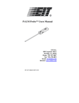
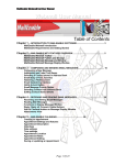
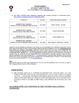
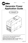
STATIC LEVEL MONITORING
SYSTEM
Model 624
Operating Manual
5/09
1.0 INTRODUCTION
Electrostatics is the oldest form of electrical phenomena known, but probably the least
understood and the most difficult to control. Static electricity occurs because a material
has a surplus (-) or a deficiency of electrons (+). Static electricity is generated by the
separation of materials such as pulverized material passing through chutes or
pneumatic conveyers, power or conveyer belts in motion, motion of all sorts that involve
changes in the relative position of contacting surfaces, usually of dissimilar substances,
liquid or solid, one of which is usually a poor conductor of electricity. In general, the
lower the electrical conductivity of the material and ambient relative humidity, the
greater the static charge generation.
The generation of static charge cannot be prevented absolutely because its intrinsic
origins are present at every interface. It is often the ignition source for an ignitable
mixture in many unexplained explosions or flash fires. The problem is particularly acute
in size reduction operations such as milling or pulverizing, the movement of particles
through conveyers and pipes, and the high speed processing of sheet and roll material.
The resultant materials are often highly charged and potentially dangerous or disruptive
to the manufacturing process.
The development of electrical charges may, in itself not be a potential explosion hazard.
There must be a discharge or sudden recombination of separated positive and negative
charges. In order for static electricity to be a source of ignition, four conditions must be
fulfilled:
1.
There must be a source of static electric generation.
2.
There must be a means of accumulating charge and maintaining a sufficient
difference of electrical potential.
3.
There must be a spark discharge of sufficient energy.
4.
The spark must occur in an ignitable mixture.
The ignitable mixture could be from fumes emanating from a solvent used in the
process or, as in many situations, from the dust cloud developed from the material itself.
Operations where the above conditions can exist are hammer mills; storage or
transporting facilities such as tanks, hoppers, grain elevators, tankers and barges;
compounding and calendering of plastics; chemical and petrochemical plants, and
fueling facilities.
The ability of a spark to produce ignition is governed largely by its energy, which will be
some fraction of the total stored energy. The energy in a static discharge is expressed
as
E= ½CV² Joules
where C is the capacitance in Farads and V is the potential difference in Volts. The
magnitude of electrostatic voltage encountered in industry can range anywhere from a
few volts to several hundred thousand volts. The capacitance of an object depends
upon its physical dimensions and its proximity to adjacent objects. Generally, the
capacitance of pieces of machinery is estimated to range from 100 to more than 1000
1
pf. The capacitance of the human body generally ranges between 100 to 300 pf. Tests
(NFPA 77 – Static Electricity) have shown that saturated hydrocarbon gases and vapors
require approximately 0.25 milliJoules of stored energy for spark ignition of optimum
mixtures with air. In normal industrial environments, minimum voltages of approximately
several thousand (1.5–5kV) would be required. Many industrial standards limit the
maximum voltage to 500–4000 Volts.
For dust clouds the minimum ignition energy ranges from approximately 10 to over 100
mJ for many common foodstuffs and resins. In normal industrial environments, voltages
ranging from under 5kV to over 20 kV would be required.
In practically every situation the capacitance of a system is fixed which means that the
ignition energy is a function of the voltage generated. The voltage levels are a function
of several factors, but for a given material, the lower the humidity, the higher the voltage
generated. In most industrial operations the voltage levels generated by a material
cannot be totally controlled. However, it is possible to monitor the electrostatic voltage
level, and when dangerous levels are reached an alarm and/or a countermeasure can
be activated.
Another critical area affected by static charge build-up is in the manufacture of material
using high speed machinery such as fabric, nonwoven and plastic webs, extruding and
calendering processes, slitting and rewinding operations, paper handling, printing, etc.
In many of these processes, the build-up of static charge can be controlled locally by
passive, electronic or nuclear ionization. However, when ionizer performance
deteriorates (dirt build-up on the ionizer points) or fails, costly machine downtime
caused by static electricity can occur.
Finally, many electronic devices are highly susceptible to electrostatic discharge.
Exposure to an ESD event can damage or destroy electronic equipment. Many devices
today are sensitive to static discharges less than 200 Volts and new technology devices
being sensitive to less than 30 Volts. Many automatic handling machines will generate
static charges in excess of these levels resulting in decreased product reliability.
The Model 624 Static Level Monitor is specifically designed to monitor the static charge
build-up and to activate alarm(s) or countermeasure(s) when the level exceeds preset
thresholds.
2.0 EQUIPMENT DESCRIPTION
2.1
General
The Model 624 shown in Figure 2.1-1 is a multi-channel static level monitor that
consists of a control unit and remote sensors. The system can be configured to
meet most user applications. The standard Model 624 is designed for use in
nonhazardous locations.
2
Figure 2.1-1: Standard Model 624 (2-CH version)
For Class I, II or III applications where intrinsically safe apparatus has been
approved, the Model 624 can be made intrinsically safe. The standard system is
fitted with 1/8” NPT tapped and plugged holes in the sensor as shown in Figure
2.1-2 for those applications that permit an air purge. In certain applications where
a threaded Teflon insert is permitted in an explosion-proof sensor housing, then
this type of housing can be provided for custom designed systems.
Figure 2.1-2: Standard Charged Plate Detector Sensor
3
When high sensitivity in a clean environment is required, such as electronic
assembly operations, the Model 624 is available with an open detector sensor
shown in Figure 2.1-3 that increases the basic system sensitivity by a factor of 10
or a modified standard system with closer sensor-object spacing that also
increases the sensitivity by a factor of 10.
Figure 2.1-3: High Sensitivity Open Detector Sensor
2.1.1 Control Unit
The control unit is housed in an ABS enclosure with a clear, gasketed,
polycarbonate door that provides sealing up to NEMA 12/13 and a hinged
lower compartment that provides easy access to the IN/OUT terminal
blocks. Each channel has a separate plug-in terminal block for the sensor
and alarm signals and a shared terminal block for the recorder output
signals. The standard system has separate cable entries for input power,
alarm and recorder signals, and a multiple entry fitting for the sensor
connections.
The control unit contains the system power supply, signal processing
electronics and alarm relays and ALARM RESET button.
The switching power supply is designed to operate over the voltage range
of 90 to 260VAC, 50-60Hz without any wiring changes. Power to the
Model 624 is controlled by an ON/OFF rocker switch located on the front
panel. The power supply converts the line voltage to +5,+15 and –15VDC
operating voltages. Table 1 lists the voltage and current characteristics of
the power and signal lines going to the sensor for applications where
intrinsically safe barriers are required (+5V is used for the LEDs in the
control unit only).
4
Table 1
LINE
PWR
PWR
GND
SIG
VOLTAGE
-15v
+15v
0
±15v
MAX I
9 ma
9 ma
0
1.5 ma
SC I
50 ma
50 ma
0
1.5 ma
CAP
.47 μf
.47 μf
0
.47pf
Each channel consists of a separate plug-in signal processing board with
all controls and displays for the respective channel. The associated plug-in
alarm relays are located on the mother board. A 10-segment, multi-color
LED bargraph display is used to indicate the magnitude and single point
LEDs are used to indicate the polarity and the x10 range multiplier of the
measured electrostatic field. The standard Model 624 is calibrated for 0 to
±5 kV autoranging to 0 to ±50kV in 500 Volt and 5000 Volt increments,
respectively, at a sensor-object spacing of 2 inches (5.1 cm).
The high sensitivity version of the Model 624 is calibrated for 0 to ±500
Volts autoranging to 0 to ±5000 Volts in 50 and 500 Volt increments,
respectively, at a sensor-object spacing of 2 inches. Additional
modifications can increase the sensitivity to 50 and 500 volts with 5 and
50 Volt resolution at closer sensor to object spacing.
Each channel has dual alarm thresholds that control both front panel LED
indicators and Form-C relays. The alarm function operates over the entire
measurement range as selected by individual 10-turn potentiometers.
When the measured voltage exceeds the LO threshold a Yellow ALARM
LED on the front panel lights and when the HI threshold is exceeded the
Red ALARM LED lights. The alarms remain activated until the RESET
button is depressed. The RESET button resets all of the alarm circuits
simultaneously. The black SENSOR RESET push buttons located on each
channel board momentarily grounds the isolated charged plate detector on
the respective sensor. The Form-C relays with NO and NC contacts can
be used to activate a remote alarm signal or a countermeasure. The relay
can switch up to 10 Amps at 30 volts DC or 10 Amps at 115-230 VAC.
Each channel has two recorder output signals available. A 0 to ±1 Volt
signal corresponding to the full measurement range of the unit, i.e., 0 ±50 kV and, a 4-20ma signal corresponding to –50 to +50 kV. These
signals can be used to with a strip chart recorder or linked to a computer
to signify an alarm event.
2.1.2 Sensor
The sensor assembly consists of a chopper stabilized electrostatic sensor
mounted in a cast aluminum ½” NPT electrical conduit elbow fitting. A
charged plate detection system is used to isolate the sensor from outside
contaminants found in most industrial environments. The standard
detector is a 1” (25.4 mm) diameter stainless steel disc mounted in a
Teflon housing having a capacitance of 16 pf. Other detector
5
configurations are available to adapt the Model 624 sensor to virtually any
application.
A 20-foot (6m), 5-conductor, shielded, PVC jacketed signal cable is used
to connect the sensor to the control unit. The cable is connected to the
control unit through a screw terminal block and connects to the sensor via
a 5-pin locking DIN connector. Cable lengths up to 100 feet are available
as an option.
The sensor is mounted using a 1-inch (25mm) long, ¼-20 threaded stud
and a vibration-proof locking nut. Custom mounting configurations are also
available.
3.0 INSTALLATION
The Model 624 Static Level Monitoring System is a precision measuring instrument. The
sensor should be installed on a vibration-free surface and the control unit away from
excessive dusty or damp locations. If the system must be installed in a harsh
environment, contact ETS for custom enclosure configurations and pressurized fittings.
3.1
Control Unit
The standard Monitor comes equipped with a 6-foot (1.8m) power cord for
connection to a standard North American grounded 115VAC outlet. The user
may elect to hard wire the system to the power source. Both the power cord and
the 20-foot (6m) sensor cable are hard wired to the unit via plug-in screw terminal
blocks located conveniently located behind the flip-up cover located at the bottom
of the control unit. The system is fused internally with a 5x20mm 2 amp, 250 Volt
fuse.
All power and signal connections are made to the terminal blocks as shown in
Figure 3.1-1. The use of plug-in terminal blocks enables the user to make all
wiring connections outside the confines of the enclosure and then simply plug
them in to the respective PC mounted connectors. Standard connections are
through cable strain relief fittings, but the enclosure can be modified to allow for
direct installation of ½” (12mm) conduit.
Figure 3.1-1: Power and signal connections
The control unit should be mounted on a flat surface that is at least 12 inches
(300mm) square. Figure 3.1-2 shows the mounting dimensions required to mount
the basic control unit using four (4), #8 screws with the internal mounting
brackets.
6
Figure 3.1-2: Control Unit mounting template
3.2
Sensor
The sensor is installed using the ¼-20 x 1” (25mm) stud attached to the top of
the housing. The sensing element is sensitive to excessive vibration and shock.
A vibration-free location should be used. If this is not possible then the sensor
should be mounted using shock and vibration absorbing devices or material.
Figure 3.3 shows the sensor mounting configuration.
The sensor electronics has internal Gain and Zero Adjust potentiometers that are
also shown in Figure 3.3. The two 6-32 screws located on the top of the sensor
housing allow access to these adjustments.
The standard sensor is supplied with a 5-pin locking DIN connector. However,
the sensor can be hard-wired directly to the control unit via a ½” conduit or
compression fittings. This configuration should be specified at time of order since
a T-junction housing is incorporated onto the sensor housing to provide a
terminal block interface; otherwise, the sensor must be returned to ETS for
retrofit.
7
When wiring the terminal block the following cable color code is used: -15 Green,
+15 Red, Gnd & Shield Black & Shield, Signal White and Reset Yellow
The calibrated mounting distance of the standard sensor from the surface being
measured is 2.0 inches (51mm). For the high sensitivity sensors it is 1.0 inch
(25.4mm) The surface to be monitored must be in free air. If it is against a
grounded surface, the electrostatic field will be suppressed and no significant
measurements will be obtained, even though the surface may be charged. A
clear field of view of at least 6 inches is also required to maintain system
calibration.
Grounded objects within this area will also distort the electrostatic field resulting
in a lower measured signal. If a totally clear field of view is not possible then the
system should be recalibrated after installation. This requires a high voltage
power source of at least 1000 Volts, such as the ETS Model 208B battery
powered Charging Source, a 6 inch square metal plate and an insulated surface.
Figure 3.4 shows a typical calibration set-up for a moving web. Turn on the
system. Allow 5 minutes for warm-up. Depress the GND button for the channel.
being calibrated. The bargraph should read 0. Apply the high voltage to the
isolated metal plate. Observe the reading on the LED bargraph display. Adjust
the sensor-surface spacing so that the display indicates the applied voltage. If
this is not possible, then some convenient multiple of the scale. Depress the
GND button and recheck the measurement. Readjust if necessary. The user is
advised against recalibrating the system using the Gain Adjust in the sensor.
This adjustment should only be used for the system recalibration per
specification.
Figure 3.3: Standard sensor configuration
8
Figure 3.5: Calibration Set-Up for Moving Web Installation
3.3
Nonhazardous Location Installation
The standard Model 624 Monitoring System is designed for use in nonhazardous
locations. The sensor is sufficiently sealed to protect the internal components
from normal dust and dirt. The high-sensitivity, open view sensor utilizes an
exposed sensor and therefore, must be used in a clean environment. If this
system must be used in a moderately dirty environment then an air purge may be
used. A slight positive pressure will prevent suspended contaminants from
entering the sensor housing. However, this will not protect the sensor from
blowing dust.
The control unit is housed in a sealed polycarbonate enclosure. If necessary, an
air purge fitting can be installed onto the enclosure to provide positive pressure.
3.4
Hazardous Location Installation
The Model 624 Sensor can be configured for use in hazardous locations. Either
air purge, intrinsically safe barriers, or with certain configurations, an explosionproof housing can be used, depending upon the governing safety requirements.
The control unit is normally not installed in the hazardous location, but air purge
or explosion-proof housings can be supplied if required. All hazardous location
installations are the responsibility of the user.
3.4.1 Air Purge
In those applications where an air purge is permitted, the user need only
to install the appropriate 1/8” NPT fitting to the connection provided on the
sensor.
9
Facility air at approximately 2 psi is sufficient to keep dust, dirt and harmful
vapors from building up in the sensor housing. In many applications the
use of an inert gas such as dry nitrogen may be required.
3.4.2 Intrinsically Safe Barrier
The standard sensor can be used in Class I, II or III hazardous locations
where intrinsically safe apparatus has been approved and the appropriate
intrinsically safe barriers have been installed. Intrinsically safe barriers limit
the maximum current to the sensor so that a worst-case scenario (shorted
power and signal leads) will not produce sufficient energy to support
ignition of an optimum mixture of the product and air.
Intrinsically safe barriers from R. Stahl, Inc. are satisfactory for use. Each
power, signal and ground lead requires its own barrier. Installation of
intrinsically safe barriers are the responsibility of the user. Figure 3.6
shows the installation of the recommended barriers and the applicable
safety data.
R
Stahl, Inc. Contact Information:
45 Northwestern R.
Salem, NH 03079
PH: 603-870-9500
Web: www.rstahl.com
Figure 3.6: Intrinsic Barrier Data Sheet
10
3.5
Explosion-Proof Enclosures
The Model 624 sensor can be mounted in a rated explosion-proof housing.
However, the Teflon isolation core may not meet certain explosion-proof housing
specifications. With this type of installation the sensor cable must be run through
rated conduit to the sensor. Contact ETS for additional information on a custom
designed explosion-proof system. It is the responsibility of the user to
determine if an explosion-proof housing meets all the safety requirements
of the specific application.
4.0 OPERATION
The Model 624 Static Level Monitoring System is designed to operate with minimum
operator control.
To operate, turn on the POWER. Allow a few minutes for the system to warm up.
Depress the GND and ALARM RESET buttons. With the process to be monitored shut
down, the LED bargraph on the control unit should read 0 (no LED’s lit). The polarity
LEDs may read either + or -. The x10 range LED and the ALARM LED’s should be off.
If the alarm function is to be used, select the desired alarm level (LO or HI) by holding
the LO/HI momentary toggle switch to the left for LO and to the right for HI. With the
Connector Extractor/Screwdriver located in the flip-up lid of the connector compartment
(or any small screwdriver) set the desired threshold level by rotating the appropriate
alarm threshold potentiometer and observing the desired level on the LED bargraph.
After setting the threshold level release the toggle.
When an ALARM threshold is exceeded, the large Yellow (LO) or Red (HI) ALARM
LED on the respective channel in the control unit will light and remain lit and the
respective relay will close and remain closed until it is reset by the operator depressing
the RESET button. The reset function can be brought outside the control unit by
removing the RESET switch wire from the connector on the mother board and
connecting a 2-wire cable to an external switch. The alarm relay can be used to control
whatever signal device or countermeasure that has been installed by the user.
The black SENSOR RESET momentary pushbutton located at the bottom of each
channel display provides a means to ground the isolated, 1” (25mm) diameter detector
plate installed on the white Teflon insulator. It normally should be pressed just prior to
starting the machinery or industrial process. NOTE: Pressing this button while a
static charge is present establishes a new zero point which is at the level just
prior to the detector plate being grounded.
The Model 624 provides both ±1.0Volt and 4-20ma signals, corresponding to full scale
(±50kV for the standard system) for connection to a recorder, data logger, or computer
with the appropriate interface. The voltage signal requires a minimum 10kOhm input
resistance.
11
5.0 MAINTENANCE, CALIBRATION AND REPAIR
The Model 624 Static Level Monitoring System requires very little attention if it has been
installed properly and protected from excessive contamination (dust, dirt, harmful
vapors, solvents, etc.). The most vulnerable part of the system is the sensor. The
chopper stabilized sensing element is susceptible to damage when exposed to
excessive shock or vibration. A sensor failure is usually indicated by the LED bargraph
locked onto a reading, continuously flashing with no static field present, or not
responding to a static field at all.
If the system does respond to a static field signal, but the zero has shifted over time by
1–3 digits, the Zero adjust control on the sensor can be readjusted. To readjust the
zero, remove the 6-32 screw covering the potentiometer. Depress the GND button on
the control unit. Insert a very small flat blade screwdriver (1/8”) into the hole and
carefully rotate the pot until the bargraph reads zero. This occurs when the polarity
lights switch between + and – with equal back and forth adjustment. At the completion
of this procedure, replace the 6-32 screw.
If the system still fails to operate properly, the sensor and/or the complete system may
have to be returned to ETS for service. It is strongly recommended that ETS be
contacted at 215-887-2196 if improper system operation is suspected. Do not return
this or any unit to ETS without first obtaining a Return Material Authorization
number. (RMA) Call 215-887-2196.
The calibration of the system can be checked by following the procedure outlined in
Section 3.2. If the installation warrants, the system can be sent back to ETS for periodic
recalibration.
The individual channel circuit boards can be easily installed or replaced. To gain access
to the circuit boards it is first necessary to remove the front panel. With the system
power OFF remove the 4-40 screws from each corner. Using the flat portion of the
Connector Extractor tool gently lift off the front panel.
To install an additional channel board, first plug in the two alarm relays and lock them in
place. Install the sensor connections as described in the initial installation section. For
new or replacement boards, plug it into the appropriate slot. Be sure it is seated
properly in its connector. Do not force it as this may damage the connector. Turn on the
power and check for proper operation. If everything checks out satisfactorily then again
turn off the power and reinstall the front panel. If a channel is being added to the system
the overlay covering the desired channel(s) must first be removed. Special care must be
taken to ensure that all switches and LEDs line up with the holes in the front panel
overlay. Gently move each board using the toggle switch as a grab point until everything
lines up. Do not try to force the panel in place. This may damage the overlay. After the
panel is properly installed, secure with the 4-40 screws.
5/09
12
6.0 WARRANTY
Electro-Tech Systems, Inc. warrants its equipment, accessories and parts of its
manufacture to be and remain free from defects in material and workmanship for a
period of one (1) year from date of invoice. ETS will, at it’s discretion, either replace or
repair without charge, F.O.B. Glenside, similar equipment or a similar part to replace
any equipment or part of its manufacture which, within the above stated time, is proved
to have been defective at the time it was sold. All equipment claimed defective must be
returned properly identified to the Seller (or presented to one of its agents for
inspection). This warranty only applies to equipment operated in accordance with
Seller's operating instructions.
Seller's warranty with respect to those parts of the equipment that are purchased from
other manufacturers shall be subject only to that manufacturer's warranty.
The Seller's liability hereunder is expressly limited to repairing or replacing any parts of
the equipment manufactured by the manufacturer and found to have been defective.
The Seller shall not be liable for damage resulting or claimed to result from any cause
whatsoever.
This warranty becomes null and void should the equipment, or any part thereof, be
abused or modified by the customer of if used in any application other than that for
which it was intended. This warranty to replace or repair is the only warranty, either
expressed or implied or provided by law, and is in lieu of all other warranties. The Seller
denies any other promise, guarantee, or warranty with respect to the equipment or
accessories and, in particular, as to its or their suitability for the purposes of the buyer or
its or their performance, either quantitatively or qualitatively or as to the products which
it may produce. The buyer is expected to expressly waive rights to any warranty other
than that stated herein.
ETS must be notified before any equipment is returned for repair. ETS will issue an
RMA (Return Material Authorization) number for return of equipment.
Equipment should be shipped prepaid and insured in the original packaging. If the
original packaging is not available, the equipment must be packed in a sufficiently large
box (or boxes if applicable) of double wall construction with substantial packing around
all sides. The RMA number, description of the problem along with the contact name
and telephone number must be included in formal paperwork and enclosed with the
instrument. Round trip freight and related charges are the owner’s responsibility.
WARNING:
WOODEN CRATES MUST NOT BE USED. PACKAGING OF DELICATE
INSTRUMENTS IN WOODEN CRATES SUBSTANTIALLY INCREASES THE
CONTENT’S SUSCEPTIBILITY TO SHOCK DAMAGE. DO NOT PLACE
INSTRUMENTS OR ACCESSORIES INSIDE OTHER INSTRUMENTS OR
CHAMBERS.
ELECTRO-TECH
SYSTEMS,
INC.
WILL
NOT
ASSUME
RESPONSIBILITY FOR ADDITIONAL COST OF REPAIR DUE TO DAMAGE
INCURRED DURING SHIPMENT BECAUSE OF POOR PACKAGING.
13