1
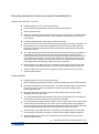
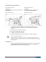
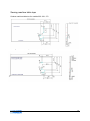
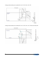
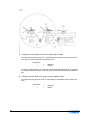
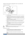
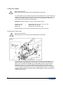
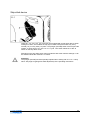
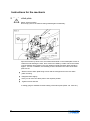
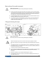
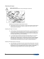
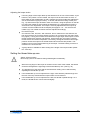
Bedienungsanleitung Operating instructions Manuel d´instructions Instrucciones de servicio 220, 221, 240, 241, 251, 261, 271, 281, 252, 352 Contents Index GB Manufacturer's Declaration…………………………………………………………………………………………………...3 General notes .......................................................................................................................................................... 5 Directives ............................................................................................................................................................ 5 Safety notes ........................................................................................................................................................ 5 Safety symbols .................................................................................................................................................... 6 Items requiring the Operator's special attention .................................................................................................. 6 Operators and specialist staff .............................................................................................................................. 7 Operators ............................................................................................................................................................ 7 Specialist staff ..................................................................................................................................................... 7 Hazard warnings ................................................................................................................................................. 8 Transport, packaging and storage ....................................................................................................................... 8 Installation and initial commissioning .................................................................................................................. 8 Care of the machine ............................................................................................................................................ 8 Disposal of the machine ...................................................................................................................................... 9 Assembly of the machine ...................................................................................................................................... 10 Installation instructions ...................................................................................................................................... 10 Mounting instructions for the mini-motor 46 attachment kit ............................................................................... 11 Classes 221 /241/ 251 / 261 /271 ................................................................................................................. 11 Classes 252/352 ........................................................................................................................................... 11 Automatic frame drop device............................................................................................................................. 12 Accessories: ...................................................................................................................................................... 12 Sewing machine table tops ............................................................................................................................... 13 Operation ............................................................................................................................................................... 15 Threading .......................................................................................................................................................... 15 Machine without thread cutter (Fig. 1) .......................................................................................................... 15 Machine with thread cutter (Fig. 2) ............................................................................................................... 15 Inserting the cloth and sewing ........................................................................................................................... 16 Blind stitch hems on the hem edge ............................................................................................................... 16 Blind stitch hems on the cloth tuck ................................................................................................................ 16 Setting the stitch depth (penetration) ................................................................................................................ 18 Classes 220, 221, 240, 241, 251, 261, 271 .................................................................................................. 18 Classes 252 and 352 .................................................................................................................................... 19 Setting the cloth retainers for classes 251, 261, 271, 281, 252, 352 ................................................................. 21 Setting the helical spring ................................................................................................................................... 21 Fitting the needle............................................................................................................................................... 22 Checking the needle motion ......................................................................................................................... 22 Skip stitch device .............................................................................................................................................. 23 Instructions for the mechanic ................................................................................................................................. 24 Setting the stitch plate ....................................................................................................................................... 24 Basic setting of the needle movement .............................................................................................................. 25 Fitting and checking the looper ......................................................................................................................... 25 Adjusting the looper .......................................................................................................................................... 26 Adjusting the height of the looper ................................................................................................................. 26 Adjusting the lateral position of the looper .................................................................................................... 26 Adjusting the looper stroke ........................................................................................................................... 27 Setting the thread take-up cam ......................................................................................................................... 27 Stitch length adjustment .................................................................................................................................... 28 Plunger (rib shaft) adjustment ........................................................................................................................... 29 Radial position .............................................................................................................................................. 29 Axial position................................................................................................................................................. 29 Play ............................................................................................................................................................... 30 Setting the plunger (rib shaft) timing ............................................................................................................. 30 Plunger (rib shaft) skip stitch timing .............................................................................................................. 30 Feed dog adjustment ........................................................................................................................................ 31 Sewing faults and how to remedy them ............................................................................................................ 32 Sewing tools .......................................................................................................................................................... 33 Technical data ....................................................................................................................................................... 34 2 D Herstellererklärung EG-Konfirmitätserklärung Im Sinne der EG-Maschinenrichtlinie 89/392/EWG Anhang II B Hiermit erklären wir, dass die Bauart der MAIERBlindstichnähmaschine (Nähmaschinenoberteil) Klasse und Seriennr. (siehe Typenschild) zum Einbau in eine Näheinheit oder Nähanlage bestimmt ist und dass ihre Inbetriebnahme solange untersagt ist, bis festgestellt wurde, dass die Näheinheit oder Nähanlage, in die dieses Nähmaschinenoberteil eingebaut werden soll, den Bestimmungen der EG-Maschinenrichtlinie entspricht. Angewendete harmonisierte Normen, insbesondere: EN 292-1, EN 292-2, EN 60204-3-1 Im Sinne der EG-Maschinenrichtlinie 89/392/EWG Anhang II A Hiermit erklären wir, dass die Bauart der Näheinheit bzw. –anlage MAIER-Blindstichnähmaschine Klasse und Seriennr. (siehe Typenschild) folgenden einschlägigen Bestimmungen entspricht: EG-Maschinenrichtlinie 89/392/EWG, zuletzt geändert durch 93/44/EWG, Anhang I Nr. 1 EG-Niederspannungsrichtlinie 73/23/EWG EG-Funktionsstörungsrichtlinie 87/308/EWG Manufacturer´s Declaration EC Conformity Declaration In accordance with the EC Machinery Directive 89/392/EC, Annex II B We hereby declare that the MAIER-Blindstitch Sewing Machine (sewing machine head) Class and Serial No. see rating plate, must be incorporated into a sewing unit or sewing system and that it must not be put into service until the sewing unit or sewing system into which this sewing machine is to be incorporated has been declared in conformity with the provisions of the EC Machinery Directive. Applied harmonised standards, in particular: EN 292-1, EN 292-2, EN 60204-3-1 In accordance with the EC Machinery Directive 89/392/EC, Annex II A We hereby declare that the sewing unit or sewing system MAIER-Blindstitch Sewing Machine Class and Serial No. see rating plate, complete with sewing stand and motor (see rating plate) complies with the following applicable regulations: EC Machinery Directive 89/392/EEC, last amended by 93/44/EEC, Annex I No. 1 EC Low Voltage Directive 73/23/EEC EC Radio Frequency Interference Directive 87/308/EEC Applied harmonised standards, in particular: EN 292-1, EN 292-2, EN 60204-3-1 Declaration du fabricant Declaration de Conformite CE au sens de la directive CE sur les machines 89/392/CEE, annexe II B Nous déclarons que la tête couseuse de la MAIERMachine à coudre à points invisibles (tête couseuse) Classe et no. de série voir plaque est destinée à être incorporée dans une unité ou une installation de couture et que sa mise en service est interdite jusqu’à ce que la conformité de cette unité ou de cette installation de couture aux dispositions de la directive CE sur les machines ait été constatée. Normes appliquées après harmonisation, notament: EN 292-1, EN 292-2, EN 60204-3-1 au sens de la directive CE sur les machines 89/392/CEE, annexe II A Nous déclarons la conformité de l’unité ou l’installation de couture MAIER-Machine à coudre à points invisibles Classe et no. de série voir plaque equipé de table à coudre et moteur (voir plaque) aux prescriptions correspondentes ci-après: directive CE sur les machines 89/392/CEE, dernière actualisation effectué par 93/44/CEE, annexe I no. 1 directive CE sur la basse tension 73/23/CEE directive CE sur l’interference radio 87/308/CEE Normes appliquées après harmonisation, notament: EN 292-1, EN 292-2, EN 60204-3-1 Declaratión del fabricante Declaratión de conformidad de conformidad con la directiva CE sobre máquinas 89/392/CEE, Anexo II B Por la presente declaramos que el tipo de Máquina de puntada invisible MAIER (parte superior de máquina) Clase y número de serie vease placa indicadora está destinada a ser montada en una unidad de costura o instalación de costura, debiendo comprobarse ants de su montaje que la unidad de costura o instalación de costura en la que dicho cabezal debe instalarse, cumple con las disposiciones de la Directiva sobre máquinas CE. Normas armonizadas utilizadas, especialmente: EN 292-1, EN 292-2, EN 60204-3-1 de conformidad con la directiva CE sobre máquinas 89/392/CEE, Anexo II A Por la presente declaramos que el tipo de unidad de costura e instalación de costura de Máquina de puntada invisible MAIER Clase y número de serie vease placa indicadora compl. con mesa de coser y motor (vease placa indicadora) corresponde a las disposiciones siguientes: directiva CE sobre máquinas 89/392/CEE, modificada últimamente por 93/44/CEE, Anexo I No. 1 directiva CE sobre baja tensión 73/23/CEE directiva CE sobre radio interferencia 87/308/CEE Normas armonizadas utilizadas, especialmente: EN 292-1, EN 292-2, EN 60204-3-1 Angewendete harmonisierte Normen, insbesondere: EN 292-1, EN 292-2, EN 60204-3-1 GB F E 3 With this machine, you have acquired a user-friendly, universal and robust highperformance blind stitch sewing machine. All important information relating to working with this machine and the various setting possibilities is provided on the following pages. If you need further information, or have any difficulties whatsoever, please contact your trusted dealer. Of course, apart from this, we - as the manufacturer - are ready to answer your questions at any time, and to help you with any problems you may have. In this case, please write direct to us or telephone us. Maier-Unitas GmbH Maschinenfabrik Postfach 1130 D-73253 Köngen – Germany Tel.: 0 70 24 / 97 02 0 Fax: 0 70 24 / 97 02 10 E-mail: [email protected] Internet: www.maier-unitas.de 4 General notes Directives The machine has been built in accordance with the European regulations stated in the manufacturer's declaration and conformity declaration. In addition to these operating instructions, you must take account of all generally applicable statutory and other regulations and other statutory provisions – including those of the Operator's country - as well as the applicable environmental protection regulations. The locally applicable regulations of the trade association or other supervisory body must always be observed. Safety notes The machine must only be operated in full knowledge of the associated operating instructions and must only be operated by persons with appropriate training. Always read the safety notes and the motor manufacturer's operating instructions before commissioning the machine! The hazard and safety warnings fitted on the machine must be observed! The machine must only be used for the purpose intended and must not be operated without the associated safety devices. All applicable safety regulations must be observed when operating the machine. When sewing (gauge) parts such as needle, stitch plate, for example, are exchanged, during threading, when leaving the workplace and during maintenance work, the machine must be isolated from the mains supply by switching off the main switch or pulling out the mains plug. Daily maintenance work must only be carried out by appropriately trained persons! Repairs and special maintenance work must only be carried out by specialist staff or by appropriately trained persons! Work on electrical equipment must only be carried out by specialist staffs who are qualified for this type of work! Work on live parts and devices is not permitted, except as specified in regulations EN 50110! Conversions or changes to the machine must only be made taking into account all applicable safety regulations! For repairs, only spare parts approved by us must be used! We must expressly point out that spare parts and accessories not supplied by us are also not checked and approved by us. As a result, fitting and/or use of such products can adversely modify the specified design characteristics of the machine. We accept no liability for damage caused by the use of non-original parts. 5 Safety symbols Danger spot! Items requiring special attention. Danger of injury to operators or specialist staff! Attention! Never work without finger guards and protective devices! Switch off main switch before threading, changing needles, cleaning etc. Items requiring the Operator's special attention These operating instructions form part of the machine and must be available for operators at all times. The operating instructions must be read before the initial commissioning. Operators and specialist staff must be given instruction on the machine's protective devices and on safe working methods. The Operator has a duty to ensure that the machine is only operated in perfect condition. The Operator must ensure that no safety devices are removed or disabled. The Operator must ensure that only authorised persons work on the machine. For more information, please enquire at your authorised dealer. 6 Operators and specialist staff Operators Operators are the persons who are responsible for preparing, operating and cleaning the machine, and for troubleshooting in the sewing zone. Operators have a duty to observe the following items: The safety notes specified in the operating instructions must be observed during all work! No method of working must be used that affects the safety of the machine! Close-fitting clothing must be worn. No jewellery, such as chains, necklaces and rings, must be worn! It must be ensured that only authorised persons stay in the danger zone of the machine! Any changes occurring on the machine that affect safety must be notified to the Operator immediately! Specialist staff Specialist staff means persons with electrical/electronic and/or mechanical technical training. They are responsible for lubrication, maintenance, repair and adjustment of the machine. Specialist staff have a duty to observe the following items: The safety notes specified in the operating instructions must be observed during all work! Before starting work and before any adjustment or repair work, the main switch must be switched off and locked off to prevent reclosure! Work on electrical equipment must only be carried out by specialist staff who are qualified for this type of work. No work must be carried out on live parts and devices, except as specified in regulations EN 50110! Protective covers must be refitted after repair and maintenance work! 7 Hazard warnings When the machine is in operation, a 1 m working area must be kept clear in front of and behind the machine, so that unhindered access is possible at any time. No objects must be left lying on the table during setup and adjustment of the machine! The objects could be clamped or thrown out. Risk of injury due to parts flying about. Do not operate the machine without wearing eye protection! Do not operate machines without belt guards! Risk of injury due to the drive belts! The machines are used to produce blind stitches in industrial sewing applications. Any use not by approved by the manufacturer is considered to be incorrect usage! The manufacturer accepts no liability for damage resulting from incorrect usage! Correct use also includes compliance with the operation, maintenance, adjustment and repair measures specified by the manufacturer! Transport, packaging and storage Transport to the dealer / Operator All machines are delivered fully packed. Internal transport The manufacturer does not accept liability for transport within the customer's place of business or to the individual sites of use. It must be ensured that the machines are only transported upright. Disposal of the packaging The packaging of this machine consists of paper, cardboard, polystyrene, wooden pallet and VCE fleece. Correct disposal of the packaging is the customer's responsibility. Storage The machine can be stored when not in use. It must then be protected from dirt, dust and damp. For long-term storage of the machine, the individual components, particularly their sliding surfaces, must be protected against corrosion, e.g. by means of an oil film. Installation and initial commissioning The machine must only be installed and commissioned by specialist staff. All applicable safety regulations must be strictly complied with here! If the machine was delivered without table, the stand and table top provided must safely support the weight of the machine and motor. Adequate rigidity of the pedestal must be ensured, including during sewing operation. Suitable electrical and pneumatic supply connections – as described in the "Technical data" section - must be available at the installation location. In addition, there must be a level, solid base and adequate lighting at the installation location. Care of the machine Switch off the machine! 8 Risk of injury due to the machine being started again inadvertently. Oil holes marked in red are provided on the cover and on the machine body. The machine should be oiled at these points about two or three times per month, One drop of sewing machine oil per oil hole is sufficient. Attention: Make sure that you don't too use too much oil, as this can result in the material becoming soiled. About every two months, the covers on the looper drive and the skip stitch gears should be taken off, any excess oil removed, and the individual lubrication points of the bearings, also marked in red, should be oiled. Also, from time to time, the presser feet under the stitch plate and the plunger shaft (rib shaft) should be lightly oiled. Only use sewing machine oil to lubricate the machine. The time intervals given above relate to single-shift operation. Disposal of the machine Correct disposal of the machine is the customer's responsibility. The materials used on the machine are cast iron, steel, aluminium, brass and various plastics. The electrical equipment is made of plastics and copper. The machine must be disposed of in accordance with the locally applicable environmental protection regulations. It may be necessary to employ a specialist firm for this. Make sure that any parts that have lubricants adhering to them are disposed of separately in accordance with the locally applicable environmental protection regulations. 9 Assembly of the machine Switch off the machine! Risk of injury due to the machine being started again inadvertently. Electrical assembly must only be carried out by a qualified electrician! Installation instructions Fit the stand in accordance with the stand manufacturer's specification. In addition, mount the second pedal. Fit the motor on the table top. Assemble table top and stand. Connect treadle and motor lever. Fit the transmission lever so that the centre hole is located underneath the hole for the chain that is fixed on to the supporting plate. Bolt the top section of the sewing machine on to the table top using two bolts. The fleece must be laid between the top section of the sewing machine and the table top. Connect the support plate chain to the transmission lever. Using the long chain, connect the transmission lever to the second treadle. Fit the V-belt and tension it using the hinged motor bracket. Fit belt guard as shown in Fig. 11. Fit the thread stand. Fitting the finger guard (not on classes 220, 221, 271) It is essential that the finger guard is fitted, to prevent any finger injury when opening the frame (with treadle or stop motor). To do this, remove the ratchet screw, bolt the finger guard onto the table top at a distance of approx 3mm from the supporting plate. Make sure that the supporting plate can move in front of the guard. Refit the ratchet screw. 10 Mounting instructions for the mini-motor 46 attachment kit Classes 221 /241/ 251 / 261 /271 Dismantle the rear cover on the machine body. Remove blanking plug 240236, bolts 221212 and spring 221213. Remove shaft 221204. Refit shim 221204A and push the new shaft into the machine body. The shaft should protrude 10 mm beyond the machine body. Tighten bolt 240205 on the flat, fit set collar 220151. Fit blanking plug 240236, spring 221213 and bolt 221212. Bolt the rear cover back on the machine body. With class 241 and 251 machines, use the hexagon bolt, nut and washer (supplied) as the top fixing bolt. With class 221 machines, replace the fixing bolts for the cover with the long hexagon bolt, spacer, flat washer and nut. The main shaft and gear wheel 221207 must not be turned during the next stages of the assembly. Remove hand-wheel and gear wheel 221226. Push gear wheel 221226 and pulley with pin onto the main shaft; the two gear wheels must not touch one another as you do this. Turn the pulley until the pin engages in the slot in the gear wheel, align the pulley with the faces on the main shaft, push gear wheel and pulley against the machine body, tighten the bolts in the pulley. Mount flange on the shaft, fit motor on the flange, push pulley onto the motor shaft. Fit belt, align motor pulley and tighten, tension belt and tighten flange fixing bolts. Adjust hexagon bolt on the cover to a distance of 0.5 mm from the motor, fit belt guard and hand-wheel. Classes 252/352 Dismantle the rear cover on the machine body. Remove blanking plug 240236, slacken set collar 240203 and remove shaft 221204. Push the new shaft into the machine body. The shaft should protrude 10 mm beyond the machine body. Tighten bolt 240205 on the flat, fit set collar 240203 and fit blanking plug 241236. Bolt rear cover onto the machine body; use the hexagon bolt, nut and washer (supplied) as the top fixing bolt. The main shaft and gear wheel 221207 must not be turned during the next stages of the assembly. Remove hand-wheel and gear wheel 221226. Push gear wheel 221226 and pulley with pin onto the main shaft; the two gear wheels must not touch one another as you do this. Turn the pulley until the pin engages in the slot in the gear wheel, align the pulley with the faces on the main shaft, push gear wheel and pulley against the machine body, tighten the bolts in the pulley. Mount flange on the shaft, fit motor on the flange, push pulley onto the motor shaft. Fit belt, align motor pulley and tighten, tension belt and tighten flange fixing bolts. Adjust hexagon bolt on the cover to a distance of 0.5 mm from the motor, fit belt guard and hand-wheel. (see spare parts list for numbers given here) 11 Automatic frame drop device Frame drop device PFL-M Frame drop device PFL-P Consisting of: solenoid with Bowden cable, mounting bracket and deflection pulley. Consisting of: compressed air cylinder, regulating valve, solenoid valve and Bowden cable. Order reference: PFL-M Order reference: PFL-P The frame drop devices PFL-M and PFL-P can be obtained directly from us. The stop motors and frame drop devices must be switched to give the following sequence: Positioning (needle in extreme left position) Cutting with treadle position fully down Dropping / opening of the table (frame) Intermediate dropping without cutting is possible at the treadle mid-position. Attention - operators please note: The table (frame) is under strong spring tension. So always make sure that your fingers are outside the danger zone when you release the treadle after the cutting and dropping process. Accessories: Thread stand, treadle with transmission linkage or knee-lift lever, chains, hooks, 2-part belt guard plate, finger guard (not with classes 220, 221, 271), oiler, screwdriver, open-ended spanner, Allen key, cover, spare parts list. 12 Sewing machine table tops Sewing machine table top for models 220, 221, 271 Sewing machine table top for models 220, 221, 271 with sub-class 46 13 Sewing machine table top for models 240, 241, 251, 252, 261, 281, 352 Sewing machine table top for models 240, 241, 251, 252, 261, 281, 352 with sub-class 46/2 14 Operation Threading Switch off the machine! Risk of injury due to the machine being started again inadvertently. Machine without thread cutter (Fig. 1) The thread is run over the thread stand through the thread guide A, the rear thread eyelet, between the thread tensioning discs C (not round the pin), through the front thread eyelets D (right-hand hole) and through the hole on the needle claw E. The needle is threaded upwards from below. Move the needle lever to the extreme left position for threading. The thread eyelet D offers three possibilities for threading. In conjunction with the thread take-up cam, the tension of the sewn thread loop can be influenced in this way. Normally the thread is run through the right-hand hole. However, running the thread through the left-hand hole gives a slacker thread loop. The effect can be increased further by turning the thread take-up cam (set collar). Adjust the thread tension C as slack as possible. Excessive thread tension can cause marks (thread pulls) on the outside of the material. Please use the correct thread quality e.g. 120/single, 120/double, 200/double. Machine with thread cutter (Fig. 2) When using our thread cutter (Fig. 2), the machine is threaded in the same way as shown in Fig. 1. In addition, however, the thread is also run through eyelet A and the groove of the thread clamp B, through the hole in the base plate to the front thread eyelet. Push back the flexible cap B to do this. As a result, the thread is clamped during the cutting operation. There must be approx. 0.2 mm play between the nuts and the angle flange, so that the connection pin D together with the brake cap B can be turned or moved easily. Also, connecting rod E must not bind. 15 Inserting the cloth and sewing The needle must be in its extreme left-hand position when inserting the cloth. Press down on the treadle or knee-lift lever, then insert the cloth so that the hem fold is positioned on the right-hand side and is far enough under the feed dog for the feed dog to grip it. Blind stitch hems on the hem edge Usually, the blind stitch hems are sewn on the hem edge, as shown in Fig. 5. The function of the guide rule B here is to guide the cloth. The edge of the hem C slides along the guide rule. The guide rule B is adjustable. It is moved to the left for thick cloth and to the right for thin cloth. Only tighten bolt D (Fig. 6) slightly. The guide rule is correctly adjusted when the seam coincides exactly with the hem edge C. During sewing, you must always ensure that the hem edge C slides along the guide rule B. Only then can it be guaranteed that the seam is exactly on the hem edge. Blind stitch hems on the cloth tuck If the blind seam must be sewn on the hem tuck, the front guide rule E (Fig. 6) is used instead of the guide rule integrated in the stitch plate (Fig. 5). It is fitted with bolt D (Fig. 6). It is essential that guide rule B is then removed. The front guide rule E then acts as a guidance aid for the hem edge C and so ensures a uniform distance to the seam F. Attention! The front guide rule E can also be used to advantage for hemming at the hem edge of very thick material. Classes 252, 352 work exclusively with the front guide rule. When sewing is complete, stop the machine in such a position - if necessary turn the hand-wheel further by hand - that the needle is in the farthest left position, press down the treadle or knee-lift lever, then cut off the thread loop with scissors or pull the cloth back with a short tug so that the thread tears off over the looper and so knots the seam. The last stitch must be located inside the cloth, as a blind stitch sewing machine does not loop. 16 When using a stop motor with frame drop device and thread cutter, then simply by stepping back off the treadle, the needle is automatically positioned, the thread cut off and the frame opened for removal of the material. If thread pulls are visible on the outside of the cloth after sewing, or if the seam is too loose at the hem edge, the thread tension must be set slacker or tighter accordingly. With delicate materials (jersey fabrics, etc.), sew with the lowest possible thread tension (possibly use a finer needle size 70 or 60). 17 Setting the stitch depth (penetration) Classes 220, 221, 240, 241, 251, 261, 271 Adjusting screw A for setting the stitch depth is located under the frame plate. To check the stitch depth, turn the hand-wheel until the needle point is positioned directly above the plunger (rib shaft) B. When correctly set, the needle should just pass over the plunger (rib shaft) B without touching it. When checking the adjustment, make sure that you do not operate the treadle or knee-lift lever, as otherwise the adjustment will be incorrect (with the automatic presser foot device, the associated Bowden cable must be slack). If the needle passes too high over the plunger (rib shaft) B, as shown in C, turn the stitch depth adjusting screw anticlockwise. However, if the needle strikes the plunger (rib shaft) B, as shown in D, turn the adjusting screw clockwise. Penetration Low number High number = = shallower deeper Both the adjusting screw A and the numbers are clearly visible through the small opening in the frame or swing-out table. If some stitches are missed (shallow penetration) during sewing, adjust the machine in accordance with C. However, if some stitches appear on the outside of the cloth, adjust the machine in accordance with D. On machines with spring-loaded plunger/rib shaft (classes 251/261/271), accurate adjustment of the cloth retainers is very important. See page 21 of the operating instructions for more on this. 18 Classes 252 and 352 With the above machine classes (double blind stitch), the cloth is inserted folded in an "S" shape (see Fig. 4). In this case, the distance from the seam to the hem edges can be any value required. All other essential information on inserting the cloth is described on page 16. For accurate adjustment of the stitch depths of both plungers/rib shafts, it is particularly important to follow the correct sequence: Setting the cloth guide Depending on the cloth thickness, the cloth guide at the front of the stitch plate must be adjusted such that the folded hem edge is positioned exactly between the two plungers/rib shafts. Reason: the setting of the right-hand plunger/rib shaft is influenced as a result. If the hem edge is too far to the left, it will be pierced too deeply by the needle. If, on the other hand, it is too far to the right, it will not be caught by the needle. Two folders and edge guides are provided to make it easier to guide the cloth. -26: the fabric hem is automatically folded into an "S" shape. Seam inset from the edge of the hem can be any value. -28: the hem edge is automatically folded into an "S" shape. Seam inset from the edge of the hem is approx. 5 mm. 19 Setting the stitch depth of the left-hand plunger/rib shaft The left-hand plunger/rib shaft is responsible for penetration of the outside of the hem and so must be adjusted with particular care. Penetration + = = shallower deeper For design-related reasons, the right-hand plunger/rib shaft depends on the setting of the left-hand plunger/rib shaft. That is why the left-hand plunger/rib shaft is adjusted first. Setting the stitch depth of the right-hand plunger/rib shaft The right-hand plunger/rib shaft is responsible for penetration of the inside of the hem. Penetration + 20 = = shallower deeper Setting the cloth retainers for classes 251, 261, 271, 281, 252, 352 (lowering over cross seams) For setting the cloth retainers, the cloth is inserted in the machine as for sewing (not on the cross seam). Cloth retainer A (the left-hand cloth retainer on classes 251,261,271 and 252/352) is adjusted with the knurled screw B such that - with a single layer of cloth (when the needle pierces the cloth) – the shoe can still move slightly if you press your finger on the knurled screw. The right-hand cloth retainer on class 252/352 is adjusted in the same way, but with a triple layer of cloth (folded in an "S" shape). When sewing over the cross seam, the cloth retainers press the plunger (rib shaft) down, so that, with the correct setting, only the cloth tuck of the cross seam is pierced. If the outside cloth layer is pierced in the area of the cross seam (thread pulls on the outside of the hem), the cloth retainer clearance must be reduced (turn the knurled screw clockwise). If, on the other hand, the top layer of cloth (cloth tuck) is not pierced, the cloth retainer clearance must be increased (turn knurled screw anticlockwise). During sewing, the cloth retainers must move up and down alternately. Important: The plunger and cloth retainer are interdependent during adjustment, so the cloth retainer may need readjusting after adjusting the plunger (rib shaft). Setting the helical spring The plunger (rib shaft) must spring downwards when sewing over cross seams. The strength of the spring force can be adjusted with the knurled nut. Hard cloths need a harder setting, softer cloths need a softer setting. Fig. 4 = helical spring for plunger (rib shaft) or left-hand plunger on classes 252/352 Fig. 4 = helical spring for plunger (rib shaft) or right-hand plunger on classes 252/352 21 Fitting the needle Switch off the machine! Risk of injury due to the machine being started again inadvertently. To fit the needle, turn the machine by hand until the needle lever is in the extreme left position. Now slacken the fixing screw a few turns, take out the old needle, fit the new needle from the side and push it right up to the stop. Then tighten the fixing screw. The needle centres itself as it has a flat shank. Important: make sure that you use the correct needle system! System 251 EU System 251 LG System 251 = = = Classes 220, 221, 240, 241, 251, 271, 352 Classes 251-25, 252, 261 Classes 221-19/2 and 221-19/4 Normal needle size 80, size 70 or 60 for thin cloth, size 90 for thick cloth. Checking the needle motion Switch off the machine! Risk of injury due to the machine being started again inadvertently. The accuracy of the needle motion must be checked each time before fitting a new needle and before the starting up of the machine. To do this, turn the machine by hand. Here, the needle should slide on the needle plate A with no clearance until stitching the cloth, but it must not be lifted by it either. When the needle is at the farthest right position B, the play between needle and stitch plate should be approx. 1/10 mm. If these requirements are not met, try fitting another needle. If no needle is suitable, check that you are using the correct needle system. It may be necessary to readjust the stitch plate. 22 Skip stitch device Class 221, 241, 251, 261, 271 machines are equipped with a skip stitch device. When sewing thin cloths, this enables the top layer of cloth to be pierced with only every second (1:2) or every third (1:3) stitch. The plunger (rib shaft) either moves beyond the needle, or stops short of it, in this 1:2 or 1:3 cycle. Turn switch handle A to "ON" to switch on the skip stitch mode. Switching on the skip stitch drive does not interfere with other machine settings. It can be switched whilst the machine is in motion. Attention! The plunger (rib shaft) must be specially adjusted when sewing with a 1:2 or 1:3 skip stitch. See page 29 (plunger/rib shaft adjustment) of the operating instructions. 23 Instructions for the mechanic Setting the stitch plate Switch off the machine! Risk of injury due to the machine being started again inadvertently. Spin the machine by hand. Here, the needle should slide on the needle plate A with no clearance until stitching the cloth, but it must not be lifted by it either. When the needle is at the farthest right position B, the play between needle and stitch plate should be approx. 1/10 mm. In addition, the feed dog must be located in the centre of the stitch plate cut-out. Slacken the two stitch plate fixing screws and the hexagon bolt on the rear stitch plate mounting. Retighten them slightly. Now you can move the stitch plate to the required position. Tighten screws and bolt. A setting gauge is available for basic setting of the stitch plate (Order. No. V241101). 24 Basic setting of the needle movement Switch off the machine! Risk of injury due to the machine being started again inadvertently. Position the needle at the right-hand dead centre position by turning the hand-wheel. The needle point must now be 2 mm (0.7 mm on class 252 and 1.0 mm on class 352) away from the right-hand stitch plate edge. Adjustment is by slackening and turning the needle lever. Hold the hand-wheel firmly as you do this. The left-hand dead centre point of the needle must be such that the needle is free for threading. Adjustment is by turning eccentric cam D. The needle movement can be adjusted by turning eccentric cam D after slackening screw E. The position of the needle may have to be corrected by slackening the hexagon bolt on the needle lever. Fitting and checking the looper Switch off the machine! Risk of injury due to the machine being started again inadvertently. Slacken the looper fixing screw A and remove the looper by pulling it forward. Place the new looper on the looper holder B and push it backwards until it hits screw A. Then tighten the screw. If our original looper is used, no readjustment of the machine is necessary. Even so, you should spin the machine by hand to establish whether the movement of the looper is correct. To do this, turn the hand-wheel backwards carefully. As you do this, the looper must not touch either pin C or the needle, or even the stitch plate at point D. It must stroke the needle scarf exactly at point E, but without touching it. Normally, the distance to the needle should be approx. 0.05 mm. The long finger of the looper must pick up the thread immediately behind the eye of the needle. See Fig. 18. 25 Adjusting the looper Switch off the machine! Risk of injury due to the machine being started again inadvertently. Basically, the following rule must be borne in mind: When adjusting the eccentric cam G (Fig. 18), the looper is raised or lowered at both points E and L. By turning looper holder B, the path of the looper is raised on one side and lowered on the other. Adjusting the height of the looper If the long finger of the looper touches the needle at point L or the stitch plate at point E or D, the looper must be set slightly higher. To do this, slacken the two locking screws F (Fig. 18) on the eccentric cam G. If the looper touches the needle, turn the eccentric cam G upwards in a clockwise direction. If the looper is too far away from the needle, adjust the eccentric cam anticlockwise. If, on the other hand, the looper touches the stitch plate at point E or D, and at the other side the needle touches the short finger of the looper at point L, then an adjustment of the eccentric cam G is not sufficient. This fault can only be rectified by turning the looper holder B slightly. To do this, slacken screws H and then retighten them afterwards. This will prevent any contact by the small looper finger at point L and will raise the looper at points E and D, so that it no longer touches there. Adjusting the lateral position of the looper If the small finger of the looper hits pin M or hits the stitch plate at point N, check first whether the feed dog lever link O is firmly tightened on to the set collar P, so that the feed dog lever link has no play. Adjust the set collar if necessary. If the looper still hits at points M or N, it can be adjusted to the left or right if required, by slackening screws F and moving the entire eccentric cam G to the right or to the left. 26 Adjusting the looper stroke If the long finger of the looper takes up the thread too far in front of the needle, or just behind it, as it passes over the needle, the looper must be set forward or back, so that it takes up the thread earlier or later. Adjusting the looper holder also adjusts the size of the thread loop (looper stroke). To do this, slacken the locking screws (see Fig. 17) and set the looper forward or back one full turn, using the spanner on the flat K of the looper holder B. After making the adjustment, it is essential that screws H and locknut I are retightened. The looper is correctly adjusted when the looper tip crosses over the needle scarf at its deepest point (approx. 1.5 – 2.0 mm from the needle eye). The needle movement must be adjusted accordingly. Eccentric link joint On class 221-19/2, 252, 261, 352 machines, and on machines in sub-class 25, the link joint is fixed to the eccentric head by means of an eccentric bolt (see spare parts list, page 6). Turning this eccentric bolt causes the longer finger of the looper to come further forward at its extreme right position. At the same time, the looper is shifted further back at its extreme left position. Conversely, setting back at the extreme right position causes the looper to be shifted forward at the extreme left position. This enables even more accurate positioning of the looper. The basic setting ex-works is marked on the eccentric bolt. A gauge block is available for basic setting of the length of the looper holder (Order. No. V241103). Setting the thread take-up cam Switch off the machine! Risk of injury due to the machine being started again inadvertently. When the long finger of the looper is located over the scarf of the needle, the thread should lie flat against the right edge of the thread take-up cam. (see Fig. 18) The appearance of the seam and the thread tension setting can be influenced by adjusting the thread take-up cam. If the thread take-up cam is adjusted to the right, more thread is pulled through and the size of the loop formed with the looper stroke can be reduced. If the thread take-up cam is adjusted to the left, less thread is pulled through. As a result, the thread tension can be reduced slightly. 27 Stitch length adjustment Switch off the machine! Risk of injury due to the machine being started again inadvertently. Remove cover and slacken screw A. The adjustment eccentric B can now be adjusted to the required stitch length by turning it using the holes. A zero mark is provided on the eccentric head C. This serves as a reference point. The number appearing opposite the zero mark is the stitch length in millimetres. Higher number – longer stitch length, lower number = shorter stitch length. When changing the stitch length, bear in mind that the feed dog changes too, and on class 220, the plunger (rib shaft) also changes. So you must recheck the feed dog setting, see page 30 of the operating instructions. 28 Plunger (rib shaft) adjustment Switch off the machine! Risk of injury due to the machine being started again inadvertently. Radial position Correct adjustment of the needle is prerequisite for adjusting the plunger (rib shaft). When correctly adjusted, the plunger (rib shaft) should stop with its tip A approx. 2 – 3 mm in front of the needle as the needle point passes over it, If it stops too far in front of, or behind the needle, an adjustment must be made. To do this, slacken screw B. Using an open-ended spanner on the flats provided on the plunger shaft, the plunger (rib shaft) can then be adjusted backwards or forwards. Retighten screw B firmly afterwards. Axial position The same requirement holds for all classes, i.e. that the plunger (rib shaft) stops exactly in the middle under the cloth retainer. If this is not the case, it can be adjusted as follows: Classes 220, 221, 271: Align the plunger (rib shaft) accurately by adjusting the pivot screws. See spare parts list, page 4, items 19 and 20. Classes 240, 241, 251, 261: Align the plunger (rib shaft) by adjusting the set collar. See spare parts list, page 4, item 25. Classes 252,352 Left-hand plunger (rib shaft): Align the plunger (rib shaft) by adjusting the set collar. See spare parts list, page 4, item 35 Right-hand plunger (rib shaft): Align the plunger (rib shaft) accurately by adjusting the pivot screws. See spare parts list, page 4, item 73. 29 Play Once the alignment is complete, make sure that the plunger (rib shaft) has no axial play. Any play can be corrected by a tighter setting of the set collar or the pivot screws on the plunger shaft. If the plunger (rib shaft) has any radial play, this can be remedied by readjustment. On classes 221, 271 and on the right-hand plunger (rib shaft) on classes 252, 352, this is carried out by adjusting the pivot screws. (Classes 221, 271, see spare parts list, page 10, item 35, classes 252, 352, see spare parts list, page 4, item 73). On classes 240, 241, 250, 251, 261, this is carried out by adjusting the two set collars on the plunger shaft. Make sure that the machine does not become stiff. Please remember to the lock the cone screw again with the appropriate nut. Setting the plunger (rib shaft) timing To ensure accurate penetration, the plunger (rib shaft) must stop when the needle passes over it. The return movement must only start when the needle eye crosses the plunger tip on the forward movement of the needle. This can be checked by turning the hand-wheel slowly. If the plunger (rib shaft) moves earlier or later, the following adjustment is necessary: Slacken screws D at the back of the machine (Fig. 22), then turn the hand-wheel until the needle point is positioned in the middle of the stitch plate cut-out. Now turn the eccentric E forwards or backwards until the plunger (rib shaft) is at its rear reversing position. During the adjustment, hold the needle stationary by means of the handwheel. When correctly adjusted, retighten screws D firmly. Afterwards, the plunger (rib shaft) adjustment should be checked again as described above. Plunger (rib shaft) skip stitch timing When sewing in skip stitch mode, the plunger (rib shaft) must perform one short stroke and one long stroke alternately. The skip stitch eccentric must be adjusted for this. (for part numbers, see spare parts list, page 10) Turn the hand-wheel until the plunger (rib shaft) is in its rearmost position. Remove the hand-wheel and gear wheel 221226. Turn gear wheel 221227 until the plunger (rib shaft) is in its rearmost position. Fit the hand-wheel with gear wheel 221226. When doing so, make sure that the main shaft and gear wheel 221227 do not turn. 30 Feed dog adjustment Switch off the machine! Risk of injury due to the machine being started again inadvertently. The feed dog must be adjusted such that – in its lowest position – it projects approx. 2 mm (at least tooth depth) beyond the underside of the stitch plate. In addition, it should be placed as far forward as possible in the stitch plate cut-out. If necessary, the feed dog can be adjusted in its elongated hole by slackening the fixing screws. Please make sure that these screws are firmly retightened afterwards. 31 Sewing faults and how to remedy them Fault Cause Remedy Thread tears Thread tension too tight Needle worn out Looper wrongly adjusted Needle stroke wrongly adjusted Sharp edge in looper, stitch plate or feed dog Slacken thread tension Change needle, see page 16 see page 25 see page 16 Polish the part Needle breaks Needle not fitted correctly Wrong needle system Looper wrongly adjusted Plunger (rib shaft) timing incorrect see page 16 Check needle system, see page 16 see page 25 Adjust plunger (rib shaft), see page 28 Missing stitches Needle bent or blunt Change needle, see page 16 Looper wrongly adjusted Wrong needle system Needle stroke wrongly adjusted Needle support plates worn out Stitch plate wrongly adjusted Stitch plate set incorrectly Thread take-up cam wrongly adjusted see page 25 Needle system, see page 16 see page 16 Replace needle support plates Check, adjust if necessary, see page 23 Set stitch plate, see page 23 Correct adjustment, see page 26 Needle bent or blunt Plunger (rib shaft) timing incorrect Stitch plate set incorrectly Bearing play in plunger shaft or plunger lever Plunger (rib shaft) not exactly in the middle under cloth retainer Transport problems in the area of the cross seam can be caused due to the guide rules. Change needle, see page 16 Adjust plunger (rib shaft), see page 28 Set stitch plate, see page 23 Adjust plunger (rib shaft), see page 28 Penetration Miscellaneous 32 Adjust plunger (rib shaft), see page 28 Only use one guide rule, or replace with another guide rule. Sewing tools The machines are equipped with special sewing tools for different purposes. The tools are also available separately: Tool Order No. Feed dog 220145 220145 F 220145 G 220145 PY 220145 GU Feed dog 252145 252145 F 252145 G 252145 PY 252145 GU Feed dog 352145 352145 F 352145 M 352145 PY 352145 GU Plunger (rib shaft) 250167 ST Plunger (rib shaft) 240167 ST Cloth retainer 240114 240114-31 240114-10 Cloth retainer 250114 250114-31 250114-10 Description Suitable for classes 220, 221, 240, 241, 251, 271, 281 Normal serration Fine serration Coarse serration Pyramidal serration Rubber coating Suitable for class 252 Normal serration Fine serration Coarse serration Pyramidal serration Rubber coating Suitable for class 352 Normal serration Fine serration Medium serration Pyramidal serration Rubber coating Suitable for class 251 5 mm wide, for coarse-meshed knitwear Suitable for classes 240, 241 5 mm wide, round Suitable for classes 221, 240, 241 Normal slot Narrow slot Wide slot Suitable for classes 251, 261 Normal slot Narrow slot Wide slot In addition, a useful aid is available for exchanging the table spring, the lever for mounting the table spring, Order No. V241102 33 Technical data Number of stitches/min up to Length of stitch Hand-wheel diameter (effective) V-belt width Motor power Motor speed Motor shaft V-belt pulley (effective diameter) Needle system Noise Class 220, 221, 240, 241, 251, 271 3000 3-8 mm 63 mm Class 252 Class 352 Class 261 2500 3-8 mm 63 mm 2500 3-8 mm 63 mm 2300 3-8 mm 63 mm Class 221-19/2, 22119/4 2000 2-8 mm 63 mm 10 mm 0.25 kW 1400 rpm 125 mm 10 mm 0.25 kW 1400 rpm 106 mm 10 mm 0.25 kW 1400 rpm 106 mm 10 mm 0.25 kW 1400 rpm 100 mm 10 mm 0.25 kW 1400 rpm 90 mm System 251 EU 75 dbA System 251 LG 75 dbA System 251 EU 75 dbA System 251 LG 75 dbA System 251 75 dbA If a very accurate stitch penetration is required, it is advisable to run the machine at reduced speed and to select a V-belt pulley approx. 20% smaller. approx. 2500 rpm with a 106 mm diameter motor shaft V-belt pulley approx. 2300 rpm with a 100 mm diameter motor shaft V-belt pulley approx. 1800 rpm with an 86 mm diameter motor shaft V-belt pulley. 34