1
CodeLoader 4 Operating
Instructions
Version 4.1.13
Last Updated:
8/25/2008
Installation............................................................................................................................................................3
Installing the Main CodeLoader File............................................................................................................... 3
Components of the CodeLoader 4 Program.................................................................................................... 5
Adding a New Part to the CodeLoader Program............................................................................................ 6
Using the CodeLoader 4 Software...........................................................................................................................8
Selecting the Device Type ............................................................................................................................. 8
Port Setup Tab.............................................................................................................................................. 9
Port Setup Tab (USB Operation) .................................................................................................................. 10
Bits and Pins Tab ........................................................................................................................................ 10
PLL Tabs ..................................................................................................................................................... 11
Registers Tab.............................................................................................................................................. 13
Burst Mode Tab.......................................................................................................................................... 13
Loading the Data to the PLL......................................................................................................................... 14
Additional Bells and Whistles ...................................................................................................................... 15
ACTIVE X CODELOADER 4 FOR AUTOMATED TEST AND MEASUREMENT ..................................................................16
What is Active X CodeLoader 4?........................................................................................................................16
Registering and Using the Active X CodeLoader 4 Version ...................................................................................16
Using the Active X CodeLoader 4.......................................................................................................................16
Active X CodeLoader 4 Commands ....................................................................................................................17
Sample Application of the Active X CodeLoader 4...............................................................................................18
TROUBLESHOOTING CODELOADER 4 PROBLEMS ...................................................................................................20
Investigate Potential CodeLoader 4 Issues .........................................................................................................20
Parallel Port Issues...........................................................................................................................................21
Investigate Potential Hardware Issues ...............................................................................................................21
2
Installation Installing the Main CodeLoader File After the setup file is launched, the following menus appear: Click Next to continue the setup. One can press Cancel at any time of the setup to abort. This selects the default location to install this program. It is generally recommended to keep the default location so that when updated versions of the installation file are run, there is no confusion about which CodeLoader is running. If a CodeLoader already exists in this directory, then the install program will overwrite it. This will create the icon on the start menu. 3
This will create an shortcut icon on the desktop. Press the Install button to install the program. A restart is sometimes necessary in order to complete the installation. If the computer is not restarted after CodeLoader 4 is installed, then program may not send the programming information to the part, although it will function normally in all other ways. Be aware that administrative access is required for proper installation and for access to the parallel port. 4
Components of the CodeLoader 4 Program The install program installs the following : 1. Main Executable This is the CodeLoader 4 executable file. The name is different depending on which windows platform it is running on. For Windows 95/98, the file is named “codeldr95.exe” and for NT/2000/ME/XP, it is “codeldrNT.exe”. The current version of the executable file can be found by choosing Help ‐‐> About from the menu. 2. Active X Executable This Active X executable file can be called from other programs. It is automatically installed when the main executable file is installed, and is only necessary for automated test and measurement applications, described in Part 2 of this document. It is called “codeldr95x.exe” for windows 95/98 and “codeldrNTx.exe” for windows NT/2000/ME/XP. 3. Menu Initialization File This is a text file which contains the parts that CodeLoader 4 can run. It can be easily modified by the user in order to add or subtract parts. If a part is on this list, there also needs to be a part‐specific initialization file as well. This file is windows independent and is called “codeldr.ini” 4. Part‐Specific Initialization Files These files contain part specific information for each part including the counter sizes, prescalers, and pins. These files are windows independent and are of the form LMXxxxx.ini. For instance, the part‐specific initialization file for the LMX2330 is “lmx2330.ini”. Each part‐specific initialization file has a version. This can be found by choosing Help ‐‐‐> About from the menu. 5
Adding a New Part to the CodeLoader Program Recall that the CodeLoader file has part specific initialization files. The version of CodeLoader that is on the web and widely distributed will not have parts if they are not released yet. If you are evaluating a part like this and were just given a *.ini file, this procedure shows how to add it to the menu on CodeLoader. As a matter of protocol, parts that are not fully released are included under the “ENGINEERING” section of the menu. Step 1: Find the directory that CodeLoader 4 is in The default directory is Program Files/National Semiconductor/CodeLoader 4 Step 2: Detach the *.ini File Detach the *.ini file to this default directory. Step 3: Edit the codeldr.ini file Now open the codeldr.ini file in this default directory. It should look something like this. Note that sometimes windows can hide file extensions. The next time the Codeloader application is launched, the new part should appear on the menu and be able to select from the dropdown menu. 2. 6
This shows the codeldr.ini file Double click it to get to the next step. This shows the top of the file. Scroll down to the bottom and it should look something like the picture below. Depending on which parts were used, this could be different. Although it can be added anywhere, it is general practice to add it to the ENGINEERING section. Be sure to update the count and add the part. The name must be exactly the same as the ini file name, minus the “ini” part. So the LMX2364.ini file would imply to put “LMX2364” here. 7
Using the CodeLoader 4 Software There are three ways to start this program: 1. Desktop Icon 2. Start Bar Icon 3. Windows Explorer Selecting the Device Type After the program is run, go to the Select Device menu and Select the desired device. After the device is selected, the CodeLoader 4 will take a few moments to configure to the specific settings for that device. Note that the specific devices that are displayed on the menu are specified in the codeldr.ini file. If the desired device is not on this list, then it is necessary to replace the codeldr.ini file with the correct version. 8
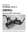
Port Setup Tab The code loader provides the user with the capability of customizing the port configuration and various program signals from the parallel port of the user’s computer. The port setup is board specific and specific to each device as well. If the port setup is incorrect, it is likely the part will not program correctly. In addition to the clock, data, Latch Enable (LE), and Chip Enable (CE) pins, there may be additional pins used to output a high or low voltage for various pins on a part. The most common use of these is for the Chip Enable pins on various wireless products. There is also the trigger pin, which can be used to trigger the oscilloscope if one wants to observe the bits being sent to the part. The numbers for the port setup correlate to the specific pin on the DB25 connector that the signal is sent to. Attached to the computer’s parallel port is a ribbon cable with a 10‐pin header. The interactive port diagram (below) gives the relationship between the port setup, cable, and 10 pin header. Port Setup Name 1 2 4 8 16 32 64 128 C1 C2 N/A Port Setup Column 1 2 3 4 5 6 7 8 9 10 N/A DB25 Connector Pin 10‐Pin Header Pin DB2 DB3 DB4 DB5 DB6 DB7 DB8 DB9 DB1 DB25 18 ( Ground ) 1 2 4 3 5 6 7 8 10 Not Used 9 9
Computer Parallel Port ( As Seen from Back of PC ) 1
2
14
4
3
15
16
6
5
17
18
19
9
8
1
7
20
21
10
22
12 13
11
23
24
25
2
4
6
8
10
1
3
5
7
9
Ribbon Cable 10‐Pin Header ( Top View ) Port Setup Tab (USB Operation) An additional feature of CodeLoader 4 is that it offers support for a custom USB to parallel port board. This board is currently in the prototyping stages and will hopefully be available for purchase soon. To use this option, ensure that the USB radio button is enabled on the Port setup tab. A known issue with this board that is currently being resolved is that it does not communicate properly with pin 10 on the 10‐pin header.
Bits and Pins Tab Two example settings for the Bits/Pins are shown below. Refer to the datasheet for the functions of each bits and pins. For those functions that have a box to the left‐hand side of them, an X in the box indicates high voltage and an unchecked box indicates low voltage. For some of the bits, a more detailed description is available by right mouse clicking on the description. The proper configuration for this board is shown below: 10
2
PLL Tabs Depending on the number of PLLs included in each device, there will be a varying number of tabs. For instance, the LMX2330 has 2 PLL tabs. For each tab, the user needs to enter the Reference Oscillator frequency, the VCO frequency, and the Phase Detector Frequency. It is also possible to enter some counter values as well. The phase detector polarity, charge pump gain, and charge pump state can be changed by clicking on the appropriate box. If the writing in the box is grayed, then these states can not be toggled. A sample setting is shown below: 11
12
Registers Tab The registers tab shows the bits CodeLoader 4 is sending to the device. The names of all the data registers are displayed. For each register, the bit on the right hand side is the MSB and is sent first, while the bit on the left hand side is the LSB and is sent last. When the Load PLL command is used, all data in each register is sent. Although the bits on this screen are calculated from the Bits/Pins tab and PLL tabs, the user can modify them. If a bit is selected, the register, number, and hexadecimal value of the register are displayed. Burst Mode Tab The burst mode allows the user to toggle between various values. A typical application of this is when the user wants to measure the lock time of the PLL. However, any combination of bits and pins can be toggled. The register values can not be changed on the burst mode tab, but instead are changed on the PLL or Bit/Pins Tab. To know what bits corresponding to what functions are on what registers, refer to the datasheet. For instance, if the user wanted to cause the RF PLL to toggle between 2 different frequencies, he would need to first go to the RF PLL tab and set things to the first desired frequency. Then they would return to the Burst Mode tab and choose the register holding the RF N counter information, which would be the RF_N register. Then a delay would be inserted. The delay is just processor cycles, and is therefore processor dependent. The user then goes back to the RF PLL tab and sets the other desired frequency, returns to burst mode, and inserts the delay. 13
Loading the Data to the PLL Although this step is pretty trivial, it is still important. To load the data to the PLL, the user needs to go to the Keyboard Controls Menu and select Load PLL. This will load all of the data to all of the registers. After this step is done once, it is not necessary to do it again because when something is changed, CodeLoader 4 automatically sends out register corresponding to the changed function. Note that after any value or bit is changed, then that register information is automatically sent, however, it is still necessary to use the Load PLL command one time. For instance, changing the VCO frequency programs the N counter information, but not the R counter information. 14
Additional Bells and Whistles Since computer monitors produce considerable noise spikes, it is often necessary to turn them off. These keyboard controls allow the user to control the PLL with the computer monitor off. The F2 and F1 function keys are also useful to hand tune the PLL. There is also a prescaler check which can perform a dual and quadruple modulus prescaler check. If the divide ratio is legal, then the numbers are displayed in green, otherwise, they are red. Note that CodeLoader 4 does not prevent the user from programming illegal divide ratios. Also realize that this prescaler check is not part‐specific. For the majority of the PLLs, this does not matter, but there are some exceptions, which currently include all the fractional parts that require that A +2 B, as opposed to A B. The prescaler check is based on the prescaler value that is displayed on the screen. 15
ACTIVE X CODELOADER 4 FOR AUTOMATED TEST AND MEASUREMENT What is Active X CodeLoader 4? Active X is a standard referring to modules of code that can be accessed from other programs. This allows programs to be more modular and makes it easier to reuse code. CodeLoader 4 95/NT/98 versions of the program allow the user to access this code so that other programs can use the CodeLoader 4. This is useful in applications where one would want to use CodeLoader 4 for automated test measurement. Registering and Using the Active X CodeLoader 4 Version Although a trivial step, it is important nevertheless. To register the program, double click on the Active X version of the program. It is only necessary to register the program once. For Windows 95/98, the filename is Codeldr95x.exe and for Windows NT/2000/ME/XP it is CodeldrNT.exe. There is no Active X version for Windows 3.1, since this platform does not support Active X. Usually, when the file is double clicked, an hourglass will appear for a fraction of a second and then go away. Using the Active X CodeLoader 4 Once the program is registered, then it can be called from other programs. To do this, follow the procedure below: 1. Create an object pointer. Example: Dim CodeLoader as Object 2. Set the object pointer to point to the CodeLoader 4. Use the syntax shown below: Example: Set CodeLoader = CreateObject(“CodeLoader4x.Application”) 3. Control CodeLoader 4 by calling subroutines The functions in this code are in Appendix A. The context used is “PLLobject.function”, where function is one of the defined in Appendix A. 4. Use of the SetPrgmBits and SetPrgmPins Command These two commands are very powerful general purpose commands. The name of all of the program pins and some of the program bits are on the bits/pins page. However some bits, such as the charge pump magnitude bit usually are not on this page. It is therefore necessary to open the part initialization file to find out what the name is. The naming for most bits matches the datasheet. 16
Active X CodeLoader 4 Commands Command
LoadPart
LoadReg iRegister
SelectPart sPart
SetMode iMode
SetModeText sMode
SetAutoReload bState
SetCommMode sMode
SetPrgmBits sBit,iValue
GetPrgmBits sBit
SetPrgmBitValue sBit,iValue
SetPrgmBitValue sBit
SetPrgmBitsText sBit,sValue
GetPrgmBitsText sBit,sValue
SetPrgmPins sPin,bValue
GetPrgmPins sPin
SetOSCinFrequency sTab,dValue
GetOSCinFrequency sTab
SetVCOFrequency sTab,dValue
GetVCOFrequency sTab
SetPDFrequency sTab,dValue
GetPDFrequency sTab
SetNValue sTab,dValue
SetExternalSourceFrequency sTab,dValue
GetExternalSourceFrequency sTab
Comments
Loads all registers.
Loads a register number iRegister.
Selects part name sPart from the menu.
Selects mode number iMode from the menu.
Selects mode named sMode from the menu.
Sets/Unsets the Autoreload feature
Sets the communications mode. sMode can be "LPT" or
"USB"
Sets/Gets bit named sBit value iValue.
Sets/Gets bit named sBit value iValue. For example, if RF_P
of 1 represents a prescaler value of 16, this would be 16.
Sets/Gets bit named sBit value represented by the text of
sValue.
Sets/Gets pin named sPin value bValue.
Sets/Gets OSCin frequency on tab named sPLL value
dValue
Sets/Gets VCO frequency on tab named sPLL value dValue
Sets/Gets Phase Detector frequency on tab named sTab
value dValue
Sets the N Counter Value frequency on tab named sTab
value dValue
Sets/Gets OSCin frequency on tab named sPLL value
dValue
Note that for the variables, a prefix of ‘i’ indicates an integer, a prefix of ‘b’ indicates a Boolean, a prefix of ‘s’ represents a string, and a prefix of ‘d’ represents a double. 17
Sample Application of the Active X CodeLoader 4 This example uses Microsoft Excel in order to program an LMX2531LQ2570E from 2500 MHz to 2600 MHz in 200 KHz increments. It then writes various parameters it reads onto the excel spreadsheet. Step 1: Register the Active X CodeLoader 4 If not already done so, locate CodeLdr4x.exe double click on this. This should be in the same directory as the main executable. An hourglass may appear for a fraction of a second while this program gets registered. Step 2: Launch the Microsoft Excel Visual Basic Editor C 18
Step 3: Type in the following Code (or cut and paste) and Run Sub main() 'The Dim and Set Keywords are very necessary Dim CodeLoader As Object Set CodeLoader = CreateObject("CodeLoader4x.Application") ' Chooses the LMX2531LQ2570E Part CodeLoader.SelectPart "LMX2531LQ2570E" ' Set the Charge Pump Current to 1600 uA. Since this is not displayed ' on CodeLoader, consult the datasheet or the LMX2531LQ2570.ini file itself CodeLoader.SetPrgmBitsText "ICP", "16X" ' Set the fractional Denominator to 1000000. Consult the LMX2531LQ2570.ini file CodeLoader.SetPrgmBitValue "DEN[11:0]", 100000 ' Set the OSCin Frequency to 30.72 MHz CodeLoader.SetOSCinFrequency "PLL/VCO", 30.72 ' Set the Phase Detector Frequency to 15.36 MHz CodeLoader.SetPDFrequency "PLL/VCO", 15360 ' Programs Modulator Order to 2nd Order with Weak Dithering CodeLoader.SetPrgmBitsText "ORDER", "3rd Order Modulator" CodeLoader.SetPrgmBitsText "DITHER", "Weak Dithering" 'Tunes the PLL to 800 to 900 MHz For i = 2500 To 2600 CodeLoader.SetVCOFrequency "PLL/VCO", i * 1 Next i Cells(1, 1) = "OSCin" Cells(1, 2) = CodeLoader.GetOSCinFrequency("PLL/VCO") Cells(2, 1) = "Fpd" Cells(2, 2) = CodeLoader.GetPDFrequency("PLL/VCO") Cells(3, 1) = "VCO" Cells(3, 2) = CodeLoader.GetVCOFrequency("PLL/VCO") Cells(4, 1) = "Order" Cells(4, 2) = CodeLoader.GetPrgmBitsText("ORDER") MsgBox ("PLL Active X Exercise Finished") End Sub 19
TROUBLESHOOTING CODELOADER 4 PROBLEMS Investigate Potential CodeLoader 4 Issues 1. If the part programs to the correct frequency, then this proves that there is no programming problem. If the PLL does not lock to the proper frequency, do NOT assume that this is necessary a CodeLoader issue, although that is a certainly a possibility. 2. If there are any chip enable pins, ensure that these are high and also that they are at a sufficient voltage to power up the part. If not, then this indicates a programming problem. 3. One of the most basic tests is the power up/power down test. Toggle a power down bit. The part should power up and down. You can observe this as a change in current, or observe the bias level on the fin pin change from 1.6 volts ( when powered up ) to 0 volts ( when powered down ). Note that since many parts have synchronous powerdown, ensure that there is a signal going to the OSCin and Fin pins. 4. Check the port setup page. Ensure that the proper bits are being sent to the right pins by observing the diagram on this screen. Note that if you change the port setup, your chip enable pins may be disabled, so you need to go back to the Bits/Pins tab to ensure that they are enabled. If any line is in red, this indicates that two signals are assigned to the same port, and this presents an address conflict. 5. Any pins, such and Chip Enable are easy to test. If the part has no chip enable pins, then perhaps the best pin to test this with is the Trigger. Another possibility is to observe the clock output. Note that this program does NOT continually talk to the part. Do NOT count on AutoReload either. The best way to test this is to go to the Burst Mode tab, select a register, and hit run to continuously reload it. Look for the clock, since it is easiest to see. 5 uS/division is a reasonable time setting on the oscilloscope to use. 6. Tinker with the port address. CodeLoader does not automatically detect the connected parallel port. For most computers, LPT1 is the default port. For others, particularly laptop computers, it can often be LPT3. Again, be aware that changing the port may disable the Chip Enable Pins, so be sure to re‐enable them on the bits/pins page. . 7. If using USB mode, then ensure that the green LED on the USB board is on and select USB‐>Version from the menu to ensure proper communication with the USB board. Also ensure that there are no USB conflicts. 8.
Ensure that computer has been rebooted upon installation of CodeLoader. Exit CodeLoader and Restart. 20
Parallel Port Issues 1. Ensure computer has administrative privileges to write to the parallel port. If not, CodeLoader will appear to function normally but will not write to the parallel port. 2. Ensure that the parallel port is set to “Enabled” in the windows device manager. Set parallel port to standard mode. This can be set in the BIOS mode of the computer as “Normal”,”Output”, or “AT” 3. For most installations it is not necessary to reboot the machine. However, on some machines (Particularly Windows 2000), it is necessary. On these machines, Code Loader appears to function as normal, but no bits come out. This is sometimes necessary to install some of the *.dll files that write to the parallel port. 4. Although not totally understood, if a printer is installed in the same port as CodeLoader is trying to use, windows may block CodeLoader from using this parallel port, but no error message is given. For instance, if both the printer and CodeLoader use LPT1, this could occur. Perhaps this is why changing the BIOS setting in Windows 2000 from “AUTO” to “ENABLED” works for some customers. 5. Verify the parallel port works with some other software Investigate Potential Hardware Issues 1. Verify Proper PC Voltage Levels Note that most PCs put out 5 V, but some put out 3. The evaluation boards have resistive dividers that divide down this voltage. Many evaluation boards divide this from 5 V to 3 V, which violates the 0.8*Vcc spec for a logic high. This gives unpredictable results. Confirm that the PC is not sending out lower voltage levels than expected. Although this is very rare, every now and then, one will get 200 mV signals out of the parallel port from Code Loader. If this is the issue, close down Code Loader and restart. If you still get the 200 mV volt signals from the parallel port, a reboot may be necessary. Again, this is very rare. 2. For USB Boards, remember that they do not work on All Boards If in USB mode, be sure that none of the pins that are grayed out are not being used, since they will not work correctly. 21