1
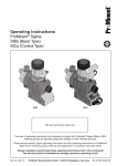
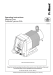
Operating Instructions
Metering Pump
ProMinent® CONCEPT b
60
70
30
90
10
lll
ll
50
40
80
0
20
10
l
Affix type identification plate here!
Please completly read through these operating instructions first! • Do not discard!
The warranty shall be invalidated by damage caused by operating errors!
Part No. 981766 ProMinent Dosiertechnik GmbH • 69123 Heidelberg • Germany
BA CO 006 06/99 GB
Key to Devices and Components
Detailed description of parts on Pages:
1
2
3
4
5
6
7
8
9
10
10 a
10 b
11
12
13
14
Frequency Selector Switch ................................................................. 12, 21
Stroke Length Adjustment Knob ...............................................12, 21, 23–25
Pulse/Operation Indicator (green/red/orange) .................................... 21, 22
Mains Power Connection..................................................................... 12, 13
Connection Socket for Level Switch .................................................... 11, 13
Connection Socket for External Activation ...................................... 11, 13, 21
Transparent Cover
Housing .............................................................................................. 23, 24
Head Valve ........................................................................................... 11, 12
for PP and NP Versions only
Bleeder Valve ............................................................................................ 12
Precision Bleeder Screw
Palm Grip
Bypass Hose Socket ................................................................................. 11
Liquid End ........................................................................................... 23, 24
End Disc .............................................................................................. 23, 24
Intake Valve ................................................................................................ 11
Imprint
Operating Instructions CONCEPT b
© ProMinent Dosiertechnik GmbH, 1996
ProMinent Dosiertechnik GmbH
Im Schuhmachergewann 5-11
D-69123 Heidelberg
P.O. Box 101760
D-69007 Heidelberg
[email protected]
www.prominent.de
Subject to modifications
Type setting/DTP:
Bartha Docuteam, D-64625 Bensheim
Issue 06/99
Printed in the F.R. Germany
Page 2 of 28
Version 1.0
Device Identification/Identity Code
Device Identification/Identity Code
The type identification plate affixed on the cover page is identical to that
of the supplied pump thus establishing distinct allocation between the
operating instructions and the pump. Please enter the identity code as
specified under "Type" on the type identification plate in the grey box
below.
IDENTITY CODE
CONb --- --- --- --- --- --- ---
Series:
CONCEPT
Version b
Pump type:
1st + 2nd figure
= Backpressure (bar)
3rd + 4th figure = Capacity (l/h)
120 strokes/min 180 strokes/min
1602
1601
1203
1201
1003
1002
0806
0803
0313
0308
0223
0215
Liquid end material:
NP6 = Acrylic/Viton®
PP1 = Polypropylene/EPDM
NS3 = Acrylic/Viton®
self-bleeding
= Special version
……………………
Valve spring:
0 = No spring
1 = With 2 valve springs
1.4571 - 0.1 bar
---
---
---
Connection:
0 = Standard in accordance
with technical data
= Special version
……………………
Transparent
cover:
0 = With PM-Logo
= Special version
……………………
Electrical connection:
A = 230 V, 2 m
Euro plug
B = 230 V, 2 m
Switzerland plug
C = 230 V, 2 m
Australian plug
D = 115 V, 2 m
USA plug
E = 200 V, 2 m
open cable end
F = 100 V, 2 m
Japan plug
= Special version
--- ---
--- ---
Control type:
0 = 3 selectable fixed
frequencies
1 = 2 fixed frequencies
and external
= Special version
……………………
Relay:
0 = Without relay
1 = Fault indicating relay, drop-out
2 = Clock generator relay, pick-up
3 = Fault indicating relay, pick-up
Accessories:
0 = No accessories
1 = With 1/2" metering valve
and foot valve
2 = With metering valve,
O-ring and foot valve
……………………
Viton® is a registered trademark of DuPont Dow Elastomers.
Version 1.0
Page 3 of 28
Contents
Page
Device Identification/Identity Code .................................................. 3
1
Foreword .................................................................................. 5
2
Functions .................................................................................. 5
2.1
3
Brief Description of Functions ......................................... 5
Technical Data ......................................................................... 5
3.1
General Data .................................................................. 5
3.2
Capacity Data ................................................................. 6
4
Installation Dimensions ............................................................ 7
5
Tests ........................................................................................ 8
6
Safety Notes............................................................................. 9
7
Installation .............................................................................. 10
8
9
7.1
Pump Installation .......................................................... 10
7.2
Hose Connections ........................................................ 11
7.3
Installation of Bypass Bleeder Line .............................. 11
7.4
Electrical Connections .................................................. 12
7.4.1
Connection of Control Cable and Level Switch . 12
7.4.2
Mains Power Connection ................................ 12
7.5
Start-Up ........................................................................ 12
7.6
Wiring Diagram ............................................................. 13
7.7
Determining Capacity by Means of Diagrams .............. 14
7.7.1
General ........................................................... 14
7.7.2
Diagram 1601, 1602 ....................................... 15
7.7.3
Diagram 1201, 1203 ....................................... 16
7.7.4
Diagram 0803, 0806 ....................................... 17
7.7.5
Diagram 1002, 1003 ....................................... 18
7.7.6
Diagram 0308, 0313 ....................................... 19
7.7.7
Diagram 0215, 0223 ....................................... 20
Operation and Setting ............................................................ 21
8.1
Stroke Length Setting ................................................... 21
8.2
Pump Frequencies ........................................................ 21
8.3
What is the Result of Incorrect Operation?................... 21
Maintenance ........................................................................... 21
10 Troubleshooting ..................................................................... 22
11 Repairs ................................................................................... 25
12 Spare Parts ............................................................................ 26
Page 4 of 28
Version 1.0
Foreword/Functions/Technical Data
1
Foreword
The ProMinent® CONCEPT is a microprocessor-controlled short-stroke
solenoid-operated diaphragm-type metering pump for metering liquid,
non-combustible media.
2
Functions
2.1
Brief Description of Functions
Metering is based on a pulsating action. For each pulse coming from the
electronic control, the solenoid energizes and completes a stroke of
max. 1.25 mm. The diaphragm, stabilized by a steel core, displaces the
medium in the liquid end, the balls on the intake side are pressed against
their seat while the balls on the delivery side open, thus releasing the
medium for metering. The solenoid is deactivated on completion of the
stroke and returned to its initial position by a spring. In so doing, the valve
on the delivery end closes while the valve on the intake side opens so as
to draw medium into the liquid end. The safety diaphragm protects the
leadthrough in the housing from dust and moisture.
The solenoid-operated, diaphragm-type metering pump covers a capacity
range from approx. 0.9 l/h to 23 l/h (litre specifications at max. stroke
length and max. stroke rate) at a max. backpressure of 1.5 bar to 16 bar.
The delivery capacity can be adjusted on the basis of the stroke length by
means of a rotary knob and the stroke rate by means of a switch. The
various operating statuses are indicated by an LED for operation and
empty/fault signal.
The pump features a connection facility for a single-stage level switch. In
addition to the internal mode of operation, external activation is also possible via floating contacts.
Metering deviations
Metering reproducibility
Permissible ambient temperature
Electrical connection
3
Technical Data
3.1
General Data
All material versions –5 % to +15 %
When used in accordance with operating instructions ±2 %
-10 °C to +45 °C
230 V, 50/60 Hz, +6 %, –10 %
115 V, 50/60 Hz, +6 %, –10 %
Mean power intake
Refer to type identification plate
Max. current consumption
Refer to type identification plate
Type of enclosure
Insulation class
Version 1.0
IP 65
F
Page 5 of 28
Technical Data
External contact activation:
Necessary contact duration
Contact load
20 ms
5 V; 0.5 mA
Contact load
Fault indicating relay (option)
250 V; 2 A
Contact load
Clock generator relay (option)
42 V; 0.1 A
3.2
Capacity Data
Pump type
Pump type CONb
with 120 strokes/minute
1601
1201
0803
1002
0308
0215
Max. capacity (l/h)
Capacity (ml/stroke)
At max. backpressure (bar)
1.0
0.14
16
1.7
0.24
12
3.4
0.48
8
2.3
0.32
10
8.4
1.17
3
14.8
2.05
1.5
Max. capacity (l/h)
Capacity (ml/stroke)
At mean backpressure (bar)
1.2
0.17
8.0
1.9
0.27
6.0
3.8
0.53
4.0
2.6
0.36
5.0
9.1
1.23
1.5
15.80
2.20
1.0
Stroke rate (strokes/min)
120
120
120
120
120
120
Connection size 0 ø x i ø (mm)
6x4
6x4
6x4
8x5
8x5
12x9
Suction head (m water column)
6.0
6.0
3.0
6.0
6.0
1.5
Intake head (m water column)
1.8
2.5
2.8
2.0
1.8
1.5
Permissible admission pressure
intake side (bar)
8.0
5.5
3.0
3.0
1.5
0.8
Pump type
CONb with 180 strokes/min
1602
1203
0806
1003
0313
0223
Max. capacity (l/h)
Capacity (ml/stroke)
At max. backpressure (bar)
1.5
0.14
16
2.5
0.24
12
5.3
0.48
8
3.4
0.31
10
13.0
1.20
3
23.0
2.13
1.5
Max. capacity (l/h)
Capacity (ml/stroke)
At mean backpressure (bar)
1.8
0.17
8.0
2.9
0.27
6.0
5.6
0.53
4.0
3.7
0.34
5,0
15.5
1.43
1.5
25.5
2.36
1.0
Stroke rate (strokes/min)
180
180
180
180
180
180
Connection size 0 ø x i ø (mm)
6x4
6x4
6x4
8x5
8x5
12x9
Suction head (m water column)
6.0
6.0
3.0
6.0
6.0
1.5
Intake head (m water column)
1.8
2.5
2.8
2.0
1.8
1.5
Permissible admission pressure
intake side (bar)
8.0
5.5
3.0
3.0
1.5
0.8
Page 6 of 28
Version 1.0
Installation Dimensions
4
CONb
Installation Dimensions
A
B
C
D
E
F
G
1601, 1201
1602, 1203
PP
NP
225
223
180
173
11
13
70
70
6x4
6x4
88
88
38
38
0803, 0806
PP
NP
225
223
180
173
11
13
70
70
6x4
6x4
88
88
38
38
1002, 1003
PP
NP
218
216
180
181
11
5
70
85
8x5
8x5
83
83
50
50
0308, 0313
PP
NP
218
216
180
181
11
5
70
85
8x5
8x5
82
82
50
50
0215, 0223
PP
NP
218
216
191
189
0
–3
90
100
12x9
12x9
83
83
66
66
Version 1.0
Page 7 of 28
Tests
EC Declaration of Conformity
We,
ProMinent Dosiertechnik GmbH
Im Schuhmachergewann 5 - 11
D - 69123 Heidelberg
hereby declare that, on the basis of its functional concept and design and in the version brought into
circulation by us, the product specified in the following complies with the relevant, fundamental safety and
health stipulations laid down by EC regulations.
Any modification to the product not approved by us will invalidate this declaration.
Product description:
Metering pump, Series CONCEPT
Product type:
CONb.... ,
Serial number:
see type identification plate overleaf and on device
Relevant EC
regulations:
EC-machine regulation (89/392/EEC) subsequently 93/44/EEC
EC-low voltage regulation (73/23/EEC)
EC-EMC-regulation 89/336/EEC subsequently 92/31/EEC
Harmonised standards used,
in particular:
EN 292-1 , EN 292-2 , EN 809
EN 60335-1 A6 , EN 60335-2-41
EN 50081-1/2 , EN 50082-1/2 , EN 55014
EN 60555-2 , EN 60555-3
National standards and technical
specifications used,
in particular:
DIN VDE 0700 T1
DIN VDE 0700 T41
DIN VDE 0700 T500
CSA Standard C 22.2 No.
0-M 91 (115 V-Version)
CSA Standard C 22.2 No. 108-M 89 (115 V-Version)
Date/manufacturer's signature:
28.03.1996 ........................................................................
The undersigned:
Mister Manfred Hüholt, factury manager
Page 8 of 28
Version 1.0
Safety Notes
6
Safety Notes
ProMinent® metering pumps must not be assembled with
parts which have not been tested and recommended by
ProMinent otherwise this can lead to injury to persons and
damage to property for which no liability will be accepted!
Pumps must be accessible at all times to facilitate operation
and maintenance. Access points must not be obstructed or
blocked!
When metering hazardous or unknown liquids, always
wear safety clothing (safety goggles, gloves) when working
on the liquid end!
Before carrying out any maintenance and repair work always
drain off and flush out the liquid end first if hazardous or
unknown metered media are used! Observe data sheets of
metered liquids!
The metering pump can contain water residue in the liquid
end as the result of testing at the factory! If handling media
which must not come in contact with water, all traces of water
must be removed from the liquid end before start-up! For this
purpose, turn the pump through 180° and drain off the liquid
end then flush with a suitable medium from
above via the intake connection.
Always depressurize the delivery line first before carrying
out any work on the pump! Always discharge and flush
liquid end! Observe safety data sheets for metered liquid!
WARNING:
When operating the metering pump against a closed shutoff element on the delivery side, the resulting pressure
buildup can reach a multiple of the maximum permissible
backpressure!
This can cause the delivery line to burst!
To avoid this, it is advisable to install a ProMinent
multifunction valve which limits the maximum pressure
which can be reached!
The stroke length should only be set with the pump in operation
– when the load on the metering stroke setting pin is relieved
temporarily – only use the clamping rings and hose sockets
intended for the relevant hose diameter as well as original
hoses with the specified hose size and wall thicknesses
otherwise the stability and durability of the connection will not
be guaranteed!
Avoid reducing hose sizes!
The next higher line cross-section or a pulsation damper should be
used for longer lines and high-viscosity media.
Version 1.0
Page 9 of 28
Safety Note/Installation
DANGER:
Only qualified electricians are permitted to carry out
electrical repairs (safety regulations of Employer's Liability
Insurance Association: VBG 4 and ZH 1/11)!
DANGER:
Disconnect power plug or power supply line before opening
the pump! Isolate relay option if applicable! Check to
ensure power is disconnected! Secure pump while carrying
out repairs to ensure it cannot be switched on
unintentionally!
WARNING:
Only specially trained and authorized personnel are
permitted to carry out repairs on metering pumps!
7
Installation
7.1
Pump Installation
Spring-loaded metering valve
Metering pump
Metering tank
Foot valve with sieve and ball check valve
CONb-003-GB
Page 10 of 28
•
Mount metering pump on a tank or support bracket with bolts and
U-washers (Ø 5 mm).
•
To ensure efficient operation, the valves of the liquid end must
always be positioned vertically.
•
Shorten intake lines such that the foot valve hangs approx. 10 – 30 mm
(approx. 50 mm for heavily soiled metering solutions) over the bottom
of the tank.
•
Install delivery line and metering valve, pressure retension valve for
free outlet.
Version 1.0
Installation
7.2
Hose Connections
•
Fit union nut and clamping ring over hose line.
•
Push the hose end, cut at right angles, onto socket as far as it will
go.
•
Slightly widen hose end if necessary.
•
Shorten hose end at right angles by approx. 10 mm for connecting
several times.
•
Press on hose and firmly tighten union nut.
Union
nut >
Hose
line
>
Socket >
< Clamping ring >
(Installation position)
O-ring >
CONb-004-GB
7.3
Liquid end with bleeder valve
Installation of Bypass Bleeder Line
The bleeder valve (10) with bypass (11) is provided on the liquid end
in the versions NP and PP up to Type 0417.
• Fit 4 mm inside Ø (max. 6 mm) hose on to bypass hose socket,
preferably use 6 x 4 mm soft PVC.
• If PE lines are used, secure with a cable tie to prevent slipping.
• Insert free end of hose line in metering tank.
• Connect delivery line directly to delivery connection and metering
valve.
Version 1.0
Page 11 of 28
Installation
7.4
Electrical Connections
7.4.1
Connection of Control Cable and Level Switch
•
If applicable, connect level switch to connection socket (5) on the
pump.
•
If provided, connect contact/control cable or universal control cable
to the pump connection socket (6).
2-core contact control cable
If the 2-core contact control cable is connected, the pump is
switched over to external mode by the pressures "1–4" in the clutch.
In addition, the frequency selector switch (1) must be set to position
"1" .
4-core universal control cable
If the 4-core universal control cable is used, the brown and black
cores for changeover to external mode should be connected by wire
jumpers. If necessary, the pump can be stopped potential-free in
internal mode with the aid of this circuit or the frequency changeover
(blue core).
7.4.2
•
Mains Power Connection
Connect mains power plug in the socket provided
ATTENTION:
Take particular care to ensure that the mains voltage agrees
with ratings on the type identification plate. A separate switching
contact, e.g. relay or contactor should be provided for parallel
connection with inductive loads.
7.5
Page 12 of 28
Start-Up
•
In order to prime the metering pump, if necessary, remove external
cable, set stroke length knob (2) to 100 % and stroke rate setting
knob (1) to III.
•
Open bleeder valve by approx. 1 turn.
•
Allow pump to run until a little of the chemical is visible in the delivery
line or emerges at the bleeder valve.
•
On metering pumps without a bleeder valve, the delivery line must
be released at the liquid end or a multifunction valve should be
used.
•
After priming, close bleeder valve (10) or resecure delivery line at
metering valve.
Version 1.0
Installation
7.6
Wiring Diagram
View of connector block on pump
2
1
1
3
2
4
Relay cable
(option)
NC
C
N0
External input
115 Volts
red = NC
white = N0
black = C
Socket assignments:
Power connection cable
230 Volts
green = NC
white = N0
brown = C
External activation
:
Level switch
:
1 = External switchover (+5 V)
1 = End cutout (+5 V)
2 = External contact (+5 V)
2 = GND
3 = Floating frequency switchover to F3
4 = GND
View of cable sockets on control cable (2-pin or 4-pin) or on level switch connection cable
2
2
3
1
3
black
brown
brown
white
white
4
4
blue
1
External/contact cable:
Universal control cable:
Close contact metering stroke
External switchover: 1 brown + 4 black/GND
brown + black connected = Pump in external mode, brown + black open = Pump meters in internal mode
External/contact: 2 white + 4 black/GND
Close contact - metering stroke (1 and 4 connected by jumper)
Frequency changeover: 3 blue + 4 black/GND
Close contact - pump operates with F3
Version 1.0
CONb-005-GB
Page 13 of 28
Installation
7.7
Determining Delivery Capacity by Means of Diagrams
7.7.1
General
1. Determine required delivery capacity.
2. Determine correction factor in accordance with the diagram "Capacity
as a Function of Backpressure".
3. Divide required delivery capacity by correction factor.
4. Find calculated value on the vertical scale in the diagram "Capacity
at Mean Backpressure" and draw a horizontal line from this point
over the entire diagram.
5. Draw a vertical line from the point of intersection with the frequency
characteristic curve down to the stroke length scale. Read off the
stroke length.
6. Set determined stroke length on the pump.
7. Set pump frequency rate on the pump as indicated at the point of
intersection on the frequency curve.
8. If the horizontal line intersects two frequency characteristic curves
starting from the capacity scale in the diagram "Capacity at Mean
Backpressure", if there are no other compelling reasons, the lower
frequency should be selected for the sake of metering accuracy.
9. The result obtained in this way is a reference value. To obtain
accurate metering, the delivery capacity must be monitored and
corrected if necessary.
10. Refer to Technical Data for metering accuracy.
11. The capacity data are referred to water, the correction factor was
determined at a stroke length of 70 %.
Example: Metering pump Type 1201
Page 14 of 28
•
Required metering capacity 0.7 l/h at 8 bar
•
Correction factor at 8 bar in accordance with diagram = 0.85
Delivery capacity for diagram = 0.7 l/h/0.85 = 0.82
•
The horizontal line drawn at 0.82 l/h intersects two frequency
characteristic curves. The frequency curve which results in the
highest stroke length should be selected. Here in this example this
is the frequency characteristic curve with 60 strokes/min. Set this
frequency on the pump.
•
The value obtained for the stroke length is 92 %.
•
Diagrams for examples (refer to Pages 15 to 20).
Version 1.0
Version 1.0
Delivery capacity l/h
Korrekturfaktor
Correction factor
Facteur de correction
0,5
1
1,5
0
0,2
0,4
0,6
0,8
1,0
1,2
1,4
1,6
1,8
0
0
20
30
50
60
Stroke length in %
40
70
1.5
4
6
8
10
Förderleistung in Abhängigkeit vom Gegendruck
Rating in relation to backpressure
Débit fonction de la contre-pression
10
Capacity at mean backpressure
stroke rate 1/min
12
80
14
90 100
CONb-1601-D
16 bar
30 strokes 1/min
60 strokes 1/min
120 strokes 1/min
0,5
1
1,5
0
0,2
0,4
0,6
0,8
1,0
1,2
1,4
1,6
1,8
2,0
0
0
20
30
50
60
Stroke length in %
40
70
1.5
4
6
8
10
12
Förderleistung in Abhängigkeit vom Gegendruck
Rating in relation to backpressure
Débit fonction de la contre-pression
10
Capacity at mean backpressure
stroke rate 1/min
Diagram CONb 1602
80
14
90
16 bar
100
CONb-1602-D
45 strokes 1/min
90 strokes 1/min
180 strokes 1/min
7.7.2
Delivery capacity l/h
Korrekturfaktor
Correction factor
Facteur de correction
Diagram CONb 1601
Installation
Diagram 1601, 1602
Page 15 of 28
Page 16 of 28
Delivery capacity l/h
Korrekturfaktor
Correction factor
Facteur de correction
0,5
1
1,5
0
0,2
0,4
0,6
0,8
1,0
1,2
1,4
1,6
1,8
2,0
0
0
20
40
50
Stroke length in %
30
60
70
1.5 2
3
4
5
6
7
Förderleistung in Abhängigkeit vom Gegendruck
Rating in relation to backpressure
Débit fonction de la contre-pression
10
Capacity at mean backpressure
stroke rate 1/min
8
80
9
90
10
100
12 bar
CONb-1201-D
11
30 strokes 1/min
60 strokes 1/min
120 strokes 1/min
0,5
1
1,5
0
0,5
1
1,5
2
2,5
3
0
0
20
30
40
50
60
Stroke length in %
70
3
4
5
6
7
8
9
Förderleistung in Abhängigkeit vom Gegendruck
Rating in relation to backpressure
Débit fonction de la contre-pression
1.5 2
10
Capacity at mean backpressure
stroke rate 1/min
Diagram CONb 1203
80
10
11
90
CONb-1203-D
12 bar
100
45 strokes 1/min
90 strokes 1/min
180 strokes 1/min
7.7.3
Delivery capacity l/h
Korrekturfaktor
Correction factor
Facteur de correction
Diagramm CONb 1201
Installation
Diagram 1201, 1203
Version 1.0
Version 1.0
0
0,5
1
1,5
2
2,5
3
3,5
4
0
Korrekturfaktor
Correction factor
Facteur de correction
0,5
1
1,5
10
0
40
50
Stroke length in %
30
60
70
80
1
1,5 2
3
4
5
Förderleistung in Abhängigkeit vom Gegendruck
Rating in relation to backpressure
Débit fonction de la contre-pression
20
Capacity at mean backpressure
stroke rate 1/min
6
90
7
100
CONb-0803-D
8 bar
30 strokes 1/min
60 strokes 1/min
120 strokes 1/min
0
1
2
3
4
5
6
0
0,5
1
1,5
0
10
20
50
60
Stroke length in %
40
70
80
90
1 1.5
2
3
4
5
6
Förderleistung in Abhängigkeit vom Gegendruck
Rating in relation to backpressure
Débit fonction de la contre-pression
30
Capacity at mean backpressure
stroke rate 1/min
Diagram CONb 0806
7
100
CONb-0806-D
8 bar
45 strokes 1/min
90 strokes 1/min
180 strokes 1/min
7.7.4
Korrekturfaktor
Correction factor
Facteur de correction
Diagram CONb 0803
Installation
Diagram 0803, 0806
Page 17 of 28
Delivery capacity l/h
Delivery capacity l/h
0
0,5
1
1,5
2
2,5
3
0
0,5
0
20
40
50
60
1.5 2
70
80
90
100
3
4
5
6
7
8
9
10
Förderleistung in Abhängigkeit vom Gegendruck
Rating in relation to backpressure
Débit fonction de la contre-pression
Stroke length in %
30
CONb-1002-D
bar
30 strokes 1/min
60 strokes 1/min
120 strokes 1/min
0
0,5
1
1,5
2
2,5
3
3,5
4
0
0,5
1
1,5
0
10
30
1.5 2
20
50
60
70
80
90
3
4
5
6
7
8
9
10 bar
45 strokes 1/min
CONb-1003-D
90 strokes 1/min
180 strokes 1/min
100
Förderleistung in Abhängigkeit vom Gegendruck
Rating in relation to backpressure
Débit fonction de la contre-pression
Stroke length in %
40
Capacity at mean backpressure
stroke rate 1/min
Diagram 1002, 1003
1
1,5
10
Capacity at mean backpressure
stroke rate 1/min
Diagram CONb 1003
7.7.5
Korrekturfaktor
Correction factor
Facteur de correction
Page 18 of 28
Delivery capacity l/h
Korrekturfaktor
Correction factor
Facteur de correction
Diagram CONb 1002
Installation
Version 1.0
Delivery capacity l/h
Version 1.0
CONb-0308-D
30 strokes 1/min
60 strokes 1/min
120 strokes 1/min
Förderleistung in Abhängigkeit vom Gegendruck
Rating in relation to backpressure
Débit fonction de la contre-pression
Stroke length in %
Capacity at mean backpressure
stroke rate 1/min
Diagram CONb 0313
45 strokes 1/min
90 strokes 1/min
180 strokes 1/min
7.7.6
Förderleistung in Abhängigkeit vom Gegendruck
Rating in relation to backpressure
Débit fonction de la contre-pression
Stroke length in %
Capacity at mean backpressure
stroke rate 1/min
Diagram CONb 0308
Installation
Diagram 0308, 0313
Page 19 of 28
Delivery capacity l/h
Delivery capacity l/h
Page 20 of 28
30 strokes 1/min
60 strokes 1/min
120 strokes 1/min
Förderleistung in Abhängigkeit vom Gegendruck
Rating in relation to backpressure
Débit fonction de la contre-pression
Stroke length in %
Capacity at mean backpressure
stroke rate 1/min
Diagram CONb 0223
45 strokes 1/min
90 strokes 1/min
180 strokes 1/min
7.7.7
Förderleistung in Abhängigkeit vom Gegendruck
Rating in relation to backpressure
Débit fonction de la contre-pression
Stroke length in %
Capacity at mean backpressure
stroke rate 1/min
Diagram CONb 0215
Installation
Diagram 0215, 0223
Version 1.0
Delivery capacity l/h
Delivery capacity l/h
Operation/Maintenance
8
Operation and Setting
8.1
Stroke Length Setting
This setting is determined by means of a diagram (refer to Page 15 to 20)
and set with the stroke length setting knob (2).
8.2
Pump Frequencies (Rates)
The stroke rate is set by means of the frequency selector switch (1):
Setting III corresponds to 100 %, setting II 50 % and setting I, depending
on type of control, 25 % or 0 % stroke rate
8.3
Control type
III
II
I
External
0
120/180
60/90
30/45
–
1
120/180
60/90
0
+
What is the Result of Incorrect Operation?
The control cable must be disconnected when priming externally activated
pumps. Overmetering may occur if this cable is not reconnected after
priming. This could lead to serious damage in certain applications, e.g.
disinfection of drinking water with chlorine bleaching agent.
The LED (3) lights orange if an illogical setting is made on the pump, e.g.
external connector (6) is plugged in and switch (1) is set in position II
or III.
9
Maintenance
Maintenance of the CONCEPT metering pump is restricted to checking
• the liquid end screws (firm fit)
• the delivery lines (firm fit)
• the head and intake valves (firm fit)
• the leakage hole at the end disc (moisture can indicate diaphragm
failure)
Version 1.0
Page 21 of 28
Troubleshooting
10
Troubleshooting
Breakdown assistance
In order to be able to repair a small breakdown at any time, we recommend
to always keep a spare parts kit in stock - consisting of diaphragm, valves,
balls and seals. See Page 26 for order information.
No pump intake despite full stroke movement and venting
Possible cause:
Crystalline deposits caused by valves drying out
Remedy:
• Remove intake hose out of metering tank and thoroughly flush out
liquid end
• If this provides no improvement, remove and clean valves
• The valve seat in the intake and head valve can be pressed out with
a 3 mm ø drift.
Warning lamp (3) lights red
Possible cause:
Chemical deficiency
Remedy:
• The fault signal is acknowledged automatically by filling the supply
tank
Warning lamp (3) lights orange
Possible cause:
•
External cable connected and
frequency selector switch not set to position I.
Remedy:
• If external mode is required, set frequency selector switch to
position I.
• If internal mode is required, disconnect external control cable.
Liquid emerges at head end
Possible cause:
Delivery unit leaking at metering diaphragm
Remedy:
• Retighten screws in liquid end crosswise.
• If liquid still leaks out this indicates the diaphragm has failed and
must be replaced.
Page 22 of 28
Version 1.0
Troubleshooting
Replacing metering diaphragm
• With pump in operation, set stroke length to "0" with rotary knob (2)
• Release screws (15)
13
13a
8
12
15
m
m
.5
x
ro
p
ap
CONb-006-GB
• Pull liquid end (12) together with screws out of end disc (13) and pump
housing (8) (approx. 5 mm) until the screws no longer offer any
resistance when turning the liquid end.
• Hold housing (8) in the left hand and release diaphragm (13a) with
the right hand by lightly jolting liquid end (12) together with end disc
(13) in counterclockwise direction and release screws (15) from
drive spindle (13b).
13
12
8
13a
15
m
x
ro
13 b
p
ap
m
.5
CONb-007-D
Version 1.0
Page 23 of 28
Troubleshooting
• Now pull liquid end together with screws out of diaphragm and
unscrew the entire assembly from the drive spindle.
• Remove diaphragm (13a) from end disc (13).
13
8
13a
12
15
13b
CONb-008-D
• Screw on new diaphragm (13a) as far as it will go on drive spindle
(13b) and check thread movement.
• Once again remove diaphragm from drive spindle.
• Fit end disc on housing.
• Insert diaphragm in end disc and screw on by 2 thread turn
ATTENTION:
Turn diaphragm such that the 4 holes in the diaphragm and end
disc are precisely aligned! The outlet in the end disc must face
downward!
• Fit liquid end (intake connection must face downward!) with screws on
to diaphragm and end disc (once again leave approx. 5 mm space
between liquid end and end disc) such that the parts can still be turned.
• Now slowly turn parts in clockwise direction until diaphragm is firmly
fitted (resistance of return spring can be felt)
ATTENTION:
Do not overturn diaphragm, particularly in Type 1601!
Page 24 of 28
Version 1.0
Troubleshooting/Repair
• Set stroke length to 100 % with rotary knob (2) and, with metering
pump running, slowly turn the complete delivery unit in clockwise
direction until the intake connection faces vertically downward.
• Stop pump.
• Tighten 4 screws (15) crosswise.
ATTENTION:
Observe screw tightening torques!
Tightening torque for screws
2.5 to 3 Nm
M4:
M5:
4.5 to 5 Nm
NOTE:
Check the tightening torque of the liquid end screws after 24 hours
of operation!
Additionally check the tightening torques on PP pumps every
3 months!
• Set required stroke length with pump in operation.
11
Repair
Return the metering pump for repair only in a clean condition
with the liquid end flushed clean.
Pumps which are used for metering radioactive media must
not be shipped!
Version 1.0
Page 25 of 28
Spare Parts
12
Spare Parts
In order to repair small breakdowns at any time we recommend to always
keep a spare parts kit in stock. This kit contains the following wearing or
spare parts:
1 Intake valve, complete
1 Head valve, complete
1 Set of seals
1 Metering diaphragm
1 Set of connection parts
Additionally for NS 3 (self-bleeding) version:
1 Bleeder valve, complete
1 Connection for delivery side or bypass
Spare parts kit for
Pump type:
Order number
1601/1602 PP1 ..................................... 74.03.61.1
1201/1203 PP1 ..................................... 74.03.80.1
0803/0806 PP1 ..................................... 74.03.84.3
1002/1003 PP1 ..................................... 74.03.88.4
0308/0313 PP1 ..................................... 74.04.97.3
0215/0223 PP1 ..................................... 74.04.99.9
1601/1602 NP6 ..................................... 74.05.51.7
1201/1203 NP6 ..................................... 74.05.52.5
0803/0806 NP6 ..................................... 74.05.53.3
1002/1003 NP6 ..................................... 74.05.54.1
0308/0313 NP6 ..................................... 74.05.55.8
0215/0223 NP6 ..................................... 74.05.56.6
1601/1602 NS3 ..................................... 79.20.33.3
1201/1203 NS3 ..................................... 79.20.34.1
0803/0806 NS3 ..................................... 79.20.35.8
1002/1003 NS3 ..................................... 79.20.36.6
Page 26 of 28
Version 1.0
Notes
Version 1.0
Page 27 of 28
Page 28 of 28
Version 1.0