1
Operating Instructions
BKS24-9A
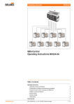
SBS-Control
Operating Instructions BKS24-9A
Table of contents
Operating Instructions
1 Operating controls and indicators
2
2 Preparations for faultless commissioning and operating
3
3 Programming the number of dampers per BKS24-9A
4
4 Adding / removing of dampers
5
5 System testing
6
6 Function testing
7
7 Fault alarms
8
Technical data
www.belimo.com
M3-A12-BKS24-9A • en • v2.1 • 11.2009 • Subject to changes
9
/ 12
BKS24-9A
SBS-Control
1 Operating controls and indicators
a
b
c
d
e
f
g
h
i
/ 12
a
Retaining-Clip
Lift clip with Screwdriver for mounting-/removing
b
Label
For zone identification
c
Label 1 … 9
For damper identification
d
LEDs (red) FAULT dampers
1…9
Off
Flashing
On
e
Pushbutton PRG.
–Programming the number of dampers
–Check the number of dampers
f
LED (green) NORMAL Position
Flashing
On
=Dampers run to NORMAL Position (OPEN)
=Dampers have reached NORMAL Position
g
LED (yellow) SAFE Position
Flashing
On
=Dampers run to SAFE Position (CLOSE)
=Dampers have reached SAFE Position
h
Pushbutton TEST
–System Test
–Functional Test
i
Electrical connection
9-Pin Terminal Connectors
(This pushbutton is recessed, use a proper
tool to operate).
=No alarm
=Alarm present
=Alarm stored
M3-A12-BKS24-9A • en • v2.1 • 11.2009 • Subject to changes
(Dampers/Actuators/Control Unit)
(for checking the system manually)
www.belimo.com
BKS24-9A
SBS-Control
2 Preparations for faultless commissioning and operating
• Fire dampers are installed and mechanically tested
2.1
• OPEN and CLOSED end positions attainable
2.2
• Fire damper actuators (AC 24 V) connected (both cables)
to the BKN230-24 or BKN230-24-C-MP units
2.3
• Terminals 1 to 7 of the BKN230-24 or BKN230-24-C-MP
unit correctly wired according to the wiring diagram and
technical documentation
..
..
.
..
..
.
• Ensure correct polarity when connecting the 2-wire
conductors (terminals 6 and 7)
2.4
• All BKN230-24 and BKN230-24-C-MP units connected
to the AC 230 V power supply (by mains connector or
terminal box)
AC 230 V
• Number and sequence of connected dampers labelled
and programmed (e.g.1 … 5) on the front of the
BKS24-9A unit
2.5
Zone 1a
BSK 34
BSK 37
BSK 35
BSK 38
• Programming see Para. 3
BSK 36
2.6
AC 24 V
T
T
11
~
12
~
BKS24-9A
• OPEN Command is present at the BKS24-9A unit
causing the dampers to be moved to the operating
position
Control ON
(OPEN)
13
14 Programming input
• All other inputs correctly wired according to the wiring
diagram and thetechnical documentation
2.7
1
9 10
18
www.belimo.com
M3-A12-BKS24-9A • en • v2.1 • 11.2009 • Subject to changes
/ 12
..
..
.
BKS24-9A
SBS-Control
3 Programming the number of dampers per BKS24-9A
• Factory programmig:
The BKS24-9A unit is factory programmed for 9 dampers
Targets
1
9
• The programming must be modified accordingly when
connecting 1 to 8 dampers
1
8
3.1 … 3.5 Procedure
3.1
Note preparatory work in Para. 2
!
• Press and hold PRG. key (until 3.5 included)
3.2
3.3
Zone 1a
BSK 34
BSK 37
BSK 35
BSK 38
• The fault LEDs for the number of dampers programmed
light up for 4 seconds (e.g. 1 to 9)
BSK 36
3.4
Zone 1a
BSK 34
BSK 37
BSK 35
BSK 38
BSK 36
3.5
• The fault LEDs for the number of dampers programmed
and acknowledged by the BKS24-9A unit start flashing
(e.g. 1 to 5)
• The number of dampers acknowleged must correspond to
the number of dampers labelled
• Press the TEST key at the same time as the PRG. key
• The numer of dampers acknowledged is now programmed
in the BKS24-9A unit
Note
A System test is initiated automatically
(see Para. 5)
/ 12
M3-A12-BKS24-9A • en • v2.1 • 11.2009 • Subject to changes
www.belimo.com
BKS24-9A
SBS-Control
4 Adding / removing of dampers
Example
A fire damper is to be added to an existing system, resp. or is beeing removed.
The dampers 1 to 5 are in operation and damper 6 is the new one, or but, damper 5 is being
removed.
The comment in (bold italics) refers to the removal of a damper.
4.1 … 4.5 Procedure
4.1
!
• Note preparatory work in Para. 2
• An automatic system test is performed when the power supply (AC 24 V) is energised (see
Para. 5)
• Start flashing:
– The status LED for OPEN and the fault LED of the new damper 6, or
– The status LED for OPEN and the fault LED of the removed damper 5
• Label adapting on the front of the BKS24-9A unit
Dampers 1 … 4 or
Dampers 1 … 6
4.2
• Press and hold the PRG. key
4.3
Zone 1a
BSK 34
BSK 37
BSK 35
BSK 38
BSK 36
BSK 39
4.4
Zone 1a
BSK 34
BSK 37
BSK 35
BSK 38
BSK 36
BSK 39
• The fault LED for the five dampers programmed (see
example) light up for 4 Seconds
• The fault LEDs for the number of dampers programmed
and acknowledged by the BKS24-9A unit start flashing
– after adding a damper actuator the fault LED 1 to 6 start
flashing
– after removing a damper actuator the fault LED 1 to 4
start flashing
• The number of dampers acknowledged must correspond
to the number of dampers labelled
4.5
• Press the TEST key at the same time as the PRG. key
• The number of dampers acknowledged is now
programmed in the BKS24-9A unit
Note
A System test is initiated automatically
(see Para. 5)
www.belimo.com
M3-A12-BKS24-9A • en • v2.1 • 11.2009 • Subject to changes
/ 12
BKS24-9A
SBS-Control
5 System testing
!
• The system test deals with the connected dampers, the actuators, the installation and the
control unit
• Note preparatory work in Para. 2
• The dampers are moved to the OPEN and CLOSED position during the test
5.1 Initiation criteria
a) Automatic
–After programming of connecting
–After powering up (AC 24 V)
b) After a fault alarm
–By pressing the TEST key
5.2 … 5.7 Procedure
5.2
• All 11 LEDs light up for 4 Seconds (lamptest)
5.3
• The OPEN/CLOSED status LEDs flash alternately for
the duration of the system test
5.4
• The dampers are moved in the CLOSED direction and
must attain the safe postion
5.5
• The dampers are moved in the OPEN direction and must
attain the operating position (as described in Para. 2.6)
5.6
• The status LED for OPEN starts flashing when the
damper departs from the safe position
• The status LED for OPEN gives a steady light when the
damper reaches the operating position
• The system is now ready to use
5.7
o.k.
/ 12
M3-A12-BKS24-9A • en • v2.1 • 11.2009 • Subject to changes
www.belimo.com
BKS24-9A
SBS-Control
6 Function testing
!
• The purpose of the function test is for checking the system manually
• Note preparatory work in Para. 2
• The connected fire dampers are moved to the CLOSED and OPEN positions
6.1 Initiation criteria
• Press and hold the TEST key
6.2 … 6.6 Procedure
6.2
• The status LED for OPEN lights up
• All fire dampers are in the operating position (OPEN)
• The fault LEDs 1 to 9 are off
• Press and hold the TEST key
6.3
• The staus LED for CLOSED will start flashing
• When the status LED for CLOSED gives a steady light it
means that the dampers have reached the safe position
6.4
• Release the TEST key
• The dampers move to the operating position
6.5
• When the status LED for OPEN gives a steady light
it means that the function test has been completed
successfully
• The system is ready for use
6.6
o.k.
www.belimo.com
M3-A12-BKS24-9A • en • v2.1 • 11.2009 • Subject to changes
/ 12
BKS24-9A
SBS-Control
7 Fault alarms
Fault in the system
7.1 Existing fault
• Fault LED flashing (e.g. damper 4)
!
• Status LED for OPEN or CLOSED flashing (depending
on control signal)
►Existing fault
Note
Possible causes see Para. 7.3
►Contact K1 open
Temporary fault in the system
7.2 Stored fault
• Fault LED bright (e.g. damper 4)
!
►Stored fault
►Contact K1 closed
• A stored fault can be acknowledged in two ways:
1.Manually with the TEST key (see Para. 4)
2.Automatically when the dampers have run properly to
two successive end positions OPEN / CLOSED
7.3 Initiation criteria
• When a fire damper does not reach the operating position or safe position within the specified
running time
► Para. 2.1
• Open-circuit or wrong polarity on 2-wire conductor
►Para. 2.4 to 2.7
• Open-circuit or fault in the Tripping Device BAE72-S
►Para. 2.4
..
..
.
• No power supply or fault in the BKN230-24 or BKN230-24-C-MP unit
►Para. 2.3
..
..
..
..
..
• Open-circuit or fault at the plug connections from damper actuator to the BKN230-24 or
BKN230-24-C-MP unit
►Para. 2.2
• After adding a damper actuator to or removing one from an existing system
►Para. 4
7.4 Unit fault
!
/ 12
Fault in the BKS24-9A unit
• All 11 LEDs on the BKS24-9A unit flash in unison
►It means that the BKS24-9A unit is defective and must be replaced
M3-A12-BKS24-9A • en • v2.1 • 11.2009 • Subject to changes
www.belimo.com
Technical data
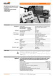
BKS24-9A
Communication and control unit
for control and monitoring of up to nine
motorized fire dampers in combination
with the communication and power supply
units BKN230-24 or BKN230-24-C-MP
•Signals the operating positions and any
faults from the fire dampers to which it is
connected.
•Reduced wiring costs due to 2-wire
communication
•Propagation of group alarm and damper
position to an overhead system via
auxiliary contacts
•Panel mounting (DIN rail)
..
..
.
Technical data
Electrical data
Safety
Dimensions / Weight
Nominal voltage
Power supply range
Power consumption In operation
For wire sizing
Connection
Lenghts of conductors 2-wire conductors a/b
control input 13
Auxiliary contacts
AC 24 V, 50/60 Hz
AC 21,6 ... 28,8 V
3.5 W
5.5 VA (I max. 6.4 A at 2.5 ms)
Terminals for 2 x 1.5 mm2
max. 600 m (wire 0.75 mm2)
max. 600 m (wire 0.75 mm2)
AC 24 V at 0.5 A
Protection class
Degree of protection
EMC
Mode of operation
Rated impulse voltage
Control pollution degree
Ambient temperature
Non-operating temperature
Maintenance
III safety extra-low voltage / UL Class 2 Supply
IP20
CE according to 2004/108/EG
Type 1 (EN 60730-1)
0.5 kV (EN 60730-1)
2 (EN 60730-1)
0 ... +50°C
–30 ... +50°C
Maintenance-free
Dimensions
Weight
See «Dimensions» on page 2
Approx. 160 g
Safety notes
!
• The device is not allowed to be used outside the specified field of application, especially in
aircraft or in any other airborne means of transport.
• It may only be installed by suitably trained personnel. Any legal regulations or regulations
issued by authorities must be observed during assembly.
• The device may only be opened at the manufacturer’s site. It does not contain any parts that
can be replaced or repaired by the user.
• The device contains electrical and electronic components and is not allowed to be disposed
of as household refuse. All locally valid regulations and requirements must be observed.
Product features
Mode of operation
The BKS24-9A unit receives position signals from the BKN230-24 or the BKN230-24-C-MP
units and transmits control commands to them over the 2-wire conductors.
Correct operation of the dampers is indicated by the 2 LEDs:
Control ON = NORMAL Position
Control OFF = SAFE Position
Fault
If the damper does not reach the required position within the preset time, the appropriate
on-board FAULT LED flashes and, at the same time, the FAULT contact K1 is activated.
This contact is overridden as soon the defective damper reaches the requried position. The
on-board FAULT LED remains on, until the fault is reset.
Auxiliary contact K2
www.belimo.com
An auxiliary contact is provided for signaling the positions of dampers to a higher-level system.
The function of the auxiliary contact can be programmed via terminal 14 according to the
instructions beside.
M3-A12-BKS24-9A • en • v2.1 • 11.2009 • Subject to changes
/ 12
..
..
.
BKS24-9A
SBS-Control
Product features
(Continued)
Installation and connections
Functional testing
Fire zoning
The BKS24-9A unit can be clipped directly onto a 35 mm DIN mounting rail and external wiring is
connected by two 9-pin terminal connectors.
Functional testing can be performed by pressing the TEST pushbutton. While this button is held
depressed, the dampers run to the SAFE position.
Any malfunctions are indicated by the internal FAULT LEDs.
The required fire zones must be taken into account when making the groupings and when wiring
the BKS24-9A unit.
Electrical installation
T
..
..
..
..
BKN230-24
b1 ... b9
BKN230-24-C-MP
Common input
Contact K1 and auxiliary contact K2
12
Control
ON (Normal) / OFF (Safe)
13
10
14
Programming input for auxiliary contact K2
16
15
Fault K1
17
18
Auxiliary contact K2
Function to be programmed by appropriate wiring of
terminal 14
Group alarm fire dampers 1 … 9
Function contact K1
Programming auxiliary contact K2
Situation
Status
Function
Wiring
Alarm
No alarm
15
15
Contact K2 closed, when all
Dampers OPEN
Contact K2 closed, when
Damper No. 1 OPEN
Contact K2 closed, when all
Dampers CLOSED
14
14
14
14
14
14
14
14
14
16
16
Status
11
11
11
12
12
12
~
~
~
BKN230-24
a1 ... a9
BKN230-24-C-MP
11
T
T
T
..
..
..
..
1
2
3
4
5
6
7
8
9
T
!
~
Notes
• Connect via safety isolation transformer.
• Relay contacts K1 and K2 are shown without
power applied.
~
Wiring diagram
17
18
left open
Dimensions [mm]
105
90
62
95
45
Dimensional drawings
20
41
10
58
10 / 12
M3-A12-BKS24-9A • en • v2.1 • 11.2009 • Subject to changes
www.belimo.com
All inclusive.
5 years
Guarantee
Worldwide
present
Complete
assortment from
a single source
Examined
Quality
Short
delivery time
Comprehensive
support
Headquarters
Subsidiaries, Representatives and Agencies
BELIMO Holding AG
Brunnenbachstrasse 1
CH-8340 Hinwil
Tel. +41 (0)43 843 61 11
Fax +41 (0)43 843 62 68
[email protected]
www.belimo.com
Agentina
Australia
Bahrain
Belgium
Bosnia-Herzegovina
Brazil
Bulgaria
Canada
Chile
Croatia
Cyprus
Czech Republic
Belimo worldwide: www.belimo.com
Denmark
Egypt
Estonia
Finland
France
Great Britain
Germany
Greece
Hong Kong
Hungary
Iceland
India
Indonesia
Ireland
Israel
Italy
Japan
Jordan
Kuwait
Latvia
Lebanon
Liechtenstein
Lithuania
Luxembourg
Malaysia
Mexico
Morocco
Netherlands
New Zealand
Norway
Oman
Pakistan
People’s Republic of China
Philippines
Poland
Portugal
Qatar
Republic of Korea (South Korea)
Rumania
Russia
Saudi Arabia
Singapore
Slovakia
Slovenia
South Africa
Spain
Sweden
Switzerland
Taiwan
Turkey
Ukraine
United Arab Emirates
United States of America