1
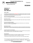
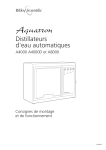
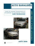
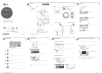
Merit
W4000 & W4000/EURO Water Still
Assembly and Operating Instructions
1
Issue 2
Fig. 1
Merit W4000 & W4000/EURO Water Still
2
Issue 2
Before Use
If the equipment is not used in the manner described in this manual the
protection provided by the equipment may be impaired.
N.B. The Merit Water Still is classified as ‘Permanently Connected Equipment’
and should be connected to the electricity supply by a qualified electrician in
the manner described in the electrical installation section of this manual.
The Merit Water Still is designed to operate under the following conditions:
-
For indoor use
Ambient temperature range +5°C to +40°C
Altitude up to 2000m
Relative humidity not exceeding 80%
Mains supply voltage fluctuations not greater than ±10% of nominal
Overvoltage category II IEC60364-4-443
Pollution degree 2 IEC664
3
Issue 2
Issue
1
2
Date
February 2014
December 2014
Reason
Initial Issue
Addition of thermostat reset button photos
Contents
Location
p.5
Assembly
p.6
Electrical Installation
p.10
Operation
p.11
Safety Cut-Outs
p.12
Care and Maintenance
p.14
Cleaning
p.14
Spares
p.16
Warranty
p.16
Fault Finding
p.17
4
Issue 2
Location
The Merit Water Still can be wall or bench mounted. Select a convenient location
which has access to the following services:
Electrical Supply
Before connection please ensure that the line supply is suitable. The Merit Water Still
is available in two models, model no. W4000 for supplies rated at 3kW, 220-240V
50/60 Hz single phase and model no. W4000/EURO for supplies rated at 3kW, 200240V, 50/60 Hz, single phase. Supplies should be fitted with a 30mA RCD circuit
breaker.
Water Supply
A cold water supply capable of providing a minimum flow rate of 60 l/hr. Ensure all
water supplies are earth bonded.
Drain
A waste water drain located below the level of the still so that the drain pipe can fall
away straight without kinks or bends, to allow an unimpeded flow. Ensure all
drainage systems are earth bonded.
Reservoir
A distillate collection reservoir should be located beneath the still.
5
Issue 2
Assembly
Your Merit W4000 has been designed with ease of assembly specifically in mind.
Before commencing assembly please study the illustrations and text to familiarise
yourself with the general layout. During assembly, follow the sequence of
instructions and do not connect the mains electricity supply until directed.
1.
Unpack the Still and identify the following components:
Qty. Component
Catalogue No.
1.
1.
1.
1.
Boiler Stand with 2 Boiler Straps
Boiler
Condenser
Heater
1.
1.
Hose Kit
Gasket Kit
I/W4000/S
I/W4000/B
I/WC48/M2/1
700692(ES) for W4000
700693(ES) for W4000/EURO
I/W4000/HK
I/MERIT/GK
2.
Take the metal stand and place in the desired location. Note that 2 screw
holes are provided for wall mounting.
3.
Take the boiler (W4000/B), the heater (700692(ES)) and the gasket kit
(I/MERIT/GK) and assemble as shown in Fig. 2 and the following:
i.
Place the bolts through the metal flange in the manner shown and then
place the metal flange over the tapered glass tube of the boiler.
ii.
Take the plastic insert and bend it round the tapered glass tube of the
boiler and into the metal flange. Pull the flange and insert towards the
open end of the tapered glass tube until the insert presses on the
glass.
iii.
Place the rubber gasket over the heater coils.
6
Issue 2
Boiler
Heater
Screw
Rubber
Gasket
Metal Flange
Plastic Insert
Fig. 2
iv.
Insert the heating element through the tapered glass tube and into the
boiler.
v.
Insert the three bolts into the threaded holes in the heater and
evenly tighten as Fig. 3. Do not over tighten.
Fig. 3
7
Issue 2
4.
Connect the springs of the 2 metal straps to the rear of the cradles.
5.
Feed the heater electric cable through the hole in the base of the support
stand. Place the boiler and heater assembly in the cradle of the stand. Ensure the
stop cock on the boiler is facing the front. Attach the free ends of the metal straps to
the front of the cradles to secure the boiler in place as Fig. 1.
6.
Close the stop cock and remove any covers off the boiler.
7.
Ensure the Sealing O Ring and Stabilising O Ring are correctly positioned, as
shown in Fig. 4.
Distillate
Outlet
Fig. 4
8.
Fit the condenser distillate outlet tubing and tie strap (not included).
9.
Fit the condenser by mounting it onto the vapour tube of the boiler. Ensure the
distillate outlet tube of the condenser faces the front and the cooling water outlet
faces parallel to the unit as Fig. 4. When resistance is felt, push down slightly to
create a seal until there is approximately a 5 – 10mm gap between the condenser
and the boiler.
8
Issue 2
10.
From the hose kit take the length of 8mm bore hose fitted with the plastic
screw thread connectors at either end. Referring to Fig. 1, screw one end of the hose
to the condenser outlet (upper) and the other end to the glass thread on the constant
level control.
11.
Fit the spare connector to the condenser inlet connection (lower). This is to
allow connection to the water supply. Use suitable, good quality tubing and hose
clips (Not included).
12.
Take the 1m length of 16mm tubing from the hose kit. Insert the end in hot
water to make it more supple. Attach to the drain/outlet of the constant level control.
Secure with the tie strap provided. Ensure the tubing falls away from the still with no
kinks or bends to impede water flow.
13.
Turn on the water supply and check for leaks.
14.
Carry out the electrical installation.
9
Issue 2
Electrical Installation
The electrical Installation should be carried out by a qualified electrician. The
following method is recommended.
The earthed spigots should pass a high current (i.e. >200mA) earth continuity test.
The equipment is supplied with a 1.7m of flexible triple core circular cable to CMA
3183 TQ specification. The conductors are 1.5mm² to BS 6360 Class 5 insulated
with E.P.R. The outer sheath is 85°C heat resisting type C.S.P. to HOFR, BS 6500
Table 9.
Connection to the mains electrical supply should be via a double pole 30mA RCD
isolation circuit breaker with a continuous current carrying capacity of 15A at 250V
and overcurrent protection of 15A, 250V.
These devices should be sited near to the equipment and be clearly marked
“Disconnect device for ‘Merit’ Water Still’.
Connect to the line supply noting that the wires in the instrument lead are coloured in
accordance with the following code:
Blue – Neutral
Brown – Live
Green & Yellow – Earth
Main Cable Replacement
If the mains cable requires replacement, only specially prepared spare mains lead
obtained from Bibby Scientific should be used.
Hot Warning!
10
Issue 2
Operation
1.
Turn on the cold water supply and adjust the flow to approximately 60 l/hr.
Note: It is strongly recommended to measure the flow rate, failure to do so can
result in possible injury from hot water exiting from the Still. If a flow meter
isn’t available, a simple measurement can be performed with a 1l beaker. Over
a timed period of five minutes the breaker should be completely filled five
times.
Observe that the water flows via the condenser and into the boiler. Wait until the
boiler has attained its correct operating level and make sure that the excess water is
flowing to drain.
2.
Switch on the electricity supply to the heating element at the mains isolation
switch.
For the W4000/EURO version, switch on the switch situated on the heater.
3.
After a few minutes the water will start to boil and distillate will emerge from
the condenser. With new glassware, or after cleaning, it is advisable to allow this to
run to drain for approximately 30 minutes before beginning collection.
4.
To turn off the still, first turn off the heating element but allow cooling water to
continue for a further 10 minutes to allow the still to cool.
Warning!
Do not use this equipment to distil any liquid other than water.
11
Issue 2
Safety Cut-Outs
The Merit Water Still is protected by two safety cut-outs:
After operation of either of the thermostats, normal operation may be resumed by
resetting the thermostats by means of their respective reset buttons mounted on the
end of the heater end cover.
Remove the black plastic cover and then press the button – a slight click will be
heard if the thermostat had operated.
To reset the thermostats the black covers need to be screwed off
12
Issue 2
Both Thermostats have tripped
The left hand thermostat has been reset
If the thermostats continue to operate, consult a qualified electrician or the Technical
Service Department of Bibby Scientific Ltd.
13
Issue 2
Care and Maintenance
N.B. Before commencing any maintenance, cleaning or fault finding the
equipment should be isolated from the mains electricity supply. These
operations should only be carried out by suitably qualified personnel.
Only spare parts supplied or approved by Bibby Scientific Ltd or its agent should be
used. Fitting of non-approved parts may affect the performance or safety of the
equipment.
Due to the nature of these parts it is necessary to periodically check the quality of the
plastic connectors and hoses. There should be no strain on the connectors or hoses.
Both the hoses and connectors should be intact without any cracking. If any damage
is discovered on these parts the Still should immediately be turned off, as detailed
under the ‘Operation’ section of this manual, and not used again before these parts
are replaced. Please refer to the ‘List of Spare Parts’ section of this manual for order
codes.
Cleaning
Over a period of operation, scale will build up inside the boiler. To obtain optimum
performance this scale should be removed on a regular basis.
The time span between cleaning depends greatly on the hardness of the water
supply and the amount of use. Frequently used stills in hard water areas may need
descaling once a week whereas in a soft water area several weeks may elapse
before descaling is necessary.
N.B. Heavy scaling will reduce distilled water quality and can shorten the life of
the heating element.
It is possible to descale the Merit Water Still without dismantling the glassware by
following these instructions in conjunction with Control of Substances Hazardous to
Health regulations (COSHH) 1988.
1.
Switch off the electricity supply to the still and allow it to cool
completely.
2.
Turn off the cooling water supply.
3.
Open the stop cock on the constant level control and allow the boiler to
drain completely. Close the stop cock.
4.
Turn on the cooling water supply and allow the boiler to fill to
approximately half way to its normal operating level. Turn off the water
supply.
14
Issue 2
5.
Into the open funnel of the constant level control, carefully add about
1 litre of 10% formic acid or kettle descaler. Do not use strong acids such as
hydrochloric, this can cause severe corrosion of the metal heating element.
Warning!
Always handle acids with great care. Protective clothing, gloves
and face masks should be worn during the descaling operation. Remove
any acid spills immediately.
Turn on the water supply and fill the boiler to the normal operating
level. The water will flush the acid into the boiler. The water supply
should be turned off when the level in the boiler is slightly below the
overflow.
6.
Leave the acid in the boiler to dissolve the scale. This may take some
time depending on the severity of the build-up.
7.
Open the stop cock and allow the boiler to drain:
Note: If the acid in the boiler has not been completely neutralised
the liquid flowing to drain may be highly acidic. All necessary
safety precautions should be observed around the drain and any
effluent control procedures followed.
8.
Close the stop cock, turn on the water and allow the boiler to fill with
cold water. Turn off the water, re-open the stop cock and allow the
boiler to drain.
Repeat this procedure three times.
9.
The Merit Water Still may now be restarted by referring to the
instructions given under ‘Operation’ in this manual.
Note: The stand and outer surfaces of the glassware should be cleaned using a
damp cloth and a mild detergent solution.
15
Issue 2
Spares
Boiler
W4000/B
Condenser
WC48/M2
Heater (Complete With Thermostats) (W4000) 240V A6/6
Heater (Complete With Thermostats) (W4000) 220V A6/6/EURO
Hose Kit
W4000/HK
Gasket Kit
W4000/GK
Stop Cock Assembly
A4000/RCOCK
Vapour Tube Sealing O Ring (Upper)
WB48/01
Vapour Tube Stabilising O Ring (Lower)
I/QR38/24
Heater Rubber Gasket
700449
Heater Element Plastic Insert
700450
Warranty
Bibby Scientific Ltd warrants this instrument to be free from defects in material and
workmanship, when used under normal laboratory conditions, for a period of three
(3) years. In the event of a justified claim, Bibby Scientific will replace any defective
component or replace the unit free of charge.
This warranty does NOT apply if damage is caused by fire, accident, misuse,
neglect, incorrect adjustment or repair, damage caused by incorrect installation,
adaptation, modification, fitting of non-approved parts or repair by unauthorised
personnel.
This warranty does not include the heater element which is only guaranteed for up to
1000 hours in use.
16
Issue 2
Fault Finding
In the event of operating difficulties with your Merit Water Still, please consult the
following notes. If these fail to identify and remedy the fault you are advised to
contact your supplier or the Technical Service Department of Bibby Scientific Ltd.
Note – Fault Finding should only be carried out by suitably qualified people.
Symptom
Cause
Remedy
Heater not working
a. Burnt out heater
b. Failed electricity supply
c. Thermostat
Water level in boiler is too low –
heater exposed
a. Supply of cooling water is
insufficient
b. Boiler drain stop cock left
open
a. Flow of cooling water is too
high
b. Drain is restricted
Replace heater.
Restore supply.
Identify and rectify the cause
and reset thermostat.
Adjust the supply to
approximately 60 l/hr.
Close stop cock.
Water level in boiler is too high
– e.g. water surging into
condenser
Distillate temperature is too high
– e.g. >50°C
Water in boiler is ‘pumped’ out
of the boiler to drain
Distillate quality is poor∗
Output less than 4 l/hr
Persistent tripping of the RCD
Supply of cooling water is
insufficient
a. Tubing from condenser
distillate outlet to the
reservoir is constricted
b. Mounting for condenser
thermostat is blocked
c. Supply of cooling water is
insufficient
Boiler heavily scaled
a. Mains electricity supply below
nominal voltage
b. Excessive cooling water flow
If integrity of the heater is
suspect
If integrity of the RCD is suspect
Adjust the supply to
approximately 60 l/hr.
Ensure drain pipe falls freely
from Still with no kinks.
Adjust the supply to
approximately 60 l/hr.
Ensure tubing falls freely from
Still with no kinks.
Remove obstruction.
Adjust the supply to
approximately 60 l/hr.
Clean boiler
Reduce to 60 litres/hr.
Replace Heater
Replace RCD
∗ Distillate quality when measured by pH or conductivity is greatly affected by
temperature and the presence of absorbed carbon dioxide.
17
Issue 2
18
Issue 2
Notes
19
Issue 2
20
Issue 2