1
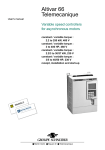
Altivar 66
Telemecanique
Guide d'exploitation
User's manual
variateurs de vitesse
pour moteurs asynchrones,
contrôle vectoriel de flux
avec capteur.
variable speed controllers
for asynchronous motors,
flux vector control with sensor.
2,2 / 220 kW, 400 V
3 / 350 HP, 460 V
■ Merlin Gerin ■ Modicon ■ Square D ■ Telemecanique
Altivar 66
Variateurs de vitesse pour moteurs asynchrones,
contrôle vectoriel de flux avec capteur
Variable speed controllers for asynchronous motors,
flux vector control with sensor
Page 2
F
R
A
N
Ç
A
I
S
Page 48
E
N
G
L
I
S
H
1
When the speed controller power supply is switched on, the power units as well as a certain
number of control components are connected to the AC supply. Contact with these parts is
extremely dangerous.
ATTENTION
After switching off the Altivar, wait 1 minute before performing any operation inside the
controller. This period corresponds to the time for the discharge of the capacitors.
During operation the motor can be stopped by cancelling the run command or the speed
reference, while the speed controller remains energized. If it is necessary to prevent restarting
for personnel safety reasons, this electronic interlock is insufficient. Provision must be made for
the disconnection of the power circuit.
E
N
G
L
I
S
H
The speed controller includes safety devices which, in the event of a fault, can cause the stopping
of the controller, and hence the motor. The motor itself can also be subject to stoppage by
mechanical jamming. Finally, voltage fluctuations, and power supply failures in particular, can
also cause the motor to stop.
NOTE
The clearance of the fault causing the stoppage can initiate a restart involving a hazard for certain
types of machines or installations, especially those which must conform to specific safety
regulations.
It is therefore important that in such cases the user should take appropriate steps to prevent such
restarting. For example by the use of an underspeed detector, causing the disconnection of the
speed controller power supply in the event of a non-programmed motor stoppage.
Equipment design must conform to specifications set out in the IEC standards.
As a general rule, the speed controller power supply must always be switched off before
performing any operation on either the electrical or the mechanical parts of the installation.
The company reserves the right to change the characteristics of its products and services at any
time to incorporate the latest technological developments. The information contained in this
document is therefore subject to change without notice and cannot be construed as containing
any form of contractual obligation.
48
Warning
The Altivar 66 must be considered as a component. It is neither a machine nor a device ready for
use in accordance with European standards (EN 60204-1 on the safety of machines, EN 50081 and
82 on electromagnetic compatibility). It is the responsiblity of the end user to ensure that his
machine conforms to these standards.
This speed controllers must be installed and implemented in compliance with the international and
national standards in force in the premises where it is to be used. Conformity is under the
responsibility of the integrator who will comply with the EMC directive, among others, for what
concerns the European Community.
Compliance with the essential requirements specified in the EMC directive is namely conditioned
by application of the prescriptions provided in our catalogue which indicates the accessories to
be associated with variators, for instance when radio disturbance filtering is needed.
For any information about these documents, please contact our SCHNEIDER
commercial agency.
49
E
N
G
L
I
S
H
E
N
G
L
I
S
H
50
Contents
Preliminary checks
Motor-speed controller combination
52
53 to 55
Controller / encoder combination
56
Available torque
57
Characteristics
58 and 59
Dimensions
60 to 62
Mounting recommendations
63 to 65
Mounting in a wall-fixing or floor-standing enclosure
66 to 68
Connection
Access to terminal blocks (sizes 1 to 5)
69
Power terminal blocks (sizes 1 to 5)
70
Access to terminal blocks (size 6)
71
Power terminal blocks (size 6)
72
Access to terminal blocks (size 7)
73
Power terminal blocks (size 7)
74
Control terminal blocks
75
Connection terminal blocks
Connection diagrams
Ferrite core installation and recommendations
76 and 77
78 to 80
81 and 82
Command type
83
Cable cross-sections
84
Cable entry points
Operating assistance
Maintenance assistance
Separate Spare parts
85 to 87
88
89 and 90
91 to 94
51
E
N
G
L
I
S
H
Preliminary checks
Receipt
Check that the speed controller reference code printed on the label is that same as that on
the delivery note corresponding to the purchase order.
Open the packaging and check that the Altivar 66 has not been damaged during transport.
Handling and storage
To ensure that the speed controller is protected prior to installation, handle and store it in
its packaging.
Handling prior to installation
The Altivar 66 400-460 V range consists of 19 models divided into 7 sizes.
Sizes 1 to 4 can be removed from their packaging and installed manually.
From size 5 upwards, a hoist must be used.
E
N
G
L
I
S
H
45°
maxi
Sizes 5 and 6
Size 7
52
Motor-speed controller combination
Preliminary comments
Motor power rating
In the tables on pages 54 and 55, the values given are the standard power ratings.
At 460 V - 60 Hz, the HP ratings conform to NEC (National Electrical Code).
There is no HP equivalent on a 460 V supply for a motor rated at 3 kW on a 400 V AC supply, while
the ATV-66U54N4 speed controller can be supplied at 460 V - 60 Hz.
Line current
The line current corresponds to the current consumed by the speed controller at nominal operating
power on an AC supply with an impedance to limit the presumed short-circuit current to :
– 22000 A for a 400 V - 50 Hz supply voltage,
– 65000 A for a 460 V - 60 Hz supply voltage.
Providing the supply via a power transformer suitable for the speed controller, or adding a line
choke from the catalogue, reduces current consumption to a value close to the speed controller
nominal current.
Example : ATV-66FD23N4 with 15 kW motor on a 400 V AC supply.
Constant torque application : Inv = 33 A.
Line current with no choke : 45 A.
Line current with choke from catalogue : 28 A.
ATV-66FU41N4 speed controller
When a speed controller is used with a motor whose power rating is below 2.2 kW, the speed
controller should be reconfigured via the graphic terminal to adapt its integral thermal protection
(see the Programming Manual).
53
E
N
G
L
I
S
H
Motor-speed controller combination
Constant torque applications (switching frequency 4 kHz)
Supply voltage : 400 V ± 15 % and 460 V ± 15 %, 50 Hz ± 5 % or 60 Hz ± 5 %
Speed controller
Motor power rating
Controller
nominal
current
(Inv)
Controller
maximum
transient
current
(60 s)
Total
power
dissipated
at nominal
load
Power
400 V
50 Hz
460 V
60 Hz
kVA
kW
HP
A
A
A
0.75
–
4
2.3
3.2
100
(see preceding
–
1
3.5
1.8
2.7
95
page)
1.5
–
6.5
4.1
5.6
123
–
2
6
3.4
5.1
117
2.2
–
9
5.8
8
146
–
3
9
4.8
7.2
140
ATV-66FU54N4 5.4
3
–
12
7.8
10.7
173
ATV-66FU72N4 7.2
4
–
15
10.5
14.3
209
–
5
13
7.6
11.4
195
5.5
–
20
13
17.7
251
–
7.5
18
11
16.5
225
7.5
–
26
17.6
24
317
–
10
24
14
21
290
11
–
35
24.2
33
447
–
15
34
21
31.5
380
15
–
45
33
45
580
–
20
44
27
40.5
530
22
–
60
48.4
66
754
–
30
59
40
60
655
30
–
78
66
90
1060
–
40
75
52
78
880
Reference
ATV-66FU41N4 4.1
E
N
G
L
I
S
H
Line
current
ATV-66FU90N4 9
ATV-66FD12N4 12
ATV-66FD16N4 16
ATV-66FD23N4 23
ATV-66FD33N4 33
ATV-66FD46N4 46
54
W
Motor-speed controller combination
Constant torque applications (switching frequency 2 kHz)
Supply voltage : 400 V ± 15 % and 460 V ± 15 %, 50 Hz ± 5 % or 60 Hz ± 5 %
Speed controller
Reference
Motor power rating
Line
current
Controller
nominal
current
(Inv)
Controller
maximum
transient
current
(60 s)
Total
power
dissipated
at nominal
load
Power
400 V
50 Hz
460 V
60 Hz
kVA
kW
HP
A
A
A
37
–
94
79.2
108
1159
–
50
92
65
97.5
885
45
–
110
93.5
127.5
1374
–
60
105
77
115.5
1055
55
–
130
115.5
157.5
1610
–
75
128
96
144
1270
75
–
171
151.8
207
2175
–
100
173
124
186
1605
90
–
198
190
258
2525
–
125
211
156
234
1955
110
–
237
226
307.5
3000
–
150
246
180
270
2255
132
–
275
270
367.5
3500
–
200
314
240
360
3070
160
–
326
330
450
4485
–
250
379
300
450
4485
200
–
399
407
555
5250
–
300
441
360
540
5250
220
–
421
448.8
612
5970
–
350
506
420
630
5970
ATV-66FD54N4 54
ATV-66FD64N4 64
ATV-66FD79N4 79
ATV-66FC10N4 100
ATV-66FC13N4 130
ATV-66FC15N4 150
ATV-66FC19N4 190
ATV-66FC23N4 230
ATV-66FC28N4 280
ATV-66FC31N4 310
W
E
N
G
L
I
S
H
55
Controller / encoder combination
Encoder interface board
The Altivar 66 is fitted with an encoder interface board VW3-A66203 with RS 422 encoder feedback
and 5 Vdc power supply.
The encoder interface board has :
• 3 logic inputs,
• 1 differential analog input,
• 1 analog current input,
• 2 open-collectors logic outputs,
• 1 analog output.
At the top of the encoder interface board, there is a PCMCIA slot for a board which interconnects
the controller to field bus, such as UNITELWAY, FIPIO, Interbus S, Modbus Plus.
Protection IP 20.
All the data related to the environment are the same as those of the Altivar 66.
Remark : The absence of the encoder interface board results in an "encoder card" fault.
Encoder type
This is incremental optical encoder with 5 V differential inputs,compatible with the RS 422
standard.The number of points per revolution should be between 90 and 5000.
Our proposal is 1024 (factory presetting).
E
N
G
L
I
S
H
Terminal
1
2
3
4
5
Signal
A+
A-
B+
B-
+ Vcc
6
7
8
9
Gnd
NC
It is indispensable to adapt the line by connecting resistors, such as those shown below, in the
differential channels as close as possible to the speed controller. The value of these resistors must
be between 100 and 150 Ohms (typically 120 Ohms).
In cases where the speed controller is installed coupled to an axis control module, it is unnecessary
to fit resistors as the axis module is normally of low impedance (90 to 370 Ohms).
The encoder and line resistors must not consume more than 225 mA.
Cable type
Use a cable containing screened twisted pairs.
Convey both complementary signals through the same screened conductor pair :
A +, A B +, B Vcc, Gnd
Screening should be electrically continuous from the motor to the controller.
Ensure electrical continuity when assembling the connector both motor and controller.
In case of a long length of cable (between 50 and 200 m), the size of wires on the encoder output
must be 2.5 mm2 ; beyond 200 m add an independant power supply.
56
Available torque
Continuous operation
For naturally ventilated motors, motor cooling is linked to speed. This leads to derating for speeds
which are below half the nominal speed.
Transient operation
The overtorque depends on the maximum transient current which the speed controller can supply.
On starting : up to 2 In for 0.2 s
Overspeed operation
The voltage can no longer develop in line with the frequency, leading to a decrease in motor
induction which results in a loss of torque. Check with the manufacturer that the motor can operate
at overspeed.
Constant torque applications : torque characteristics
T/Tn
1,7
3
1 Continuous useful torque : naturally ventilated
motor
1,2
2 Continuous useful torque : force-ventilated
motor
1
0,95
2
1
3 Transient overtorque : typical curve at ± 10 %
Value : 1.7 Tn for 60 s
0,5
0
1
25
30
50
60
N (Hz)
Note : the nominal frequency and the maximum frequency can be adjusted using the terminal, both
in open loop and close loop :
• from 25 to 200 Hz for ATV-66FU41N4 to FC31N4 controllers.
57
E
N
G
L
I
S
H
Characteristics
E
N
G
L
I
S
H
Output voltage
Maximum voltage equal to that of AC supply voltage
Frequency range
0.1 to 50/60 Hz
Extension possible :
– up to 200 Hz
Frequency resolution
0.05 Hz with analog reference signal at 50 Hz (10 bits)
0.015 Hz with digital reference signal at 50 Hz (12 bits + sign)
Speed control accuracy
0.01 % if HSP = LSP or by the line
0.2 % of analog input set-point
Acceleration and
deceleration ramps
Individually adjustable from 0.1 to 999.9 s (resolution 0.1 s)
Automatic adaptation of the ramp times in the event of the
torque capacity being exceeded
Main protective and safety
devices of the speed controller
Protection against short-circuits :
– between output phases
– between output phases and earth (ground)
– on internal supply outputs
– on logic and analog outputs
Thermal protection against overheating
AC supply overvoltage and undervoltage protection
Protection in the event of an AC supply phase fault
Motor protection
Integrated electronic thermal protection
(calculation of I2 t taking frequency into account)
Memorization of motor thermal state
Protection against phase faults
Degree of protection
IP 30 – NEMA type 1 cover closed, IP 20 cover open :
controllers ATV-66FU41N4 to 66FD79N4
IP 30 - NEMA type 1 cover closed, IP 00 cover open :
controllers ATV-66FC10N4 to 66FC19N4
IP00 - controllers ATV-66FC23N4 to 66FC31N4
Ambient air temperature
Operation : 0 °C to + 40 °C
ATV-66FU41N4 to FD79N4 :
operation possible up to + 60 °C with ventilation kit and
current derating of 2,2% per °C between + 40 °C and + 60 °C
Storage : - 25 °C to + 70 °C
58
Characteristics
Maximum operating altitude
1000 m without derating
(above this, derate the current by 1 % for each additional
100 m)
Maximum relative humidity
93 % without condensation or dripping water, conforming to
IEC 68-2-3
Degree of pollution
Degree 3 conforming to IEC 664-1
Vibration resistance
Conforming to IEC 68-2-6 :
– 1,5 mm peak to peak from 3 to 13 Hz– 1mm from 13 to
22.3 Hz and 2 gn from 22.3 to 150 Hz :
ATV-66FU41N4 to 66FD12N4
– 1.5 mm peak to peak from 3 to 13 Hz and 1 gn from 13 to
150 Hz : ATV-66FD16N4 to 66FD79N4 speed controllers
– 0.15 mm from 10 to 58 Hz and 1 gn from 58 to 150 Hz :
ATV-66FC10N4 to ATV-66FC19N4
Shock resistance
Conforming to IEC 68-2-27 : 15 g, 11 ms
E
N
G
L
I
S
H
59
Dimensions
4xØ
J
7,5
Sizes 1 to 3 : ATV-66FU41N4 to FD23N4
135
b
H
62
82,5
F1
F2
F3
7
8
9
4
5
6
ESC
1
2
3
ENT
0
.
a1
c
G
a
10
Sizes 4 and 5 : ATV-66FD33N4 to FD79N4
4xØ
J
E
N
G
L
I
S
H
135
b
H
62
82,5
F1 F2 F3
7
8
9
4
5
6
ESC
1
2
3
ENT
0
.
a1
c
60
G
a
Dimensions
10
Size 6 : ATV-66FC10N4 to FC19N4
J
4xØ
F1 F2 F3
7
8
9
4
5
6
ESC
1
2
3
ENT
0
.
b
H
a1
c
G
a
Size
Altivar reference
a
mm
b
mm
c
mm
G
mm
H
mm
J
mm
Ø
mm
a1
mm
Weight
kg
1
ATV-66FU41N4
ATV-66FU54N4
ATV-66FU72N4
200
295
165
175
280
35.4
5.5
6
4.7
2
ATV-66FU90N4
ATV-66FD12N4
234
325
195
209
310
44.3
5.5
6
7.3
3
ATV-66FD16N4
ATV-66FD23N4
234
415
245
209
400
79
5.5
6
14
4
ATV-66FD33N4
ATV-66FD46N4
240
600
280
205
580
116.4
7
12
27
5
ATV-66FD54N4
ATV-66FD64N4
ATV-66FD79N4
350
650
300
300
620
121.4
9
12
40
41
41
6
ATV-66FC10N4
ATV-66FC13N4
ATV-66FC15N4
ATV-66FC19N4
585
980
370
525
960
205
11
70
127
136
136
136
61
E
N
G
L
I
S
H
Dimensions
Size 7 : ATV-66FC23N4 to FC31N4
12,7
12,6
48
48
6 x Ø 9,5
L1
L2
L3
(OUT)
286
547
286
(IN)
W
F1 F2 F3
7
8
9
4
5
6
ESC
1
2
3
ENT
0
.
V
1127
U
403
517
120
28,5
E
N
G
L
I
S
H
960
49
507
200
4 x Ø 9,1
95
650
Bottom view
Weight : 255 kg
62
Mounting recommendations (sizes 1 to 5)
Install the device vertically.
Do not place it close to heating elements.
Leave sufficient clearance to allow circulation of air necessary for cooling. Ventilation is from the
bottom to the top of the device.
Sizes 4 and 5
≥ 200
Sizes 1 to 3
≥ 100
≥ 50
≥ 50
≥ 50
F1 F2 F3
7
8
9
4
5
6
ESC
1
2
3
ENT
0
.
≥ 50
F1
F2
F3
7
8
9
4
5
6
ESC
1
2
3
ENT
0
.
E
N
G
L
I
S
H
≥ 200
≥ 100
Ventilating fan flow rates
5 dm3/s
ATV-66FU41N4 and FU54N4 (size 1)
:
ATV-66FU72N4 (size 1)
: 10 dm3/s
ATV-66FU90N4 and FD12N4 (size 2)
: 22 dm3/s
ATV-66FD16N4 and FD23N4 (size 3)
: 47 dm3/s
ATV-66FD33N4 to FD79N4 (sizes 4 and 5)
: 100 dm3/s
63
Mounting recommendations (sizes 6 and 7)
Install the device vertically.
Do not place it close to heating elements.
Maintain enough clearance for the cooling air flow that a fan provides from bottom to top for Size 6
unit and from the bottom of the front panel to the top for Size 7 unit.
Sizes 7
Sizes 6
≥ 250
≥ 200
(IN)
L1
L2
L3
(OUT)
≥ 50
≥ 50
W
F1 F2 F3
7
8
9
4
5
6
ESC
1
2
3
ENT
0
.
V
U
≥ 50
E
N
G
L
I
S
H
≥ 50
≥ 350
≥ 200
Ventilating fan flow rates
ATV-66FC10N4 to FC19N4 (size 6) : 250 dm3/s
ATV-66FC23N4 to FC31N4 (size 7) : 470 dm3/s
Recommendation for installing a Size 7 unit in a cabinet : A clearance greater than 250 mm should
be provided between the VSC and the cabinet walls for easier routing of cables and easier access
to the unit.
64
Mounting recommendations (size 7)
Principle of forced-air cooling in IP 00
11
91
,
Air outlet opening, power section
686
Air outlet, power section
470 dm3/s
F1 F2 F3
7
8
9
4
5
6
ESC
1
2
3
ENT
0
.
3 x 50 dm3/s
403
Board cooling
fan
E
N
G
L
I
S
H
470 dm3/s
21
786
21
11
107
Air inlet opening, power section
15
Air inlet,
power section
Recommendation : Hot air must be exhausted to the outside.
The IP00 version of the Altivar 66 Size 7 unit must be equipped with a protective barrier to
ensure personnel safety against electric shocks.
65
Mounting in a wall-fixing or floor-standing enclosure
Metal enclosure, degree of protection IP 23 or IP 54
Observe the mounting recommendations given on pages 63 to 65.
To ensure adequate air circulation
inside the speed controller :
– provide ventilation louvres,
– check that the ventilation is
adequate. If not fit a forced
ventilation unit with a filter,
–use special filters at IP 54.
θ°
40 °C
θ°
40 °C
Dust and damp proof metal enclosure (degree of protection IP 54)
Under certain environmental conditions the speed controller must be mounted in a dust and damp
proof enclosure : dust, corrosive gas, high humidity with a risk of condensation or dripping water,
splashing liquid, etc.
Observe the mounting recommendations given on pages 63 to 65.
To avoid hot spots in the speed controller, add a ventilation kit to circulate the air inside the device.
This arrangement makes it possible to use the speed controller in an enclosure whose maximum
internal temperature can reach 60 °C.
Warning
In this case, derate the speed controller nominal current by 2.2 % for each °C above 40 °C.
Ventilation kit references : VW3-A66821 for
VW3-A66822 for
VW3-A66824 for
VW3-A66825 for
E
N
G
L
I
S
H
ATV-66FU41N4 to FU72N4 (size 1)
ATV-66FU90N4 to FD23N4 (sizes 2 and 3)
ATV-66FD33N4 to FD46N4 (size 4)
ATV-66FD54N4 to FD79N4 (size 5)
Calculating the size of the enclosure
Maximum thermal resistance Rth (°C/W) :
Rth = θ° - θ°e
P
θ° = maximum temperature in the enclosure in °C,
θ°e = maximum external temperature in °C,
P = total power dissipated in the enclosure in W.
Power dissipated by the speed controller : see pages 54 and 55.
Add the power dissipated by the other component parts of the device.
Useful heat exchange surface of the enclosure S (m2) :
(sides + upper surface + front panel, when wall mounted)
S= K
K = thermal resistance per m2 of enclosure.
Rth
For a metal enclosure : K = 0.12 with internal fan,
K = 0.15 with no fan.
Warning : do not use insulated enclosures, as they have a poor level of conductivity.
66
Mounting in a wall-fixing or floor-standing enclosure
Flush mounting (sizes 1 to 3)
To reduce the power dissipated in the enclosure, the speed controller can be flush mounted, with
the heatsink on the outside. This necessitates making a cut-out in the rear of the enclosure and
using a mounting kit which comprises : dust and damp proof gaskets, leaflet and a cut-out drawing.
IP 54 kit references : VW3-A66801 for ATV-66FU41N4 to FU72N4 (size 1)
VW3-A66802 for ATV-66FU90N4 and FD12N4 (size 2)
VW3-A66803 for ATV-66FD16N4 and FD23N4 (size 3)
Mounting as an air heat exchanger with the exterior (sizes 1 to 5)
To reduce the power dissipated in the enclosure, the speed controller can be fitted with adaptors
which enable the ventilation fan to draw in cool air at the bottom of the controller and evacuate
hot air at the top.
This necessitates making a two cut-outs in the rear of the enclosure and using a mounting kit
which comprises : adaptors, dust and damp proof gaskets, leaflet and a cut-out drawing.
Kit references :
VW3-A66811 for
VW3-A66812 for
VW3-A66813 for
VW3-A66814 for
VW3-A66814 for
ATV-66FU41N4 to FU72N4 (size 1)
ATV-66FU90N4 and FD12N4 (size 2)
ATV-66FD16N4 and FD23N4 (size 3)
ATV-66FD33N4 and FD46N4 (size 4)
ATV-66FD54N4 to FD79N4 (size 5)
With each of these mounting methods, the maximum internal temperature in the enclosure can
reach 60 °C without having to derate the speed controller current. To avoid hot spots, use the
ventilation kit to circulate the air inside the speed controller.
Note : with each of these mounting methods, the heatsink and ventilation fan outside the enclosure
remains protected to IP 30.
E
N
G
L
I
S
H
67
Mounting in a wall-fixing or floor-standing enclosure
Power dissipated by the speed controller in the enclosure using one of the mounting methods
Altivar reference
ATV-66FU41N4
ATV-66FU54N4
ATV-66FU72N4
ATV-66FU90N4
ATV-66FD12N4
ATV-66FD16N4
Power in W
70
70
70
75
75
110
Altivar reference
ATV-66FD23N4
ATV-66FD33N4
ATV-66FD46N4
ATV-66FD54N4
ATV-66FD64N4
ATV-66FD79N4
Power in W
130
130
145
198
200
210
Possibility of condensation
If the device is left switched off for long periods, a heating system must be provided (0.2 to 0.5 W per
10 cm2 of the enclosure) which switches on automatically as soon as the device stops.
This device keeps the inside of the enclosure at a temperature slightly above the external
temperature, and avoids any risk of condensation or dripping water while the device is switched off.
Alternative solution : keep the device powered up when it is stopped (the heat of the device itself
when it is powered up is generally sufficient to provide this difference in temperature).
E
N
G
L
I
S
H
68
Access to terminal blocks (sizes 1 to 5)
The protective cover is attached to the front panel of the Altivar in the following way :
– Sizes 1 to 3 : clip-on attachment,
– Sizes 4 and 5 : using 2 captive screws.
To access the terminal blocks, detach the cover and pivot it from right to left.
Location of the terminal blocks
Sizes 4 and 5
Sizes 1 to 3
J33
J34
J13
J32
J33
J34 J32
J12
J13
J12
d
J1
e
J2
E
N
G
L
I
S
H
g
f
b
J2
a
b
c
d
e
f
g
h
mm mm mm mm mm mm mm mm
h
T5
S5 200 320 90 100 60 220 60 170
a
J1
c
T4
S4 110 300 80 100 60 180 40 180
The connection cables enter through the base of the Altivar (see page 85 and 86) :
– sizes 1 to 3 : via holes which are fitted with cable glands in the insulating plate (attached with 2
screws), or via the opening created by the removal of this plate.
– sizes 4 and 5 : via holes which are fitted with cable glands in the metal plate or via the opening
created by the removal of this plate.
When the plate is removed the degree of protection of the speed controller becomes IP 20.
69
Power terminal blocks (sizes 1 to 5)
Terminal blocks
J13 : control card analog I/O.
J12 : control card logic I/O.
J1 : relay logic outputs.
J2 : power terminal block.
J2
Function
Maximum connection capacity
Terminaltightening torque
terminals
Size 1
Size 2
Size 3
Size 4
Size 5
S
sS
Earth (ground) terminal
connected to Altivar earth
6 mm2
1,96 Nm
6 mm2
1,96 Nm
10 mm2
2,5 Nm
35 mm2
4Nm
70 mm2
10 Nm
CL1
CL2
Control and ventilation
power supply
2.5 mm2
0,76 Nm
2.5 mm2
0,76 Nm
2.5 mm2
0,76 Nm
2.5 mm2
0,76 Nm
2.5 mm2
0,76 Nm
L1
L2
L3
Power supply
2.5 mm2
0,76 Nm
6 mm2
1,96 Nm
10 mm2
2,5 Nm
35 mm2
4 Nm
70 mm2
10 Nm
+
–
DC bus connection
2.5 mm2
0,76 Nm
6 mm2
1,96 Nm
10 mm2
2,5 Nm
35 mm2
4 Nm
70 mm2
10 Nm
PA
PB
Connection to the
braking resistor
2.5 mm2
0,76 Nm
6mm2
1,96 Nm
6 mm2
1,96 Nm
16 mm2
3 Nm
35 mm2
4 Nm
U/T1
V/T2
W/T3
Connection to the motor
2.5 mm2
0,76 Nm
6 mm2
1,96 Nm
10 mm2
2,5 Nm
35 mm2
4 Nm
70 mm2
10 Nm
Earth (ground) terminal
connected to Altivar earth
6 mm2
1,96 Nm
6 mm2
1,96 Nm
10 mm2
2,5 Nm
35 mm2
4 Nm
70 mm2
10 Nm
s
E
N
G
L
I
S
H
The Altivar is delivered in a configuration to ensure control of power by a circuit-breaker.
Terminals CL1-CL2 are connected to power supply L1-L2 via a strap.
Should the control power supply CL1-CL2 be supplied separately from the load power supply, it
is then better to remove the tow straps so as to facilitate connection at terminals CL1-CL2 (see
below).
– ATV-66FU41N4 to FD12N4 : Remove the straps between (CL1, CL2) and (L1, L2)
– ATV-66FD16N4 to FD79N4 : Remove the straps at terminals CL1-CL2.
Unscrew the top section and then pull out the strap, leaving
the bottom section simply plugged in.
Remark : For the ratings ATV-66FD33N4 to FD79N4, the control
power supply must always be present before the load power
supply (where this is separate). The variator must not be in the
following configuration : load power supply present,
control power supply absent.
Note : if the load and control power supplies come from two separate networks with a common
ground, make sure that the phases match between L1 and CL1, and between L2 and CL2.
70
Access to terminal blocks (size 6)
For size 6 Altivars, the metal protective cover on the front panel supports the graphic terminal and
the 3 LED indicators. It is attached via two captive screws.
To access the terminal blocks, unscrew the cover and pivot it from right to left. Before doing this,
read the instructions on the label on the right hand side of the speed controller.
Location of terminal blocks
J34
J32
J12
J33
J13
J1
100
190
380
30
E
N
G
L
I
S
H
520
170
40
580
J2
170
330
s
240
sÒ
180
J3
The connection cables enter through the base of the Altivar via holes which are fitted with cable
glands in the metal plate or via the opening created by the removal of this plate.
Inside the speed controller, there is a vertical insulating conduit on the right hand side to carry the
control and signalling circuit wires.
When the plate is removed the degree of protection of the speed controller becomes IP 00.
71
Power terminal blocks (size 6)
Terminal blocks
J13 : control card analog I/O.
J12 : control card logic I/O.
J1 : relay logic outputs.
J2 and J3 : power terminal blocks.
J2 - terminals
Function
Maximum connection capacity
Terminaltightening torque
ATV-66FC10N4
and FC13N4
ATV-66FC15N4
and FC19N4
L1
L2
L3
Power supply
120 mm2
36,7 Nm
185 mm2
36,7 Nm
+
–
DC bus connection
120 mm2
36,7 Nm
185 mm2
36,7 Nm
U/T1
V/T2
W/T3
Connection to the motor
120 mm2
36,7 Nm
185 mm2
36,7 Nm
PA
PB
Connection to the
braking resistor
50 mm2
5,6 Nm
50 mm2
5,6 Nm
CL1
CL2
Control and ventilation
power supply
4 mm2
2,3 Nm
4 mm2
2,3 Nm
CL21
CL22
Terminals
power supply/control
4 mm2
2,3 Nm
4 mm2
2,3 Nm
s
Earth (ground) terminals
connected to Altivar earth
70 mm2
10 Nm
95 mm2
10 Nm
J3 - terminals
E
N
G
L
I
S
H
The Altivar is delivered in a configuration to ensure control of power by a circuit-breaker.
Terminals CL1-CL2 are connected to power supply L1-L2 via a strap.
Should the control power supply CL1-CL2 be supplied separately from the load power supply, it
is then better to remove the tow straps so as to facilitate connection at terminals CL1-CL2.
– ATV-66FC10N4 to FC19N4 : Remove the straps between (CL1, CL2) and (CL21, CL22)
Remark : For the ratings ATV-66FC10N4 to FC19N4, the control power supply must always
be present before the load power supply (where this is separate).
The variator must not be in the following configuration : load power supply present,
control power supply absent.
Note : if the load and control power supplies come from two separate networks with a common
ground, make sure that the phases match between L1 and CL1, and between L2 and CL2.
72
Access to terminal blocks (size 7)
The size 7 Altivars have no metal protecting cover on the front face (variator protection class IP 00).
The terminal and the 3 indicator LEDs are installed on the insulating ranck of the control card.
Location of terminal blocks
150
(In)
L1
PA
150
L2
410
(OUT)
L3
–
PB
+
150
340
CL1, CL2,
CL21, CL22
W
J13
1080
V
J32
U
J12
90
J1
E
N
G
L
I
S
H
555
520
80
(OUT)
80
550
950
950
1000
J34
J33
3xØ8
3 x Ø 10
73
Power terminal blocks (size 7)
Terminal blocks
J13 : control card analog I/O.
J12 : control card logic I/O.
J1 : relay logic outputs.
J2 - terminals
Function
Maximum connection capacity
Terminaltightening torque
ATV-66FC23N4 to FC31N4
E
N
G
L
I
S
H
L1
L2
L3
Power supply
3 x 240 mm2
36,5 Nm
+
–
DC bus connection
2 x 240 mm2
36,5 Nm
U/T1
V/T2
W/T3
Connection to the motor
3 x 240 mm2
36,5 Nm
CL1
CL2
Control and ventilation
power supply
4 mm2
2,3 Nm
PA
PB
Connection to the braking resistor
2 x 240 mm2
36,5 Nm
CL21
CL22
Terminals for common load/control
power supply
4 mm2
2,3 Nm
Earth (ground) terminals
connected to Altivar earth
3 x 185 mm2
18,5 Nm
s
The Altivar is delivered in a configuration to ensure control of power by a circuit-breaker.
Terminals CL1-CL2 are connected to power supply L1-L2 via a strap.
Should the control power supply CL1-CL2 be supplied separately from the load power supply, it
is then better to remove the tow straps so as to facilitate connection at terminals CL1-CL2 (see
below).
– ATV-66FC23N4 to FC31N4 : Remove the straps between (CL1, CL2) and (CL21, CL22)
Remark : For the gauges ATV-66FC23N4 to FC31N4, the control power supply must always be
present before the load power supply (where this is separate). The variator must
not be in the following configuration : load power supply present, control power supply absent.
Note : if the load and control power supplies come from two separate networks with a common
ground, make sure that the phases match between L1 and CL1, and between L2 and CL2.
74
Control terminal blocks
Terminal blocks J13, J12 and J1 have plug-in connectors with a coding chip.
Maximum connection capacity : 2.5 mm2.
Factory configuration of the speed controller
J13-J12
terminals
S
Function
Characteristics
Connection of screening to
reference circuits
Earth (ground) terminal connected to Altivar earth
Terminal not connected
COM
Analog input common
0V
AI1
Voltage speed reference
Analog input 0-10 V, impedance 30 kΩ
+10
Supply to speed reference
potentiometer R
+ 10 V isolated and regulated, maximum 10 mA,
recommended value of R between 1 kΩ and 10 kΩ
AI2
Current speed reference
Analog input 4-20 mA, impedance 250 Ω
AO1
AO2
Output frequency
Output current
2 analog outputs 0-20 mA, maximum
recommended load impedance 500 Ω
COM
Analog output common
0V
LI1
LI2
LI3
LI4
Unlock speed controller
Forward operation command
Reverse operation command
Step by step operation (JOG)
4 logic inputs, impedance 3.5 kΩ,
supply + 24 V (min 11 V, max 30 V),
state 0 if < 5 V, state 1 if ≥ 11 V
+24
Supply to logic inputs
+ 24 V isolated and not regulated (min 20 V,
max 30 V),
maximum 200 mA
LOP
Supply to logic outputs
Connect to + 24 V of internal supply
or of an external supply
LO1
LO2
Speed reached
Current limit reached
2 PLC compatible logic outputs (open collector),
+ 24 V (max 32 V), max 20 mA with internal supply
or 200 mA with external supply
COM
Logic output common
0V
R1A
R1B
R1C
C/O contact on relay R1 :
activated on power up,
de-activated at a fault
Switching capacity of contacts :
min 10 mA for 24 V DC, max for inductive
load (cos ϕ = 0.4 and L/R = 7 ms) : 1.5 A for
250 V AC or 2.5 A for 30 V DC
R2A
R2B
R2C
C/O contact on relay R2 :
not assigned
E
N
G
L
I
S
H
J1
terminals
75
Control terminal blocks
Encoder interface card VW3-A66203
Terminal blocks J32 and J33 are provided with plug-in type connectors.
Maximum connection capacity : 2.5 sq. MM with or without end-piece.
Terminal block J34 is a SUB-D-9-way socket connector for coder feedback.
Ex-works controller configuration
J33
Terminal
Function
Specifications
S
Set-point circuit screen connection
de l'Altivar
Earthing connector connected to
Altivar ground
COM
Analog I/O common
Non-connected terminal
AI3A
Speed set-point
AI3B
E
N
G
L
I
S
H
0V
± 10 V differential input, 30 kohm
impedance
+10
Analog input power supply
Maximum current flow : 10 mA
-10
Analog input power supply
Maximum current flow : 10 mA
AI4
Non-configured current analog input
0-20 mA, 4-20 mA, 20-4 mA, 4-12-20 mA
250 ohm impedance
AO3
Motor torque
0/4-20 mA, 4-12-20 mA
500 ohm maximum impedance
COM
Analog I/O common
0V
Remark : AI1 / AI2 / AI3 inputs are summing inputs.
J34
Terminal
Specifications
+5V
5
Coder power supply
Maximum current flow : 225 mA
B-
4
Incremental chanel B
Maximum frequency :
B+
3
A-
2
A+
1
9
Non-connected
COM
8
Coder output common
7
Non-connected
6
76
Function
≤ 240 kHz per chanel
Incremental chanel A
0V
Control terminal blocks
Encoder interface card VW3-A66203 (continued)
J32
Terminal
LI9
LI10
LI11
+ 24 (1)
LOP
Non-configured (ex-works)
LO3
LO4
Thermal level
Frequency level
COM
Logic I / O common
Function
Logic input power supply
Logic output power supply
Specifications
3 logic inputs with 3.5 khom impedance
24V power supply (11V min., 30V max.)
state 0 when V < 5V, state 1 when V ≥ 11V
(20V min., 30V max. ), 200 mA current flow
To be connected to the + 24V line of the internal
power supply unit or external power source
0V
(1) The 200 mA maximum current flow corresponds to the current consumption on the + 24 V line of
the control board and on the + 24 V line of flux vector control board.
It is necessary to ensure that the ground common mode voltage applied to the J32
and J13-12 terminals doesn't exceed the Extra Low Voltage (50 V AC or 120 V DC)
Encoder détermination : maximum number of pulses per mechanical revolution.
Np : maximum number of pulses per mechanical revolution,
Fs : maximum motor frequency,
p : number of pair poles,
Fmaxi by chanel = Np x Fs/p
- if Fs = 50 Hz, p = 2, Fmaxi = 240 kHz
Np = 9600 pulses/revolution
- if Fs = 200 Hz, p = 1, Fmaxi = 240 kHz
Np = 1200 pulses/revolution
E
N
G
L
I
S
H
Encoder connector pin arrangement (J34) :
1
A+
2
A-
3
B+
4
B-
5
Vcc
6
7
8
Gnd
9
NC
77
Connection diagrams
Encoder interface card VW3-A66203
Terminal J 33
AI4
- 10
+10
AI3B
AI3A
COM
AI4
- 10
+10
AI3B
AI3A
COM
S
S
Bipolar speed reference
with ± 10V external power supply
Bipolar speed reference
±10 V
R
–
E
N
G
L
I
S
H
R
–
+
4 - 12 - 20 mA
78
AI4
- 10
+10
AI3B
AI3A
COM
S
Current torque reference
0-20 mA
4-20 mA
20-4 mA
+
AI4
- 10
+10
AI3B
AI3A
COM
S
AI4
- 10
Current speed reference
+10
AI3B
AI3A
COM
S
Unipolar speed reference
Connection diagrams
Encoder interface card VW3-A66203
S
COM
AI3A
±10 V
AI3B
+10
- 10
AI4
AO3
COM
SUB-D
With connection to a 24Vdc external power source
LI9
LI9
LI10
LI10
LI11
LI11
+ 24
+ 24
LOP
+
LO3
E
N
G
L
I
S
H
LOP
LO3
24V
LO4
COM
LO4
–
COM
Wiring precautions
Separate the control lines from the power cables.
For the speed set-point lines, the use of a cable twisted at a pitch of 25-50 mm, or a screened cable
with the screen connected to terminal S is recommended.
79
Connection diagrams
With circuit-breaker
+
–
PA
Optional braking resistor
PB
Q1
L1
U/T1
U1
L2
V/T2
V1
L3
W/T3
W1
CL1
Optional
chokes
CL2
M1
3c
R1A
R1B
Other connections
S
COM
4-20 mA
COM
R2A
LO1
–
AI1
R
R1C
R2B
LO2
+
+10
R2C
LOP
AI2
COM
LI1
AO1
Hz
LI2
AO2
A
LI3
COM
LI1
LI4
LO1
LI2
+24
LO2
LI3
LOP
LI4
+
24 V
Unlock
Forward
E
N
G
L
I
S
H
Reverse
JOG
–
Terminal
connector
With contactor
Q1
KM1
U/T1
L2
V/T2
V1
W/T3
W1
L3
F2
U1
L1
M1
3 c
F1
CL1
CL2
Access to terminals CL1-CL2 : remove the 2 straps.When load power supply L1-L2-L3) is present
or when supplied by the DC bus (+, -), power supply CL1-CL2 must always be present.
80
Ferrite core installation and recommendations
Wiring precautions
Power
Respect the cable cross-sections recommended by the standards.
Speed controller-motor connection cables :
– minimum length : 0.5 m,
– maximum length 100 m with non-screened cables, or 50 m with screened cables.
Above this, install an L or LC filter between the speed controller and the motor (refer to the
catalogue).
The speed controller must be connected to earth (ground), in order to conform with the regulations
covering high leakage currents (above 3.5 mA). Use of a differential circuit-breaker upstream is not
recommended since DC components could be generated by leakage currents from the speed
controller. If the installation comprises several speed controllers on the same line, connect each
controller to earth separately. If necessary, install a line choke (refer to the catalogue).
Keep the power cables separate from the low level signal circuits in the installation (detectors,
PLCs, measuring apparatus, video, telephone).
Control
Keep the control circuits separate from the power cables. For the speed reference circuits, it is
recommended that twisted cable with a pitch of between 25 and 50 mm is used, or screened cable
with the screening connected to terminal S.
Ferrite core installation
J13
F1
F2
F3
7
8
9
4
5
6
ESC
1
2
3
ENT
0
.
The options to enable compliance with the EMC directive are those
indicated in our documentation (EMC Catalogue No. 75011). These
items need to be ordered separately.
The only items delivered with the product are :
– The control cable ferrite (blue) : "control ferrite core“.
– The motor cable ferrite (red) : "motor ferrite core“.
(1) motor cable
(2) control cable
J12
J1
J2
(2)
(1)
The ferrites must be installed on the unscreened cable as close as
possible to the terminals on the Altivar.
Please note : Schneider organisation is at your disposal to provide any assistance required in terms
of Documentation, Practical Advice, Technical Assistance, EMC Traning Courses.
Selection of associated components
Circuit-breaker or isolator Q1 (with gl type fuses) : determine according to the line current, plus
the consumption of the other parts of the device.
Contactor KM1 : select for category AC-1, according to the line current.
Fuses F1-F2 : determine according to the AC supply voltage and the rating of the control and
ventilation power supply transformer (terminals CL1-CL2) :
– ATV-66FU41N4 to FD23N4
(sizes 1 to 3) : 40 VA,
– ATV-66FD33N4 to FD79N4
(sizes 4 and 5) : 110 VA,
– ATV-66FC10N4 to FC19N4
(size 6)
: 630 VA,
– ATV-66FC23N4 to FC31N4
(size 7)
: 1000 VA.
81
E
N
G
L
I
S
H
Recommendations
Reassignment of I/O
The following I/O can be reassigned via the graphic terminal : logic inputs LI3 and LI4 or LI9 to LI11
logic outputs LO1 to LO4, relay output R2, and analog outputs AO1 and AO2.
The characteristics of current input AI2, AI4 and analog outputs AO1 to AO3 can also be modified
using the graphic terminal :
– input AI2 : 4-20 mA, 0-20 mA, 20-4 mA, X-20 mA (X programmable : resolution 0.1 mA),
– input AI4 : 4-20 mA, 0-20 mA, 20-4 mA, 4-12-20 mA,
– outputs AO1 and AO2 : 0-20 mA or 4-20 mA.
– output AO3 : 4-20 mA, 0-20 mA, 4-12-20 mA.
This is described in more detail in the Programming Manual.
A switch on the control card (to the left of terminal block J13) is used to convert input AI2 to a 0-5 V
reference input (after having configured it as 0-20 mA via the graphic terminal).
Minimum braking resistance values
Using a lower resistance value than the one given in the table below will cause the resistance
thermal protection to become inefficient. Use preferably the values given in the catalogue.
Reference
ATV-66FU41N4
ATV-66FU54N4
ATV-66FU72N4
ATV-66FU90N4
ATV-66FD12N4
ATV-66FD16N4
ATV-66FD23N4
ATV-66FD33N4
ATV-66FD46N4
ATV-66FD54N4
E
N
G
L
I
S
H
82
Min. value (Ω)
56
56
56
54
50
27
27
14
14
10
Reference
ATV-66FD64N4
ATV-66FD79N4
ATV-66FC10N4
ATV-66FC13N4
ATV-66FC15N4
ATV-66FC19N4
ATV-66FC23N4
ATV-66FC28N4
ATV-66FC31N4
Min. value (Ω)
5
5
2,5
2,5
2,5
2,5
2
1,25
1,25
Command type
2-wire command
2-wire command : logic states maintained (factory setting for the speed controller).
2-wire command
Input LI1 :
– change to state 1 : controller unlocked,
– change to state 0 : speed controller locked and "freewheel" stop of motor.
Unlock
LI1
Forward
LI2
Reverse
LI3
JOG
LI4
To stop the motor following the
deceleration ramp, inhibit the direction
command on the enabled input LI2 or
LI3.
Step by step function (JOG) : enable
input LI4 before unlocking using input
LI1, apply pulses to input LI2 or LI3
(direction of operation).
+24
– the first direction command selected takes priority over the other,
– if the two direction commands are enabled simultaneously, forward operation takes priority.
E
N
G
L
I
S
H
83
Cable cross-sections
Power cables to terminals L1-L2-L3 and U/T1-V/T2-W/T3
Altivar reference
Cable cross-section recommended by
IEC 947-1 standards
mm2
E
N
G
L
I
S
H
84
ATV-66FU41N4
2,5
ATV-66FU54N4
2,5
ATV-66FU72N4
2,5
ATV-66FU90N4
4
ATV-66FD12N4
6
ATV-66FD16N4
6
ATV-66FD23N4
10
ATV-66FD33N4
25
ATV-66FD46N4
35
ATV-66FD54N4
35
ATV-66FD64N4
50
ATV-66FD79N4
50
ATV-66FC10N4
95
ATV-66FC13N4
120
ATV-66FC15N4
185
ATV-66FC19N4
185
ATV-66FC23N4
150 x 2 (2 cables)
ATV-66FC28N4
185 x 2 (2 cables)
ATV-66FC31N4
185 x 2 (2 cables)
Cable entry points
= h =
View from below showing cable entry points
Sizes 1 to 3
d1
e
g
d2
f
f
d
Size
Altivar reference
d1
d2
d
e
f
g
h
1
ATV-66FU41N4 to
FU72N4
29
22
100
79
45
113
43
2
ATV-66FU90N4 &
FD12N4
29
29
117
106
58
134
58
3
ATV-66FD16N4 &
FD23N4
29
29
117
147
58
175
58
E
N
G
L
I
S
H
189,5
143,5
Size 4 ATV-66FD33N4 & FD46N4
115,5
111,5
76,5
68,5
43,5
(2) Ø 29
(1) Ø 37,5
30,5
(3) Ø 18
(4) Ø 16
(5) Ø 16
241
231
216
211
1 - Motor output
2 - PA / PB output
3 - Separate control power supply
4 - Option board
5 - Monitoring control
6 - Relay output
7 - Power supply
8 - + / - output
247
(6) Ø 20
(7) Ø 37,5
(8) Ø 37,5
85
Cable entry points
View from below showing cable entry points
Size 5 : ATV-66FD54N4 to FD79N4
305
248,5
192,5
191,5
151,5
150
91,5
49,5
(4) Ø 16
(2) Ø 37
(1) Ø 47,5
(5) Ø 16
(3) Ø 18
(7) Ø 47,5
E
N
G
L
I
S
H
1 - Motor output
2 - PA / PB output
3 - Separate control power supply
4 - Option board
5 - Monitoring control
6 - Relay output
7 - Power supply
8 - + / - output
86
260
245
240
215
195
(8) Ø 47,5
(6) Ø 20
Cable entry points
View from below showing cable entry points
34
Size 6 : ATV-66FC10N4 to FC19N4
Ø 76
Ø 51
2 x Ø 25
Ø 64
51
78
56
41
Ø 76
175
269
382
485
553
E
N
G
L
I
S
H
87
Operating assistance
Signalling on the Altivar front panel
Red LED
on : Altivar faulty
Yellow LED
on : Altivar current limited or in ramp automatic adaptation
Green LED
on : Altivar powered up (voltage at terminals CL1-CL2)
Yellow LED flashing : thermal early warning indicating speed controller and motor overheated
(ATV-66FD16N4 to FC31N4). Locks at the fault 1 minute later if the overheating persists.
Display mode on the graphic terminal screen
Display of the factory set frequency reference, or of a fault.
Display mode can be modified via the graphic terminal : see the Programming Manual.
Maintenance
Before performing any operation on the speed controller, switch off the power supply and wait
for the capacitors to discharge (approximately 1 minute) : the red LED inside the speed controller
(visible when the protective cover is removed) goes off.
The DC voltage at terminals + and – or PA and PB may reach 800 to 900 V depending on the
supply voltage.
In the event of a problem during start-up or operation, check first that the recommendations relating
to the environment, mounting and connection have been respected.
Servicing
E
N
G
L
I
S
H
The Altivar 66 does not require any preventive servicing.
It is however advisable to perform the following at regular intervals :
– check the state and tightness of connections,
– check that the temperature around the device remains at an acceptable level, and that the
ventilation is efficient (average lifetime for fans : 3 to 5 years depending on the operating conditions),
– remove dust from the speed controller if necessary.
Maintenance assistance
The first fault detected is memorized and displayed on the graphic terminal screen if the control
voltage (terminals CL1-CL2) is maintained : the speed controller locks, the red LED lights, and
security relay R1 is tripped.
Clearing the fault
Switch off the power supply to the speed controller : to the power terminals in the event of a fault
which can be reset, to the power and control terminals in the event of a fault which cannot be reset
(see the following pages).
Find the cause of the fault in order to correct it.
Reconnect the power supply : this clears the fault if it has disappeared.
In some cases, the speed controller may restart automatically when the fault has disappeared, if
this function has been programmed using the graphic terminal (see the Programming Manual).
88
Maintenance assistance
Faults which can be reset
Fault
Probable cause
Remedial procedure
Input phase loss
– incorrect supply to controller
or melting of fuses
– transient fault of one phase
of the AC supply (t ≥ 1 s)
– check the connection and
the power fuses
– reset
Undervoltage
– AC supply too low
– check the voltage or the
motor parameter Un via the
graphic terminal
– reset
– transient voltage dip
(t ≥ 200 ms)
– load resistor damaged
– change the resistor
AC-line overvoltage
– AC supply too high
– check the voltage or the
motor parameter Un via the
graphic terminal
Drive overtemperature
– heatsink temperature
too high
– check the motor load, the
speed controller ventilation and
the environment, and wait for
the controller to cool before
resetting
Motor overload
– thermal tripping caused
by prolonged overload
– check the adjustment of the
thermal protection via the
graphic terminal, check the
motor load
– can be reset after
approximately 7 minutes
E
N
G
L
I
S
H
DC-bus overvoltage
– excessive braking or
driving load
– increase the deceleration
time via the graphic terminal,
add a braking resistor if
necessary
Output phase loss
– fault on one phase at
speed controller output
– check the motor connections
Loss follower
– loss of the 4-20 mA
reference on input AI2
– check the connection
of the reference circuits
Serial link fault
(manual acceptance)
– communication fault via
the serial link
– check the connection of the
graphic terminal to the speed
controller
– check the connection of the
communication option and of
the PLC
– check the compatibility with
the communication option
Overspeed
– motor control loss
– excessively high motor load
89
Maintenance assistance
Faults which cannot be reset
Fault
Probable cause
Remedial procedure
Short-circuit
Ground fault
– short-circuit or earthing
(grounding) at speed controller
output
– check the connection cables
(with the speed controller
disconnected) and the motor
insulation, check the speed
controller using the graphic
terminal in diagnostic mode
Precharge failure
– control fault in the capacitor
charging relay
– load resistor damaged
– check the connections in
the speed controller and the
load resistor
Internal fault
– internal fault
– check the speed controller
using the graphic terminal
in diagnostic mode
– check the connections in the
speed controller
– connection fault
E
N
G
L
I
S
H
Memory failure
– memory error in EEPROM
– return to factory settings or
client settings using the graphic
terminal
Transistor short-circuit
Open transistor
Dynamic brake fault
(fault detected if braking
resistor present)
– transistor fault detected by
the automatic self-test each
time the speed controller is
powered up
– check the speed controller
using the graphic terminal in
diagnostic mode
Speed feedback loss
– coder feedback cable
disconnected
– optical coder fault
– check the connector
– bad fixing
– check the mounting of the
card and the connector
– check the release of the card
Encoder card fault
– incompatible card
– check the optical coder
Other faults may appear if they have been programmed using the graphic terminal (see the
Programming Manual).
90
Separate spare parts
Description
For speed controllers
Reference
Programming graphic terminal
ATV-66F all sizes
VW3-A66206
Control terminal blocks (plug-in parts
of terminal blocks J1 - J12 - J13)
ATV-66F all sizes
VZ3-N006
“Controle” card (with isolating basket)
ATV-66FU41N4 to FD79N4
VX4-A66F1
ATV-66FC10N4 to FC19N4
VX4-A66F2
Encoder interface card
ATV-66F all sizes
VW3-A66203
"Power" assemblies
ATV-66FU41N4
ATV-66FU54N4
ATV-66FU72N4
VX5-A66U41N4
VX5-A66U54N4
VX5-A66U72N4
ATV-66FU90N4
ATV-66FD12N4
VX5-A66U90N4
VX5-A66D12N4
"Power" cards
TV-66FD16N4
ATV-66FD23N4
VX5-A66D16N4
VX5-A66D23N4
Tool for removing and inserting
the power card
ATV-66FU41N4 to FD23N4
VY1-ADV608
"Power" cards
ATV-66FD33N4
ATV-66FD46N4
VX5-A66D33N4
VX5-A66D46N4
ATV-66FD54N4
ATV-66FD64N4
ATV-66FD79N4
VX5-A66D54N4
VX5-A66D64N4
VX5-A66D79N4
ATV-66FC10N4
ATV-66FC13N4
ATV-66FC15N4
ATV-66FC19N4
VX5-A66C10N4
VX5-A66C13N4
VX5-A66C15N4
VX5-A66C19N4
ATV-66FC23N4
ATV-66FC28N4
ATV-66FC31N4
VX5-A66C23N4
VX5-A66C28N4
VX5-A66C31N4
91
E
N
G
L
I
S
H
Separate spare parts
Description
For speed controllers
Reference
"Channel control" cards
ATV-66FD16N4
ATV-66FD23N4
VX5-A66103
VX5-A66104
ATV-66FD33N4
ATV-66FD46N4
VX5-A66105
VX5-A66106
ATV-66FD54N4
ATV-66FD64N4
ATV-66FD79N4
VX5-A66107
VX5-A66108
VX5-A66109
ATV-66FD16N4 and FD23N4
VX4-A66103
ATV-66FD33N4 and FD46N4
VX4-A66104
ATV-66FD54N4 to FD79N4
VX4-A66105
ATV-66FC10N4 to FC31N4
VX4-A66106
ATV-66FD33N4 to FD79N4
VY1-ADA604
ATV-66FC10N4 to FC19N4
VY1-ADA606
ATV-66FC23N4 to FC31N4
VY1-ADA607
ATV-66FD33N4 and FD46N4
VY1-A66104
ATV-66FD54N4 to FD79N4
VY1-A66105
ATV-66FC10N4 and FC13N4
ATV-66FC15N4 and FC19N4
ATV-66FC23N4 to FC31N4
VY1-A66106
VY1-A66107
VY1-A66108
“Filter” cards
Transformers
Current sensors
(set of 2)
Current sensors
(set of 1)
E
N
G
L
I
S
H
92
Separate spare parts
Description
Characteristics
For speed controllers
Reference
Modules with 2 IGBT
50 A 75 A 100 A 150 A 200 A 300 A -
ATV-66FD16N4
ATV-66FD23N4
ATV-66FD33N4
ATV-66FD46N4 and FD54N4
ATV-66FD64N4
ATV-66FD79N4
VZ3-IM2050M1201
VZ3-IM2075M1201
VZ3-IM2100M1201
VZ3-IM2150M1201
VZ3-IM2200M1201
VZ3-IM2300M1201
Kits comprising :
– 2 modules with 1 IGBT
– “interface” cards
300 A - 1200 V
400 A - 1200 V
500 A - 1200 V
ATV-66FC10N4
VZ3-IM1300M1206
ATV-66FC13N4 and FC15N4 VZ3-IM1400M1206
ATV-66FC19N4
VZ3-IM1500M1206
Kits comprising :
– 4 modules with 1 IGBT
– cards
400 A - 1200 V
500 A - 1200 V
ATV-66FC23N4 to FC28N4
ATV-66FC31N4
VZ3-IM1400M1207
VZ3-IM1500M1207
IGBT braking
transistor modules
25 A 50 A 100 A 150 A -
ATV-66FD16N4 and FD23N4
ATV-66FD33N4 and FD46N4
ATV-66FD54N4
ATV-66FD64N4 and FD79N4
VZ3-IM1025M1001
VZ3-IM2050M1201
VZ3-IM2100M1201
VZ3-IM2150M1201
IGBT braking transistor
and “interface” card kit
300 A - 1200 V
400 A - 1200 V
400 A - 1200 V
ATV-66FC10N4 to FC19N4
ATV-66FC23N4
ATV-66FC28N4 to FC31N4
VZ3-IM1300M1207
VZ3-IM1400M1208
VZ3-IM1300M1208
Rectifier with 6 diodes
75 A - 1600 V
Rectifiers with 2 diodes
80 A - 1600 V
100 A - 1600 V
160 A - 1600 V
ATV-66FD33N4
ATV-66FD46N4
ATV-66FD54N4 to FD79N4
VZ3-DM2080M1606
VZ3-DM2100M1601
VZ3-DM2160M1606
Kit to 3 modules of 2 diodes
170 A 260 A 350 A 600 A -
ATV-66FC10N4 and FC13N4
ATV-66FC15N4
ATV-66FC19N4
ATV-66FC23N4 to FC31N4
VZ3-DM2170M1601
VZ3-DM2260M1601
VZ3-DM2350M1601
VZ3-DM2600M1601
1200 V
1200 V
1200 V
1200 V
1200 V
1200 V
1000 V
1200 V
1200 V
1200 V
1600 V
1600 V
1600 V
1600 V
ATV-66FD16N4 and FD23N4 VZ3-DM6075M1601
93
E
N
G
L
I
S
H
Separate spare parts
E
N
G
L
I
S
H
Description
Characteristics
For speed controllers
Cooling sub-assemblies
Rate 5 dm3/s
Rate 10 dm3/s
Rate 22 dm3/s
Rate 47 dm3/s
Rate 100 dm3/s
Rate 250 dm3/s
ATV-66FU41N4 and FU54N4
ATV-66FU72N4
ATV-66FU90N4 and FD12N4
ATV-66FD16N4 and FD23N4
ATV-66FD33N4 to FD79N4
ATV-66FC10N4 to FC31N4
VZ3-V661
VZ3-V662
VZ3-V663
VZ3-V664
VZ3-V665
VZ3-V666
Internal cooling units
Rate
Rate
Rate
Rate
11 dm3/s
14 dm3/s
14 dm3/s
18 dm3/s
ATV-66FD33N4 and FD46N4
ATV-66FD54N4 to FD79N4
ATV-66FC10N4 to FC19N4
ATV-66FC23N4 to FC31N4
VZ3-V6654
VZ3-V6655
VZ3-V667
VZ3-V669
Load resistors
33 Ω 10 Ω 10 Ω 10 Ω -
8,5 W
25 W
480 W
270 W
ATV-66FD16N4 and FD23N4
ATV-66FD33N4 and FD46N4
ATV-66FD54N4 to FD79N4
ATV-66FC10N4 to FC31N4
VZ3-R033W009
VZ3-R010W025
VZ3-R010W481
VZ3-R010W270
Control fuse
5 A- 600(8,5 x 31,5) ATV-66FC10N4 to FC31N4
DF3-CF00501
DC bus protection fuses
400 A - 700 V
450 A - 700 V
ATV-66FC10N4 and FC13N4
ATV-66FC15N4 and FC19N4
ATV-66FC23N4 and FC31N4
VY1-ADF400V700
VY1-ADF450V700
VY1-ADF400V700
Capacitors
ATV-66FD16N4 and FD23N4
ATV-66FD33N4 and FD46N4
VY1-ADC152V450
VY1-ADC472V450
Capacitor sub-assemblies
ATV-66FD54N4
ATV-66FD64N4 and FD79N4
ATV-66FC10N4 to FC19N4
ATV-66FC23N4 to FC31N4
VY1-ADC605
VY1-ADC606
VY1-ADC607
VY1-ADC608
ATV-66FD33N4 to FD79N4
ATV-66FC10N4 to FC19N4
ATV-66FC23N4 to FC31N4
VZ3-R5K0W040
VZ3-R640W135
VZ3-R1K2W480
Temperature sensor kit
ATV-66FC10N4 to FC19N4
ATV-66FC23N4 to FC31N4
VZ3-G003
VZ3-G004
Contactor
ATV-66FC10N4 to FC13N4
ATV-66FC15N4 and FC19N4
ATV-66FC23N4 to FC31N4
VY1-A661C1010
VY1-A661C1510
VY1-A661C2310
Auxiliary contact
ATV-66FC10N4 to FC31N4
LA1-DN04
Circuit breaker
ATV-66C10N4 to C31N4
GV2M10
Discharge resistors
94
5 kΩ 40 W
640 Ω - 135 W
1,2 kΩ - 480 W
Reference
VVDED397083
86051
1997-12