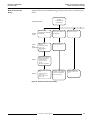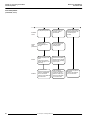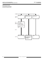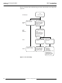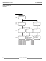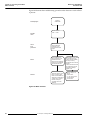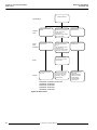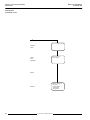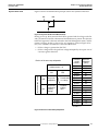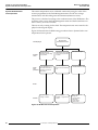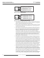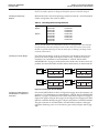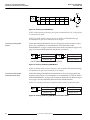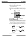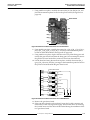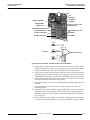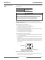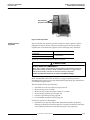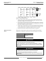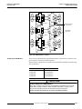
1
Instruction Bulletin VD0C06S701 December 1996 Price $120.00 TM a 66 Adjustable Frequency Drive Controllers for Asynchronous Motors Service and Troubleshooting Manual 1 to 200 hp, 460 V Note: This manual does not cover: • 230V Drives • 250-400 Hp Drives • ATV56 Drives ! DANGER HAZARDOUS VOLTAGE This product contains energy storage devices. Read and understand this bulletin as well as bulletins supplied with your specific equipment before maintaining or servicing the ALTIVAR 66 Drive controller. Installation, adjustment, service and maintenance of these drive controllers must be performed by qualified personnel. • Confirm that drive controller has been correctly selected, installed, and applied before performing any service or maintenance. • Verify that all drive controller overcurrent protective devices, conductors, enclosures, and other circuit elements have been correctly selected for application and that drive controller is properly grounded in accordance with equipment instruction bulletin recommendations and applicable code requirements. • Some measurements must be done with power applied to equipment. Many parts in this drive controller, including printed circuit boards, operate at line voltage. DO NOT TOUCH. Use personal protective equipment and follow precautions and measurement procedures referenced in this bulletin when making any measurements on energized equipment. Use instruments and insulated tools approved for job. • Disconnect all power before servicing drive controller. WAIT ONE MINUTE until DC bus capacitors discharge, then measure DC bus capacity or voltage between the PA and (-) terminals to verify that DC voltage is less than 45 VDC (refer to “PROCEDURE 1: BUS VOLTAGE MEASUREMENT” in Chapter 5). DC bus LED is not accurate indication of absence of DC bus voltage. • DO NOT short across DC bus capacitors or touch unshielded components or terminal strip screw connections with voltage present. • Install all covers and close drive controller door before applying power or starting and stopping drive controller. • Observe and follow all applicable lock-out and tag-out procedures for specific installation. Failure to follow these instructions will cause shock or burn, resulting in death or serious injury. ALTIVAR is a trademark of Telemecanique S.A. or its successor-in-interest, Schneider Electric S.A. Thermalcote is a registered trademark of Thermalloy, Inc. Thermstrate‘ is a trademark of Power Devices, Inc. Torx is a registered trademark of Textron, Inc. © 1996 Square D All Rights Reserved. This document may not be copied in whole or in part, or transferred to any other media without the written permission of Square D. Electrical equipment should be serviced only by qualified electrical maintenance personnel. No responsibility is assumed by Square D for any consequences arising out of the use of this material. Bulletin No. VD0C06S701 December 1996 Chapter 1: Introduction ALTIVAR 66 Service and Troubleshooting Manual Table of Contents ALTIVAR 66 FAMILY . . . . . . . . . . . . . . . . . . . . . . . . . . . . . . . . . . . . . . . . . . . . . . . . . . . . . .2 SCOPE OF MANUAL . . . . . . . . . . . . . . . . . . . . . . . . . . . . . . . . . . . . . . . . . . . . . . . . . . . . . .2 HOW TO USE THIS MANUAL . . . . . . . . . . . . . . . . . . . . . . . . . . . . . . . . . . . . . . . . . . . . . . .2 WORK PRACTICE PRECAUTIONS . . . . . . . . . . . . . . . . . . . . . . . . . . . . . . . . . . . . . . . . . .3 Personnel Protection Precautions . . . . . . . . . . . . . . . . . . . . . . . . . . . . . . . . . . . . . . . .3 Equipment Protection Precautions . . . . . . . . . . . . . . . . . . . . . . . . . . . . . . . . . . . . . . . .4 Static Sensitive Components . . . . . . . . . . . . . . . . . . . . . . . . . . . . . . . . . . . . . . . . . . . .4 LIST OF TOOLS AND INSTRUMENTS . . . . . . . . . . . . . . . . . . . . . . . . . . . . . . . . . . . . . . . .5 DOCUMENTATION LIST . . . . . . . . . . . . . . . . . . . . . . . . . . . . . . . . . . . . . . . . . . . . . . . . . . .5 STANDARDS . . . . . . . . . . . . . . . . . . . . . . . . . . . . . . . . . . . . . . . . . . . . . . . . . . . . . . . . . . . .6 REVISION LEVEL . . . . . . . . . . . . . . . . . . . . . . . . . . . . . . . . . . . . . . . . . . . . . . . . . . . . . . . .6 Chapter 2: Investigating the Problem INTRODUCTION . . . . . . . . . . . . . . . . . . . . . . . . . . . . . . . . . . . . . . . . . . . . . . . . . . . . . . . . .8 RECOMMENDED TROUBLESHOOTING INSTRUCTIONS . . . . . . . . . . . . . . . . . . . . . . . .8 Drive System Energized . . . . . . . . . . . . . . . . . . . . . . . . . . . . . . . . . . . . . . . . . . . . . . . .9 Drive System De-energized (Power Removed) . . . . . . . . . . . . . . . . . . . . . . . . . . . . .11 LED INDICATIONS AND KEYPAD DISPLAY . . . . . . . . . . . . . . . . . . . . . . . . . . . . . . . . . .12 LEDs . . . . . . . . . . . . . . . . . . . . . . . . . . . . . . . . . . . . . . . . . . . . . . . . . . . . . . . . . . . . . .12 Keypad Display . . . . . . . . . . . . . . . . . . . . . . . . . . . . . . . . . . . . . . . . . . . . . . . . . . . . . .13 Status Codes . . . . . . . . . . . . . . . . . . . . . . . . . . . . . . . . . . . . . . . . . . . . . . . . . . . .14 Measurements . . . . . . . . . . . . . . . . . . . . . . . . . . . . . . . . . . . . . . . . . . . . . . . . . . .14 I/O Map. . . . . . . . . . . . . . . . . . . . . . . . . . . . . . . . . . . . . . . . . . . . . . . . . . . . . . . . .15 Fault History . . . . . . . . . . . . . . . . . . . . . . . . . . . . . . . . . . . . . . . . . . . . . . . . . . . . .16 Parameter Settings. . . . . . . . . . . . . . . . . . . . . . . . . . . . . . . . . . . . . . . . . . . . . . . .16 FAULT CATEGORIES . . . . . . . . . . . . . . . . . . . . . . . . . . . . . . . . . . . . . . . . . . . . . . . . . . . .16 Chapter 3: Correcting the Problem RUNS—DOES NOT PERFORM AS EXPECTED . . . . . . . . . . . . . . . . . . . . . . . . . . . . . . .20 Poor Speed Stability . . . . . . . . . . . . . . . . . . . . . . . . . . . . . . . . . . . . . . . . . . . . . . . . . .20 Excessive Motor Temperature . . . . . . . . . . . . . . . . . . . . . . . . . . . . . . . . . . . . . . . . . .22 Motor Accelerates Too Slowly . . . . . . . . . . . . . . . . . . . . . . . . . . . . . . . . . . . . . . . . . .25 Motor Decelerates Too Slowly/Overspeeds/Overspeed Trip . . . . . . . . . . . . . . . . . . .28 Cannot Start Motor . . . . . . . . . . . . . . . . . . . . . . . . . . . . . . . . . . . . . . . . . . . . . . . . . . .32 Cannot Stop Motor . . . . . . . . . . . . . . . . . . . . . . . . . . . . . . . . . . . . . . . . . . . . . . . . . . .37 Motor Turns in Wrong Direction . . . . . . . . . . . . . . . . . . . . . . . . . . . . . . . . . . . . . . . . .40 Drive Will Not Follow Speed Command . . . . . . . . . . . . . . . . . . . . . . . . . . . . . . . . . . .41 Specific Drive Function Does Not Work as Expected/Not at All . . . . . . . . . . . . . . . . .41 TRIPS—RESETTABLE BY KEYPAD/LI/AUTOMATIC/POWER CYCLE . . . . . . . . . . . . . .43 Undervoltage . . . . . . . . . . . . . . . . . . . . . . . . . . . . . . . . . . . . . . . . . . . . . . . . . . . . . . .43 Overvoltage . . . . . . . . . . . . . . . . . . . . . . . . . . . . . . . . . . . . . . . . . . . . . . . . . . . . . . . .45 DC Bus Overvoltage . . . . . . . . . . . . . . . . . . . . . . . . . . . . . . . . . . . . . . . . . . . . . . . . . .47 Input Phase Loss . . . . . . . . . . . . . . . . . . . . . . . . . . . . . . . . . . . . . . . . . . . . . . . . . . . .51 Motor Overload . . . . . . . . . . . . . . . . . . . . . . . . . . . . . . . . . . . . . . . . . . . . . . . . . . . . . .53 Drive Overtemperature . . . . . . . . . . . . . . . . . . . . . . . . . . . . . . . . . . . . . . . . . . . . . . . .55 Loss of Follower . . . . . . . . . . . . . . . . . . . . . . . . . . . . . . . . . . . . . . . . . . . . . . . . . . . . .57 Output Phase Loss . . . . . . . . . . . . . . . . . . . . . . . . . . . . . . . . . . . . . . . . . . . . . . . . . . .58 Sequence Time Out . . . . . . . . . . . . . . . . . . . . . . . . . . . . . . . . . . . . . . . . . . . . . . . . . .60 Process Time Out . . . . . . . . . . . . . . . . . . . . . . . . . . . . . . . . . . . . . . . . . . . . . . . . . . . .60 Serial Link Fault . . . . . . . . . . . . . . . . . . . . . . . . . . . . . . . . . . . . . . . . . . . . . . . . . . . . .60 © 1996 Square D All Rights Reserved i ALTIVAR 66 Service and Troubleshooting Manual Table of Contents Bulletin No. VD0C06S701 December 1996 TRIPS—REQUIRES POWER TO BE CYCLED . . . . . . . . . . . . . . . . . . . . . . . . . . . . . . . . 61 Short Circuit . . . . . . . . . . . . . . . . . . . . . . . . . . . . . . . . . . . . . . . . . . . . . . . . . . . . . . . . 61 Ground Fault . . . . . . . . . . . . . . . . . . . . . . . . . . . . . . . . . . . . . . . . . . . . . . . . . . . . . . . 63 Internal Fault . . . . . . . . . . . . . . . . . . . . . . . . . . . . . . . . . . . . . . . . . . . . . . . . . . . . . . . 65 Internal Fault (continued, 2 of 2) . . . . . . . . . . . . . . . . . . . . . . . . . . . . . . . . . . . . . . . . 66 Dynamic Brake Fault . . . . . . . . . . . . . . . . . . . . . . . . . . . . . . . . . . . . . . . . . . . . . . . . . 67 Dynamic Brake Resistor Overtemperature . . . . . . . . . . . . . . . . . . . . . . . . . . . . . . . . 68 Memory Failure . . . . . . . . . . . . . . . . . . . . . . . . . . . . . . . . . . . . . . . . . . . . . . . . . . . . . 69 Precharge Failure . . . . . . . . . . . . . . . . . . . . . . . . . . . . . . . . . . . . . . . . . . . . . . . . . . . 69 Link Fault . . . . . . . . . . . . . . . . . . . . . . . . . . . . . . . . . . . . . . . . . . . . . . . . . . . . . . . . . . 69 Control Supply Fault . . . . . . . . . . . . . . . . . . . . . . . . . . . . . . . . . . . . . . . . . . . . . . . . . 69 EQUIPMENT DAMAGE . . . . . . . . . . . . . . . . . . . . . . . . . . . . . . . . . . . . . . . . . . . . . . . . . . . 70 KEYPAD DISPLAY IS OFF . . . . . . . . . . . . . . . . . . . . . . . . . . . . . . . . . . . . . . . . . . . . . . . . 70 External Signs of Equipment Damage . . . . . . . . . . . . . . . . . . . . . . . . . . . . . . . . . . . . 70 No External Signs of Equipment Damage . . . . . . . . . . . . . . . . . . . . . . . . . . . . . . . . . 70 Checking the Power Part of the Drive Controller . . . . . . . . . . . . . . . . . . . . . . . . . . . . 71 Checking Fuses in ATV66C10N4 to C19N4 controllers . . . . . . . . . . . . . . . . . . . 72 Checking the Diode Bridge . . . . . . . . . . . . . . . . . . . . . . . . . . . . . . . . . . . . . . . . . 73 Checking the DC Bus . . . . . . . . . . . . . . . . . . . . . . . . . . . . . . . . . . . . . . . . . . . . . 73 Checking the Precharge Resistor . . . . . . . . . . . . . . . . . . . . . . . . . . . . . . . . . . . . 75 Checking the Inverter Bridge . . . . . . . . . . . . . . . . . . . . . . . . . . . . . . . . . . . . . . . . 75 Checking the IGBT Modules in ATV66D16N4 to C19N4 Drive Controllers. . . . . 75 Checking the Braking IGBT Module . . . . . . . . . . . . . . . . . . . . . . . . . . . . . . . . . . 76 Checking the Braking IGBT Module Freewheel Diode . . . . . . . . . . . . . . . . . . . . 76 Checkout of the Control Part of the Drive Controller . . . . . . . . . . . . . . . . . . . . . . . . . 77 Drive Controller Internal Measurements Check. . . . . . . . . . . . . . . . . . . . . . . . . . 78 Checking Fault History . . . . . . . . . . . . . . . . . . . . . . . . . . . . . . . . . . . . . . . . . . . . . . . . 79 Checking the 24 VDC and 10 VDC User Power Supplies. . . . . . . . . . . . . . . . . . 79 Checking the Keypad Display . . . . . . . . . . . . . . . . . . . . . . . . . . . . . . . . . . . . . . . 80 Diagnostic Mode . . . . . . . . . . . . . . . . . . . . . . . . . . . . . . . . . . . . . . . . . . . . . . . . . 81 Autodiagnostics . . . . . . . . . . . . . . . . . . . . . . . . . . . . . . . . . . . . . . . . . . . . . . . . . . 81 Logic and Analog Input/Output Tests . . . . . . . . . . . . . . . . . . . . . . . . . . . . . . . . . 81 Chapter 4: Equipment Change Out Procedures GENERAL . . . . . . . . . . . . . . . . . . . . . . . . . . . . . . . . . . . . . . . . . . . . . . . . . . . . . . . . . . . . . 86 ATV66U41N4 TO U72N4. . . . . . . . . . . . . . . . . . . . . . . . . . . . . . . . . . . . . . . . . . . . . . . . . . 86 Replacing the Keypad Display . . . . . . . . . . . . . . . . . . . . . . . . . . . . . . . . . . . . . . . . . . 87 Removing the Control Basket . . . . . . . . . . . . . . . . . . . . . . . . . . . . . . . . . . . . . . . . . . 88 Installing the Control Basket . . . . . . . . . . . . . . . . . . . . . . . . . . . . . . . . . . . . . . . . . . . 90 Replacing Control Terminal Blocks . . . . . . . . . . . . . . . . . . . . . . . . . . . . . . . . . . . . . . 91 Replacing the Power Board . . . . . . . . . . . . . . . . . . . . . . . . . . . . . . . . . . . . . . . . . . . . 92 Removing the Fan . . . . . . . . . . . . . . . . . . . . . . . . . . . . . . . . . . . . . . . . . . . . . . . . . . . 94 Installing the Fan . . . . . . . . . . . . . . . . . . . . . . . . . . . . . . . . . . . . . . . . . . . . . . . . . . . . 96 ATV66U90N4 AND D12N4 . . . . . . . . . . . . . . . . . . . . . . . . . . . . . . . . . . . . . . . . . . . . . . . . 99 Replacing the Keypad Display . . . . . . . . . . . . . . . . . . . . . . . . . . . . . . . . . . . . . . . . . 100 Removing the Control Basket . . . . . . . . . . . . . . . . . . . . . . . . . . . . . . . . . . . . . . . . . 101 Installing the Control Basket . . . . . . . . . . . . . . . . . . . . . . . . . . . . . . . . . . . . . . . . . . 103 Replacing Control Terminal Blocks . . . . . . . . . . . . . . . . . . . . . . . . . . . . . . . . . . . . . 104 Replacing the Power Board . . . . . . . . . . . . . . . . . . . . . . . . . . . . . . . . . . . . . . . . . . . 106 Removing the Fan . . . . . . . . . . . . . . . . . . . . . . . . . . . . . . . . . . . . . . . . . . . . . . . . . . 108 Installing the Fan . . . . . . . . . . . . . . . . . . . . . . . . . . . . . . . . . . . . . . . . . . . . . . . . . . . 109 ii © 1996 Square D All Rights Reserved Bulletin No. VD0C06S701 December1996 ALTIVAR 66 Service and Troubleshooting Manual Table of Contents ATV66D16N4 AND D23N4. . . . . . . . . . . . . . . . . . . . . . . . . . . . . . . . . . . . . . . . . . . . . . . .111 Replacing the Keypad Display . . . . . . . . . . . . . . . . . . . . . . . . . . . . . . . . . . . . . . . . .112 Removing the Control Basket . . . . . . . . . . . . . . . . . . . . . . . . . . . . . . . . . . . . . . . . . .113 Installing the Control Basket . . . . . . . . . . . . . . . . . . . . . . . . . . . . . . . . . . . . . . . . . . .115 Replacing Control Terminal Blocks . . . . . . . . . . . . . . . . . . . . . . . . . . . . . . . . . . . . .116 Removing the Gate Driver Board . . . . . . . . . . . . . . . . . . . . . . . . . . . . . . . . . . . . . . .117 Installing the Gate Driver Board . . . . . . . . . . . . . . . . . . . . . . . . . . . . . . . . . . . . . . . .120 Removing the Power Board . . . . . . . . . . . . . . . . . . . . . . . . . . . . . . . . . . . . . . . . . . .121 Installing the Power Board . . . . . . . . . . . . . . . . . . . . . . . . . . . . . . . . . . . . . . . . . . . .124 Removing the IGBT Module . . . . . . . . . . . . . . . . . . . . . . . . . . . . . . . . . . . . . . . . . . .126 Installing the IGBT Module . . . . . . . . . . . . . . . . . . . . . . . . . . . . . . . . . . . . . . . . . . . .128 Removing the Braking IGBT Module . . . . . . . . . . . . . . . . . . . . . . . . . . . . . . . . . . . .129 Installing the Braking IGBT Module . . . . . . . . . . . . . . . . . . . . . . . . . . . . . . . . . . . . .131 Removing the Filter Board . . . . . . . . . . . . . . . . . . . . . . . . . . . . . . . . . . . . . . . . . . . .132 Installing the Filter Board . . . . . . . . . . . . . . . . . . . . . . . . . . . . . . . . . . . . . . . . . . . . .134 Removing the Diode Bridge . . . . . . . . . . . . . . . . . . . . . . . . . . . . . . . . . . . . . . . . . . .135 Installing the Diode Bridge . . . . . . . . . . . . . . . . . . . . . . . . . . . . . . . . . . . . . . . . . . . .136 Replacing the Precharge Resistor . . . . . . . . . . . . . . . . . . . . . . . . . . . . . . . . . . . . . .137 Removing the Fan . . . . . . . . . . . . . . . . . . . . . . . . . . . . . . . . . . . . . . . . . . . . . . . . . .138 Installing the Fan . . . . . . . . . . . . . . . . . . . . . . . . . . . . . . . . . . . . . . . . . . . . . . . . . . .140 Removing the Bus Capacitors . . . . . . . . . . . . . . . . . . . . . . . . . . . . . . . . . . . . . . . . .141 Installing the Bus Capacitors . . . . . . . . . . . . . . . . . . . . . . . . . . . . . . . . . . . . . . . . . .143 ATV66D33N4 AND D46N4. . . . . . . . . . . . . . . . . . . . . . . . . . . . . . . . . . . . . . . . . . . . . . . .145 Replacing the Keypad Display . . . . . . . . . . . . . . . . . . . . . . . . . . . . . . . . . . . . . . . . .146 Removing the Control Basket . . . . . . . . . . . . . . . . . . . . . . . . . . . . . . . . . . . . . . . . . .147 Installing the Control Basket . . . . . . . . . . . . . . . . . . . . . . . . . . . . . . . . . . . . . . . . . . .149 Replacing Control Terminal Blocks . . . . . . . . . . . . . . . . . . . . . . . . . . . . . . . . . . . . .150 Replacing the Board Fan . . . . . . . . . . . . . . . . . . . . . . . . . . . . . . . . . . . . . . . . . . . . .152 Removing the Gate Driver Board . . . . . . . . . . . . . . . . . . . . . . . . . . . . . . . . . . . . . . .154 Installing the Gate Driver Board . . . . . . . . . . . . . . . . . . . . . . . . . . . . . . . . . . . . . . . .156 Removing the Power Board . . . . . . . . . . . . . . . . . . . . . . . . . . . . . . . . . . . . . . . . . . .157 Installing the Power Board . . . . . . . . . . . . . . . . . . . . . . . . . . . . . . . . . . . . . . . . . . . .159 Removing the IGBT Module . . . . . . . . . . . . . . . . . . . . . . . . . . . . . . . . . . . . . . . . . . .161 Installing the IGBT Module . . . . . . . . . . . . . . . . . . . . . . . . . . . . . . . . . . . . . . . . . . . .163 Removing the Braking IGBT Module . . . . . . . . . . . . . . . . . . . . . . . . . . . . . . . . . . . .165 Installing the Braking IGBT Module . . . . . . . . . . . . . . . . . . . . . . . . . . . . . . . . . . . . .166 Removing the Bus Capacitors . . . . . . . . . . . . . . . . . . . . . . . . . . . . . . . . . . . . . . . . .167 Installing the Bus Capacitors . . . . . . . . . . . . . . . . . . . . . . . . . . . . . . . . . . . . . . . . . .169 Removing the Filter Board . . . . . . . . . . . . . . . . . . . . . . . . . . . . . . . . . . . . . . . . . . . .171 Installing the Filter Board . . . . . . . . . . . . . . . . . . . . . . . . . . . . . . . . . . . . . . . . . . . . .173 Removing the Diode Block . . . . . . . . . . . . . . . . . . . . . . . . . . . . . . . . . . . . . . . . . . . .175 Installing the Diode Block . . . . . . . . . . . . . . . . . . . . . . . . . . . . . . . . . . . . . . . . . . . . .177 Replacing the Current Sensor . . . . . . . . . . . . . . . . . . . . . . . . . . . . . . . . . . . . . . . . .178 Removing the Fan . . . . . . . . . . . . . . . . . . . . . . . . . . . . . . . . . . . . . . . . . . . . . . . . . .181 Installing the Fan . . . . . . . . . . . . . . . . . . . . . . . . . . . . . . . . . . . . . . . . . . . . . . . . . . .182 Replacing the Discharge Resistor . . . . . . . . . . . . . . . . . . . . . . . . . . . . . . . . . . . . . .183 Replacing the Auto Transformer . . . . . . . . . . . . . . . . . . . . . . . . . . . . . . . . . . . . . . . .185 ATV66D54N4 TO D79N4 . . . . . . . . . . . . . . . . . . . . . . . . . . . . . . . . . . . . . . . . . . . . . . . . .189 Replacing the Keypad Display . . . . . . . . . . . . . . . . . . . . . . . . . . . . . . . . . . . . . . . . .190 Removing the Control Basket . . . . . . . . . . . . . . . . . . . . . . . . . . . . . . . . . . . . . . . . . .191 © 1996 Square D All Rights Reserved iii ALTIVAR 66 Service and Troubleshooting Manual Table of Contents Bulletin No. VD0C06S701 December1996 Installing the Control Basket . . . . . . . . . . . . . . . . . . . . . . . . . . . . . . . . . . . . . . . . . . 193 Replacing Control Terminal Blocks . . . . . . . . . . . . . . . . . . . . . . . . . . . . . . . . . . . . . 194 Replacing the Board Fan . . . . . . . . . . . . . . . . . . . . . . . . . . . . . . . . . . . . . . . . . . . . . 196 Removing the Gate Driver Board . . . . . . . . . . . . . . . . . . . . . . . . . . . . . . . . . . . . . . . 198 Installing the Gate Driver Board . . . . . . . . . . . . . . . . . . . . . . . . . . . . . . . . . . . . . . . . 200 Removing the Power Board . . . . . . . . . . . . . . . . . . . . . . . . . . . . . . . . . . . . . . . . . . . 201 Installing the Power Board . . . . . . . . . . . . . . . . . . . . . . . . . . . . . . . . . . . . . . . . . . . . 203 Removing the IGBT Module . . . . . . . . . . . . . . . . . . . . . . . . . . . . . . . . . . . . . . . . . . 205 Installing the IGBT Module . . . . . . . . . . . . . . . . . . . . . . . . . . . . . . . . . . . . . . . . . . . 207 Removing the Braking IGBT Module . . . . . . . . . . . . . . . . . . . . . . . . . . . . . . . . . . . . 208 Installing the Braking IGBT Module . . . . . . . . . . . . . . . . . . . . . . . . . . . . . . . . . . . . . 210 Removing the Bus Capacitor Assembly . . . . . . . . . . . . . . . . . . . . . . . . . . . . . . . . . 211 Installing the Bus Capacitor Assembly . . . . . . . . . . . . . . . . . . . . . . . . . . . . . . . . . . 213 Removing the Filter Board . . . . . . . . . . . . . . . . . . . . . . . . . . . . . . . . . . . . . . . . . . . . 215 Installing the Filter Board . . . . . . . . . . . . . . . . . . . . . . . . . . . . . . . . . . . . . . . . . . . . . 217 Removing the Diode Block . . . . . . . . . . . . . . . . . . . . . . . . . . . . . . . . . . . . . . . . . . . 219 Installing the Diode Block . . . . . . . . . . . . . . . . . . . . . . . . . . . . . . . . . . . . . . . . . . . . 220 Replacing the Current Sensor . . . . . . . . . . . . . . . . . . . . . . . . . . . . . . . . . . . . . . . . . 221 Removing the Main Fan . . . . . . . . . . . . . . . . . . . . . . . . . . . . . . . . . . . . . . . . . . . . . . 223 Installing the Main Fan . . . . . . . . . . . . . . . . . . . . . . . . . . . . . . . . . . . . . . . . . . . . . . . 225 Replacing the Precharge Resistor . . . . . . . . . . . . . . . . . . . . . . . . . . . . . . . . . . . . . . 226 Replacing the Discharge Resistor . . . . . . . . . . . . . . . . . . . . . . . . . . . . . . . . . . . . . . 227 Replacing the Auto Transformer . . . . . . . . . . . . . . . . . . . . . . . . . . . . . . . . . . . . . . . 230 ATV66C10N4 TO C19N4. . . . . . . . . . . . . . . . . . . . . . . . . . . . . . . . . . . . . . . . . . . . . . . . . 233 Replacing the Keypad Display . . . . . . . . . . . . . . . . . . . . . . . . . . . . . . . . . . . . . . . . . 236 Removing the Control Basket . . . . . . . . . . . . . . . . . . . . . . . . . . . . . . . . . . . . . . . . . 237 Installing the Control Basket . . . . . . . . . . . . . . . . . . . . . . . . . . . . . . . . . . . . . . . . . . 240 Replacing Control Terminal Blocks . . . . . . . . . . . . . . . . . . . . . . . . . . . . . . . . . . . . . 241 Removing the Power Board . . . . . . . . . . . . . . . . . . . . . . . . . . . . . . . . . . . . . . . . . . . 243 Installing the Power Board . . . . . . . . . . . . . . . . . . . . . . . . . . . . . . . . . . . . . . . . . . . . 246 Removing the Snubber Board . . . . . . . . . . . . . . . . . . . . . . . . . . . . . . . . . . . . . . . . . 247 Installing the Snubber Board . . . . . . . . . . . . . . . . . . . . . . . . . . . . . . . . . . . . . . . . . . 249 Removing the Gate Driver Board . . . . . . . . . . . . . . . . . . . . . . . . . . . . . . . . . . . . . . . 250 Installing the Gate Driver Board . . . . . . . . . . . . . . . . . . . . . . . . . . . . . . . . . . . . . . . . 252 Removing the IGBT Module . . . . . . . . . . . . . . . . . . . . . . . . . . . . . . . . . . . . . . . . . . 253 Installing the IGBT Module . . . . . . . . . . . . . . . . . . . . . . . . . . . . . . . . . . . . . . . . . . . 255 Removing the Diode Block . . . . . . . . . . . . . . . . . . . . . . . . . . . . . . . . . . . . . . . . . . . 257 Installing the Diode Block . . . . . . . . . . . . . . . . . . . . . . . . . . . . . . . . . . . . . . . . . . . . 259 Removing the Current Sensor Assembly . . . . . . . . . . . . . . . . . . . . . . . . . . . . . . . . . 261 Installing the Current Sensor Assembly . . . . . . . . . . . . . . . . . . . . . . . . . . . . . . . . . . 263 Removing the Dynamic Braking (DB) Snubber Board . . . . . . . . . . . . . . . . . . . . . . . 264 Installing the Dynamic Braking (DB) Snubber Board . . . . . . . . . . . . . . . . . . . . . . . . 267 Removing the Dynamic Braking (DB) Gate Driver Board . . . . . . . . . . . . . . . . . . . . 268 Installing the Dynamic Braking (DB) Gate Driver Board . . . . . . . . . . . . . . . . . . . . . 269 Removing the Dynamic Braking (DB) IGBT Module . . . . . . . . . . . . . . . . . . . . . . . . 271 Installing the Dynamic Braking (DB) IGBT Module . . . . . . . . . . . . . . . . . . . . . . . . . 272 Removing the Dynamic Braking (DB) Diode Block . . . . . . . . . . . . . . . . . . . . . . . . . 273 Installing the Dynamic Braking (DB) Diode Block . . . . . . . . . . . . . . . . . . . . . . . . . . 276 Replacing the Thermal Switches . . . . . . . . . . . . . . . . . . . . . . . . . . . . . . . . . . . . . . . 277 Replacing the Filter Board Assembly . . . . . . . . . . . . . . . . . . . . . . . . . . . . . . . . . . . . 280 Replacing the Capacitor Assembly . . . . . . . . . . . . . . . . . . . . . . . . . . . . . . . . . . . . . 282 iv © 1996 Square D All Rights Reserved Bulletin No. VD0C06S701 December 1996 ALTIVAR 66 Service and Troubleshooting Manual Table of Contents Removing the Control Power Transformer . . . . . . . . . . . . . . . . . . . . . . . . . . . . . . . .287 Installing the Control Power Transformer . . . . . . . . . . . . . . . . . . . . . . . . . . . . . . . . .289 Replacing the Stirring Fan . . . . . . . . . . . . . . . . . . . . . . . . . . . . . . . . . . . . . . . . . . . .291 Removing the Main Fan . . . . . . . . . . . . . . . . . . . . . . . . . . . . . . . . . . . . . . . . . . . . . .292 Installing the Main Fan . . . . . . . . . . . . . . . . . . . . . . . . . . . . . . . . . . . . . . . . . . . . . . .294 Replacing the Discharge Resistor . . . . . . . . . . . . . . . . . . . . . . . . . . . . . . . . . . . . . .295 Replacing the Precharge Resistor . . . . . . . . . . . . . . . . . . . . . . . . . . . . . . . . . . . . . .296 Replacing the Contactor Auxiliary Contact Block . . . . . . . . . . . . . . . . . . . . . . . . . . .298 Removing the Precharge Contactor . . . . . . . . . . . . . . . . . . . . . . . . . . . . . . . . . . . . .301 Installing the Precharge Contactor . . . . . . . . . . . . . . . . . . . . . . . . . . . . . . . . . . . . . .302 Replacing the Circuit Protector . . . . . . . . . . . . . . . . . . . . . . . . . . . . . . . . . . . . . . . . .305 Replacing the Control Fuses . . . . . . . . . . . . . . . . . . . . . . . . . . . . . . . . . . . . . . . . . .306 Replacing the DC Bus Fuse . . . . . . . . . . . . . . . . . . . . . . . . . . . . . . . . . . . . . . . . . . .306 Chapter 5: Basic Procedures PRECAUTIONS . . . . . . . . . . . . . . . . . . . . . . . . . . . . . . . . . . . . . . . . . . . . . . . . . . . . . . . .310 PROCEDURE 1: BUS VOLTAGE MEASUREMENT . . . . . . . . . . . . . . . . . . . . . . . . . . . .310 PROCEDURE 2: DISCHARGING STORED ENERGY IN CAPACITORS . . . . . . . . . . . .311 PROCEDURE 3: INPUT LINE VOLTAGE MEASUREMENT . . . . . . . . . . . . . . . . . . . . . .313 PROCEDURE 4: CHECKING PERIPHERAL EQUIPMENT. . . . . . . . . . . . . . . . . . . . . . .313 PROCEDURE 5: VALIDATION AFTER REPAIR . . . . . . . . . . . . . . . . . . . . . . . . . . . . . . .314 PROCEDURE 6: CHECKING FAN OPERATION . . . . . . . . . . . . . . . . . . . . . . . . . . . . . .315 PROCEDURE 7: CLEANING HEAT SINKSAND AIR PASSAGES . . . . . . . . . . . . . . . . .316 PROCEDURE 8: RUNNING DRIVE CONTROLLER FROM CONTROL POWER ONLY 316 PROCEDURE 9: CHECKING THE SOFTWARE REVISION LEVEL. . . . . . . . . . . . . . . .317 Appendix TO ORDER REPLACEMENT PARTS . . . . . . . . . . . . . . . . . . . . . . . . . . . . . . . . . . . . . . .319 LOCAL SUPPORT . . . . . . . . . . . . . . . . . . . . . . . . . . . . . . . . . . . . . . . . . . . . . . . . . . . . . .319 FACTORY TELEPHONE SUPPORT . . . . . . . . . . . . . . . . . . . . . . . . . . . . . . . . . . . . . . . .319 FACTORY REPAIR . . . . . . . . . . . . . . . . . . . . . . . . . . . . . . . . . . . . . . . . . . . . . . . . . . . . .319 ON-SITE REPAIR. . . . . . . . . . . . . . . . . . . . . . . . . . . . . . . . . . . . . . . . . . . . . . . . . . . . . . .319 © 1996 Square D All Rights Reserved v ALTIVAR 66 Service and Troubleshooting Manual Table of Contents vi Bulletin No. VD0C06S701 December 1996 © 1996 Square D All Rights Reserved Bulletin No. VD0C06S701 December 1996 ALTIVAR 66 Service and Troubleshooting Manual List of Figures & Tables LIST OF FIGURES Figure 1: Figure 2: Figure 3: Figure 4: Figure 5: Figure 6: Figure 7: Figure 8: Figure 9: Figure 10: Figure 11: Figure 12: Figure 13: Figure 14: Figure 15: Figure 16: Figure 17: Figure 18: Figure 19: Figure 20: Figure 21: Figure 22: Figure 23: Figure 24: Figure 25: Figure 26: Figure 27: Figure 28: Figure 29: Figure 30: Figure 31: Figure 32: Figure 33: Figure 34: Figure 35: Figure 36: Figure 37: Figure 38: Figure 39: Figure 40: Figure 41: Figure 42: Figure 43: Figure 44: Figure 45: Figure 46: Figure 47: Figure 48: Figure 49: Typical Causes and Severity of Faults . . . . . . . . . . . . . . . . . . . . . . . . . .8 LED Indications . . . . . . . . . . . . . . . . . . . . . . . . . . . . . . . . . . . . . . . . . . .13 Display Screen Status Code Location . . . . . . . . . . . . . . . . . . . . . . . . . .14 I/O Map . . . . . . . . . . . . . . . . . . . . . . . . . . . . . . . . . . . . . . . . . . . . . . . . .15 Fault History. . . . . . . . . . . . . . . . . . . . . . . . . . . . . . . . . . . . . . . . . . . . . .16 Poor Speed Stability . . . . . . . . . . . . . . . . . . . . . . . . . . . . . . . . . . . . . . .20 Excessive Motor Temperature . . . . . . . . . . . . . . . . . . . . . . . . . . . . . . . .22 Motor Accelerates Too Slowly . . . . . . . . . . . . . . . . . . . . . . . . . . . . . . . .25 Motor Decelerates Slowly/Not at All/Overspeeds/Overspeed Trip . . . .28 Cannot Start Motor . . . . . . . . . . . . . . . . . . . . . . . . . . . . . . . . . . . . . . . .32 Cannot Stop Motor. . . . . . . . . . . . . . . . . . . . . . . . . . . . . . . . . . . . . . . . .37 Motor Turns in Wrong Direction . . . . . . . . . . . . . . . . . . . . . . . . . . . . . . .40 Specific Drive Function Does Not Work as Expected/Not at All . . . . . .41 Undervoltage Measurement . . . . . . . . . . . . . . . . . . . . . . . . . . . . . . . . .43 Undervoltage . . . . . . . . . . . . . . . . . . . . . . . . . . . . . . . . . . . . . . . . . . . . .44 Line Overvoltage Measurement. . . . . . . . . . . . . . . . . . . . . . . . . . . . . . .45 Line Overvoltage . . . . . . . . . . . . . . . . . . . . . . . . . . . . . . . . . . . . . . . . . .46 DC Bus Overvoltage Measurement . . . . . . . . . . . . . . . . . . . . . . . . . . . .47 DC Bus Overvoltage . . . . . . . . . . . . . . . . . . . . . . . . . . . . . . . . . . . . . . .48 Input Phase Loss Measurement . . . . . . . . . . . . . . . . . . . . . . . . . . . . . .51 Input Phase Loss . . . . . . . . . . . . . . . . . . . . . . . . . . . . . . . . . . . . . . . . . .52 Motor Overload . . . . . . . . . . . . . . . . . . . . . . . . . . . . . . . . . . . . . . . . . . .54 Drive Overtemperature Measurement . . . . . . . . . . . . . . . . . . . . . . . . . .55 Drive Overtemperature . . . . . . . . . . . . . . . . . . . . . . . . . . . . . . . . . . . . .56 Loss Follower. . . . . . . . . . . . . . . . . . . . . . . . . . . . . . . . . . . . . . . . . . . . .57 Output Phase Loss Measurement . . . . . . . . . . . . . . . . . . . . . . . . . . . . .58 Output Phase Loss . . . . . . . . . . . . . . . . . . . . . . . . . . . . . . . . . . . . . . . .59 Short Circuit Measurement . . . . . . . . . . . . . . . . . . . . . . . . . . . . . . . . . .61 Short Circuit . . . . . . . . . . . . . . . . . . . . . . . . . . . . . . . . . . . . . . . . . . . . . .62 Ground Fault Measurement . . . . . . . . . . . . . . . . . . . . . . . . . . . . . . . . . .63 Ground Fault (ATV66D16N4 through ATV66C19N4) . . . . . . . . . . . . . .64 Internal Fault . . . . . . . . . . . . . . . . . . . . . . . . . . . . . . . . . . . . . . . . . . . . .65 Dynamic Brake Fault Measurement . . . . . . . . . . . . . . . . . . . . . . . . . . .67 Review of Auto Ramp Adaptation . . . . . . . . . . . . . . . . . . . . . . . . . . . . .67 DB Resistor Overtemperature . . . . . . . . . . . . . . . . . . . . . . . . . . . . . . . .68 Power Part Electrical Schematic . . . . . . . . . . . . . . . . . . . . . . . . . . . . . .71 F4 Bus Fuse Test Procedure: ATV66C10N4 to C19N4 . . . . . . . . . . . .72 Checking the Diode Bridge . . . . . . . . . . . . . . . . . . . . . . . . . . . . . . . . . .73 Checking the Rectifier Bus . . . . . . . . . . . . . . . . . . . . . . . . . . . . . . . . . .74 Checking the Capacitor and Inverter Bus . . . . . . . . . . . . . . . . . . . . . . .74 Checking the Inverter Bridge . . . . . . . . . . . . . . . . . . . . . . . . . . . . . . . . .75 Checking the IGBT Modules . . . . . . . . . . . . . . . . . . . . . . . . . . . . . . . . .76 Checking the Braking IGBT Module . . . . . . . . . . . . . . . . . . . . . . . . . . .76 Checking the Braking IGBT Module Freewheel Diode . . . . . . . . . . . . .76 Drive Controller Power Part Measurements . . . . . . . . . . . . . . . . . . . . .78 ATV66U41N4 to U72N4 Front View . . . . . . . . . . . . . . . . . . . . . . . . . . .87 Control Basket Connector Locations . . . . . . . . . . . . . . . . . . . . . . . . . . .89 Cable Connector Secure and Release Positions. . . . . . . . . . . . . . . . . .89 Location of J1, J2, J12, and J13 Connectors. . . . . . . . . . . . . . . . . . . . .92 © 1996 Square D All Rights Reserved vii ALTIVAR 66 Service and Troubleshooting Manual List of Figures & Tables Bulletin No. VD0C06S701 December 1996 Figure 50: Figure 51: Figure 52: Figure 53: Figure 54: Figure 55: Figure 56: Figure 57: Figure 58: Figure 59: Figure 60: Figure 61: Figure 62: Figure 63: Figure 64: Figure 65: Figure 66: Figure 67: Figure 68: Figure 69: Figure 70: Figure 71: Figure 72: Figure 73: Figure 74: Figure 75: Figure 76: Figure 77: Figure 78: Figure 79: Figure 80: Figure 81: Figure 82: Figure 83: Figure 84: Figure 85: Figure 86: Figure 87: Figure 88: Figure 89: Figure 90: Figure 91: Figure 92: Figure 93: Figure 94: Figure 95: Figure 96: Figure 97: Figure 98: Figure 99: Figure 100: viii Power Board Connector Locations . . . . . . . . . . . . . . . . . . . . . . . . . . . . 94 Fan Removal. . . . . . . . . . . . . . . . . . . . . . . . . . . . . . . . . . . . . . . . . . . . . 96 Fan Lead Routing . . . . . . . . . . . . . . . . . . . . . . . . . . . . . . . . . . . . . . . . . 97 ATV66U90N4 and D12N4 Front View . . . . . . . . . . . . . . . . . . . . . . . . 100 Control Basket Connector Locations . . . . . . . . . . . . . . . . . . . . . . . . . 102 Cable Connector Secure and Release Positions . . . . . . . . . . . . . . . . 102 Location of J1, J2, J12, and J13 Connectors . . . . . . . . . . . . . . . . . . . 105 Power Board Connector Locations . . . . . . . . . . . . . . . . . . . . . . . . . . . 107 Fan Removal. . . . . . . . . . . . . . . . . . . . . . . . . . . . . . . . . . . . . . . . . . . . 109 Fan Lead Routing . . . . . . . . . . . . . . . . . . . . . . . . . . . . . . . . . . . . . . . . 110 ATV66D16N4 to D23N4 Front View . . . . . . . . . . . . . . . . . . . . . . . . . . 112 Control Basket Connector Locations . . . . . . . . . . . . . . . . . . . . . . . . . 114 Cable Connector Secure and Release Positions . . . . . . . . . . . . . . . . 114 Location of J1, J2, J12, and J13 Connectors . . . . . . . . . . . . . . . . . . . 117 Location of Various Covers . . . . . . . . . . . . . . . . . . . . . . . . . . . . . . . . . 118 Gate Driver Board Connections on Power Board . . . . . . . . . . . . . . . . 119 Gate Driver Board Connections on IGBT Modules . . . . . . . . . . . . . . . 119 Connector, Wire, and Nut Locations on Power Board . . . . . . . . . . . . 123 Bus Bar Isolating Screen . . . . . . . . . . . . . . . . . . . . . . . . . . . . . . . . . . 124 Bus Bar Screw and Mounting Pin Locations . . . . . . . . . . . . . . . . . . . . 127 IGBT Modules (Bus Bar Removed). . . . . . . . . . . . . . . . . . . . . . . . . . . 127 Bus Bar Cable Locations . . . . . . . . . . . . . . . . . . . . . . . . . . . . . . . . . . 129 Braking IGBT Module Location . . . . . . . . . . . . . . . . . . . . . . . . . . . . . . 130 Braking IGBT Module Installation Orientation . . . . . . . . . . . . . . . . . . . 131 Filter Board Connections. . . . . . . . . . . . . . . . . . . . . . . . . . . . . . . . . . . 133 Precharge Resistor . . . . . . . . . . . . . . . . . . . . . . . . . . . . . . . . . . . . . . . 138 Fan Mounting . . . . . . . . . . . . . . . . . . . . . . . . . . . . . . . . . . . . . . . . . . . 140 Bus Capacitors . . . . . . . . . . . . . . . . . . . . . . . . . . . . . . . . . . . . . . . . . . 143 Bus Capacitor PA and (-) Terminals . . . . . . . . . . . . . . . . . . . . . . . . . . 144 ATV66D33N4 to D46N4 Front View . . . . . . . . . . . . . . . . . . . . . . . . . . 146 Control Basket Connector Locations . . . . . . . . . . . . . . . . . . . . . . . . . 148 Cable Connector Secure and Release Positions . . . . . . . . . . . . . . . . 149 Location of J1, J2, J12, and J13 Connectors . . . . . . . . . . . . . . . . . . . 151 Location of Various Covers . . . . . . . . . . . . . . . . . . . . . . . . . . . . . . . . . 153 Board Fan-Top Left Side of Drive Controller. . . . . . . . . . . . . . . . . . . . 153 Gate Driver Board Connection Locations . . . . . . . . . . . . . . . . . . . . . . 155 Gate Driver Board Connections on IGBT Modules . . . . . . . . . . . . . . . 155 Power Board Connections . . . . . . . . . . . . . . . . . . . . . . . . . . . . . . . . . 158 Bus Bar Isolating Screen . . . . . . . . . . . . . . . . . . . . . . . . . . . . . . . . . . 160 Bus Bar Screws. . . . . . . . . . . . . . . . . . . . . . . . . . . . . . . . . . . . . . . . . . 162 Drive Controller with Bus Bar Removed . . . . . . . . . . . . . . . . . . . . . . . 163 Bus Capacitors . . . . . . . . . . . . . . . . . . . . . . . . . . . . . . . . . . . . . . . . . . 169 Filter Board (shown with Terminal Block Removed) . . . . . . . . . . . . . . 173 J2 Terminal Block Torque Specs . . . . . . . . . . . . . . . . . . . . . . . . . . . . 174 Diode Block - Bottom left side view of controller . . . . . . . . . . . . . . . . . 176 Diode Block Wiring Terminations . . . . . . . . . . . . . . . . . . . . . . . . . . . . 178 Current Sensor . . . . . . . . . . . . . . . . . . . . . . . . . . . . . . . . . . . . . . . . . . 180 Fan Location and Mounting - Bottom View of Controller . . . . . . . . . . 182 Discharge Resistor . . . . . . . . . . . . . . . . . . . . . . . . . . . . . . . . . . . . . . . 184 Auto Transformer . . . . . . . . . . . . . . . . . . . . . . . . . . . . . . . . . . . . . . . . 186 ATV66D54N4 to D79N4 Front View . . . . . . . . . . . . . . . . . . . . . . . . . . 190 © 1996 Square D All Rights Reserved Bulletin No. VD0C06S701 December 1996 ALTIVAR 66 Service and Troubleshooting Manual List of Figures & Tables Figure 101: Figure 102: Figure 103: Figure 104: Figure 105: Figure 106: Figure 107: Figure 108: Figure 109: Figure 110: Figure 111: Figure 112: Figure 113: Figure 114: Figure 115: Figure 116: Figure 117: Figure 118: Figure 119: Figure 120: Figure 121: Figure 122: Figure 123: Figure 124: Figure 125: Figure 126: Figure 127: Figure 128: Figure 129: Figure 130: Figure 131: Figure 132: Figure 133: Figure 134: Figure 135: Figure 136: Figure 137: Figure 138: Figure 139: Figure 140: Figure 141: Figure 142: Figure 143: Figure 144: Control Basket Connector Locations . . . . . . . . . . . . . . . . . . . . . . . . . .192 Cable Connector Secure and Release Positions. . . . . . . . . . . . . . . . .193 Location of J1, J2, J12, and J13 Connectors. . . . . . . . . . . . . . . . . . . .195 Location of IP20 Protection Covers and Panels . . . . . . . . . . . . . . . . .197 Gate Driver Board Connection and Board Fan Locations . . . . . . . . . .199 Gate Driver Board Connections on IGBT Modules . . . . . . . . . . . . . . .199 Power Board Connections . . . . . . . . . . . . . . . . . . . . . . . . . . . . . . . . . .202 Bus Bar Screws . . . . . . . . . . . . . . . . . . . . . . . . . . . . . . . . . . . . . . . . . .206 Drive Controller with Bus Bar Removed . . . . . . . . . . . . . . . . . . . . . . .206 Bus Capacitor . . . . . . . . . . . . . . . . . . . . . . . . . . . . . . . . . . . . . . . . . . .213 J2 Terminal Block . . . . . . . . . . . . . . . . . . . . . . . . . . . . . . . . . . . . . . . .216 J2 Terminal Block Torque Specs . . . . . . . . . . . . . . . . . . . . . . . . . . . . .218 Diode Bridge Mounting . . . . . . . . . . . . . . . . . . . . . . . . . . . . . . . . . . . .221 Fan Mounting . . . . . . . . . . . . . . . . . . . . . . . . . . . . . . . . . . . . . . . . . . . .224 Precharge Resistor . . . . . . . . . . . . . . . . . . . . . . . . . . . . . . . . . . . . . . .227 Discharge Resistor . . . . . . . . . . . . . . . . . . . . . . . . . . . . . . . . . . . . . . .229 Auto Transformer . . . . . . . . . . . . . . . . . . . . . . . . . . . . . . . . . . . . . . . . .231 Spare Parts Location Diagram—Front View . . . . . . . . . . . . . . . . . . . .234 Spare Parts Location Diagram—Side View . . . . . . . . . . . . . . . . . . . . .235 ATV66C10N4 to C19N4 Front View . . . . . . . . . . . . . . . . . . . . . . . . . .236 Control Basket Connector Locations . . . . . . . . . . . . . . . . . . . . . . . . . .239 Cable Connector Secure and Release Positions. . . . . . . . . . . . . . . . .239 Location of J1, J12, and J13 Connectors . . . . . . . . . . . . . . . . . . . . . .242 Front View of Hinged Assembly. . . . . . . . . . . . . . . . . . . . . . . . . . . . . .244 Power Board Connections . . . . . . . . . . . . . . . . . . . . . . . . . . . . . . . . . .245 View of Snubber Boards . . . . . . . . . . . . . . . . . . . . . . . . . . . . . . . . . . .248 Snubber Board Connector and Capacitor Locations . . . . . . . . . . . . . .249 Gate Driver Board Locations . . . . . . . . . . . . . . . . . . . . . . . . . . . . . . . .252 IGBT Module Locations . . . . . . . . . . . . . . . . . . . . . . . . . . . . . . . . . . . .255 Removing the Diode Block (ATV66C10N4 and C13N4 shown) . . . . .258 Current Sensor Assembly . . . . . . . . . . . . . . . . . . . . . . . . . . . . . . . . . .262 Dynamic Braking Snubber Board . . . . . . . . . . . . . . . . . . . . . . . . . . . .266 Dynamic Braking Snubber Board, Gate Driver Board, IGBT, Diode . .266 Top View of Dynamic Braking Module . . . . . . . . . . . . . . . . . . . . . . . . .275 Side View of Dynamic Braking Module . . . . . . . . . . . . . . . . . . . . . . . .275 Thermal Switch Locations . . . . . . . . . . . . . . . . . . . . . . . . . . . . . . . . . .279 Filter Board and Fan Capacitor Assembly Locations. . . . . . . . . . . . . .281 Filter Board Connections . . . . . . . . . . . . . . . . . . . . . . . . . . . . . . . . . . .282 Capacitor Assembly Mounting Diagram—Front View . . . . . . . . . . . . .283 Capacitor Assembly Mounting Diagram—Side View . . . . . . . . . . . . . .285 Orientation of Capacitor Bus Bars & Laminated Insulating Sheet . . . .286 Transformer/Contactor Assembly Front View . . . . . . . . . . . . . . . . . . .288 Transformer/Contactor Assembly, Side View . . . . . . . . . . . . . . . . . . .289 Wiring Diagram for Control Power Transformer, Precharge Contactor & Auxiliary Contact Block, Precharge Resistors, Discharge Resistors, Circuit Protector and Ground Fault CT . . . . . . . . . . . . . . . . . . . . . . . .296 Figure 145: Transformer/Contactor Assembly Front View . . . . . . . . . . . . . . . . . . .297 Figure 146: Transformer/Contactor Assembly Inside View. . . . . . . . . . . . . . . . . . .300 Figure 147: Location of PA and (–)Terminals: ATV66U41N4 to C19N4 . . . . . . . . .311 © 1996 Square D All Rights Reserved ix ALTIVAR 66 Service and Troubleshooting Manual List of Figures & Tables x Bulletin No. VD0C06S701 December 1996 © 1996 Square D All Rights Reserved Bulletin No. VD0C06S701 December 1996 ALTIVAR 66 Service and Troubleshooting Manual List of Figures & Tables LIST OF TABLES Table 1: Table 2: Table 3: Table 4: Table 5: Table 6: Table 7: Table 8: Table 9: Table 10: Table 11: Table 12: Table 13: Table 14: Table 15: Table 16: ALTIVAR 66 Drive Controllers . . . . . . . . . . . . . . . . . . . . . . . . . . . . . . . . .2 Display Mode Status Codes . . . . . . . . . . . . . . . . . . . . . . . . . . . . . . . . .14 Runs—Does Not Perform as Expected . . . . . . . . . . . . . . . . . . . . . . . . .16 Trips—Resettable by Keypad/LI/Automatic/Power Cycle . . . . . . . . . . .17 Trips—Requires Power to Be Recycled . . . . . . . . . . . . . . . . . . . . . . . .17 Equipment Damage . . . . . . . . . . . . . . . . . . . . . . . . . . . . . . . . . . . . . . . .17 Checking the Precharge Resistor . . . . . . . . . . . . . . . . . . . . . . . . . . . . .75 Spare Parts for Drive Controllers ATV66U41N4 to 72N4 . . . . . . . . . . .86 Spare Parts for Drive Controllers ATV66U90N4 and D12N4 . . . . . . . .99 Spare Parts for Drive Controllers ATV66D16N4 and D23N4 . . . . . . .111 Spare Parts for Drive Controllers ATV66D33N4 and D46N4 . . . . . . .145 Auto Transformer Connections . . . . . . . . . . . . . . . . . . . . . . . . . . . . . .187 Spare Parts for Drive Controllers ATV66D54N4 to D79N4 . . . . . . . . .189 Auto Transformer Connections . . . . . . . . . . . . . . . . . . . . . . . . . . . . . .231 Spare Parts for Drive Controllers ATV66C10N4 to C19N4 . . . . . . . . .233 Transformer Connections - ATV66C10N4 to C19N4. . . . . . . . . . . . . .290 © 1996 Square D All Rights Reserved xi ALTIVAR 66 Service and Troubleshooting Manual List of Figures & Tables xii Bulletin No. VD0C06S701 December 1996 © 1996 Square D All Rights Reserved Bulletin No. VD0C06S701 December 1996 CHAPTER 1: INTRODUCTION Chapter 1—Introduction Contents ALTIVAR 66 FAMILY . . . . . . . . . . . . . . . . . . . . . . . . . . . . . . . . . . . . . . . . . . . . . . . . . . . . . .2 SCOPE OF MANUAL . . . . . . . . . . . . . . . . . . . . . . . . . . . . . . . . . . . . . . . . . . . . . . . . . . . . . .2 HOW TO USE THIS MANUAL . . . . . . . . . . . . . . . . . . . . . . . . . . . . . . . . . . . . . . . . . . . . . . 2 WORK PRACTICE PRECAUTIONS . . . . . . . . . . . . . . . . . . . . . . . . . . . . . . . . . . . . . . . . . Personnel Protection Precautions . . . . . . . . . . . . . . . . . . . . . . . . . . . . . . . . . . . . . . . . Equipment Protection Precautions . . . . . . . . . . . . . . . . . . . . . . . . . . . . . . . . . . . . . . . Static Sensitive Components. . . . . . . . . . . . . . . . . . . . . . . . . . . . . . . . . . . . . . . . . . . . 3 3 4 4 LIST OF TOOLS AND INSTRUMENTS . . . . . . . . . . . . . . . . . . . . . . . . . . . . . . . . . . . . . . . 5 DOCUMENTATION LIST . . . . . . . . . . . . . . . . . . . . . . . . . . . . . . . . . . . . . . . . . . . . . . . . . . .5 STANDARDS . . . . . . . . . . . . . . . . . . . . . . . . . . . . . . . . . . . . . . . . . . . . . . . . . . . . . . . . . . . 6 REVISION LEVEL . . . . . . . . . . . . . . . . . . . . . . . . . . . . . . . . . . . . . . . . . . . . . . . . . . . . . . . 6 © 1996 Square D All Rights Reserved 1 Chapter 1—Introduction ALTIVAR 66 Family Bulletin No. VD0C06S701 December 1996 ALTIVAR 66 FAMILY ALTIVAR 66 is a family of 3 to 350 hp (CT) or 400 hp (VT), 2.2 to 300 kW, adjustable speed AC drive controllers. Capable of controlling either constant or variable torque loads, and designed to handle simple or complex applications, ALTIVAR 66 drive controllers can function as stand-alone drive controllers or as part of complex drive systems. SCOPE OF MANUAL This manual covers the ALTIVAR 66 drive controllers listed in Table 1. Table 1: ALTIVAR 66 Drive Controllers HOW TO USE THIS MANUAL Model Number Outline ATV66U41N4 ATV66U54N4 ATV66U72N4 1 ATV66U90N4 ATV66D12N4 2 ATV66D16N4 ATV66D23N4 3 ATV66D33N4 ATV66D46N4 4 ATV66D54N4 ATV66D64N4 ATV66D79N4 5 ATV66C10N4 ATV66C13N4 ATV66C15N4 ATV66C19N4 6 This manual consists of five chapters. Chapter 1, Introduction, explains how to use the troubleshooting manual and describes work practice precautions that should be read, understood, and observed before attempting any of the procedures in this manual. It also lists the tools and instruments required for the procedures described in this manual, related documentation, and applicable standards. Chapter 2, Investigating the Problem, describes a general approach to identifying and correcting drive controller problems. It describes how to use the controller’s LED indications, keypad display, and various menus for identifying drive controller faults and faulty operating conditions. Chapter 3, Correcting the Problem, contains procedures for identifying and correcting the causes of the drive controller faults and faulty operating conditions described in chapter 2. Chapter 4, Equipment Change Out, lists spare parts available for ALTIVAR 66 drive controllers and contains instructions for changing out faulty components and equipment. Chapter 5, Basic Procedures, contains procedures for measuring bus and input line voltage, checking peripheral equipment, removing mains power, working on energized equipment, testing the drive controller after corrective action has been taken, checking fan operation, cleaning heat sinks and air passages, running the drive controller from control power only, and checking the software revision level. To effectively use the manual, first review the work practice precautions in chapter 1, and then identify the problem using the approaches in chapter 2. After the problem has been identified, proceed to chapter 3 to find the cause and appropriate 2 © 1996 Square D All Rights Reserved Bulletin No. VD0C06S701 December 1996 Chapter 1—Introduction Work Practice Precautions corrective action.Where applicable, use the procedures in chapter 4 to change out defective component(s). The procedures detailed in chapter 5 are to be used whenever they are referenced in other places in the manual WORK PRACTICE PRECAUTIONS For the protection of personnel and equipment, a qualified maintenance person must perform the procedures detailed in this manual. The maintenance person should: • • • • Be able to read, interpret, and follow instructions and precautions in this manual and the other manuals referenced. Be able to use the tools listed on page 5 of this manual in a safe and technically correct manner. Be able to perform troubleshooting and equipment change out procedures while following the safety procedures recommended in ANSI/NFPA 70E. Be trained on the operation and fundamentals of AC controllers and systems and be familiar with the associated hazards. Review the sections below for personnel and equipment protection precautions before performing any troubleshooting or equipment change out procedures. Personnel Protection Precautions The drive controller contains elements which can be potentially hazardous to maintenance personnel. Semiconductor devices can exhibit hazardous leakage currents in the “off” state, and bus capacitors store energy which can be hazardous to personnel for some period after the controller is disconnected from line power. All personnel who will perform troubleshooting or equipment change out procedures should be thoroughly familiar with ANSI/NFPA 70E. Read and understand the precautions and hazard statements found on the inside front cover of this manual. A partial listing of safety measures which should be followed are listed below: 1. Verify that the equipment has been installed and applied in a fashion that is consistent with the information in the equipment instruction manual, applicable code requirements, and regulations. 2. Coordinate all troubleshooting/equipment change out procedures with the operations manager of the facility. 3. Ensure that the controlled equipment is disconnected from the drive controller or that access to it is prohibited. 4. Read all precautions in this manual which relate to the procedure being followed. 5. Make sure you are familiar with the tools and instruments required for the specific procedures described in this manual. 6. Ensure that you have proper body protection, including clothing, eye protection, helmet, etc. 7. Ensure that electrical equipment which surrounds the controller is either deenergized or isolated in such a way that maintenance personnel are not subject to electrical shock. 8. Ensure that all power sources which feed the controller are deenergized and locked and tagged out before opening the controller door or performing any equipment change out procedures. Never assume the power is off. Always check for voltage with a properly rated voltage sensing device. 9. Inspect the drive controller bonding and ground system and ensure that the drive controller is properly grounded per the applicable codes and recommendations in the drive controller instruction manual. © 1996 Square D All Rights Reserved 3 Chapter 1—Introduction Work Practice Precautions Bulletin No. VD0C06S701 December 1996 10. Ensure that the controller door is closed and secured by the applicable latches before energizing a controller. 11. If you must work on energized equipment, a number of safety rules must be followed. Use personal protective equipment and follow procedures to prevent accidental contact between tools and energized equipment. If contact occurs, arcing faults can be created. Ionized gas and a shower of hightemperature particles will be generated which can cause death and severe burns. Further information can be found in OSHA 29 CFR Part 1910, Electrical Safety-Related Work Practices. Equipment Protection Precautions The drive controller uses a complex system of interrelated subsystems and specialized components to achieve rated performance during operation. Many devices and components in the controller require special attention. For example, some of the controller components are sensitive to the method of handling or mounting. In addition, many fasteners require specific torque settings for proper operation. Follow the guidelines listed below and throughout the manual when performing change out procedures. • • • • • • • Static Sensitive Components 4 Be sure to install thermal grease or the supplied Thermstrate foil when mounting components which use the heat sink for dissipating heat (i.e. voltage regulators and power semiconductor devices). Always torque semiconductor components using the method described in the applicable equipment change out procedure. When disconnecting the J3, J4, and J5 connectors from the control basket or printed circuit board, ensure that the cable connectors are in their released position. Never operate the controller after performing equipment change out procedures without verifying that the J3, J4, J5, J9, and J32 cables are properly connected to the printed circuit board and to the control basket. If the controller is removed from its permanent mounting location for performing troubleshooting/equipment change out procedures, ensure that it is properly secured in an upright position before reenergizing. During maintenance, do not block, impede, or otherwise diminish cooling air flow over or through the controller. A number of printed wiring board assemblies are equipped with non-volatile memory and will require programming if replaced. Existing or factory default programs within assemblies may not be suitable for the specific application. Always check the controller for the appropriate software configuration after replacing, removing, or swapping printed wiring board assemblies. Observe the following precautions when handling electrostatic sensitive components (circuit boards, IGBT’s, etc.): • Keep static producing material (plastic, upholstery, carpeting, etc.) out of immediate work area. • Leave electronic-sensitive assemblies in protective packaging when they are not installed in drive controller. Do not handle assembly or remove from protective package until assembly and wrist strap are properly grounded (see next precaution). • Wear a conductive wrist strap connected through a minimum of one megohm resistance to the host device. If the host device (such as printed wiring board assembly) has no grounding point, place it on a grounded, conductive surface and connect the wrist strap through a minimum of one megohm to the conductive surface. © 1996 Square D All Rights Reserved Bulletin No. VD0C06S701 December 1996 Chapter 1—Introduction List of Tools and Equipment • LIST OF TOOLS AND INSTRUMENTS The tools and instruments required for performing maintenance and replacing components on the drive controllers are listed below: • • • • • • • • • • • • • • • • • • • • • • • • • • DOCUMENTATION LIST Avoid touching exposed conductors and component leads with skin or clothing. Set of magnetized flat blade screw drivers Set of magnetized phillips screw drivers Set of Torx screw drivers 1/4" drive metric socket set, 5.5 to 14 mm 2" (1/4" drive) socket extension 12" (1/4" drive) socket extension Metric hex key set, 2 to 14 mm Regular hex key set, 1/4" to 9/16" Metric ball-end hex key set, 2 to 14 mm Clip pliers (Catalog No. VY1-ADV608) Torque wrench, 4.4 to 352 lb-in (0.5 to 40 N•m) Metric hex key sockets for torque wrench Metric drive sockets for torque wrench Phillips screw driver sockets for torque wrench Flat blade screw driver sockets for torque wrench 4" Needle nose pliers Antistatic wrist strap Antistatic carpet/ground connection Thermal grease (Thermalloy ThermalcoteTM II, Part No. 349 or equivalent) Set of open/box end wrenches, 5.5 to 19 mm Wire cutters Plastic tie wraps (8” length) Multimeter, 0-1000 V (Fluke 87 or equivalent) Clamp-On Current Probe, 0-600 A (Fluke 80i-600A or equivalent) English hex wrenches, 5/16" and 3/8" Electrical tape The following ALTIVAR 66 drive controller documents are available: • Instructions for Safe Handling, Installation, Operation and Maintenance of Electrical Control Equipment: 30072-200-50_ (latest revision) • Enclosed ALTIVAR 66 Drive Controllers, Class 8839: 50006-523-07_ (latest revision) • • • Receiving, Installation and Start-Up: VD0C06S304_ (latest revision) Level 1& 2 Configuration: VD0C06S305_ (latest revision) I/O Extension Module and Level 3 Configuration: VD0C06T306_ (latest revision) ALTIVAR 66 AC Drives Catalog: VD0C06S201_ (latest revision) Dynamic Braking Resistor Kit: VD0C06N908_ (latest revision) Application Guide: SC100 R5/95 Communication Carrier Module, VD0C06N915_ (latest revision) PCMCIA Memory Card, VD0C06T919_ (latest revision) Gasket Kit for Recess Mounting: VD0C06T918_ (latest revision) Mounting Adapter Plate Kit: VD0C06N922_ (latest revision) • • • • • • • © 1996 Square D All Rights Reserved 5 Chapter 1—Introduction Documentation List Bulletin No. VD0C06S701 December 1996 • Keypad Door Mounting Kit: VD0C06N904_ (latest revision) Additional documentation is provided with the optional peripherals. STANDARDS The following standards are referenced: • • • • • • • • REVISION LEVEL 6 NFPA 70B, Electrical Equipment Maintenance, 1990 Edition NFPA 70E, Electrical Safety Requirements for Employee Workplaces, 1988 Edition NEMA ICS 1.1, Safety Guidelines for the Application, Installation, and Maintenance of Solid State Control, 1990 Edition NEMA ICS 1.3, Preventive Maintenance of Industrial Control and Systems Equipment, 1992 Edition NEMA ICS 2 - 1993 Annex A, Maintenance of Motor Controllers After a Fault Condition NEMA ICS 7, Adjustable Speed Drives NEMA ICS 7.1, Safety Standards for Construction and Guide for Selection, Installation, and Operation of Adjustable-Speed Drive Systems OSHA 29 CFR Part 1910, Electrical Safety-Related Work Practices This is a new document. © 1996 Square D All Rights Reserved Bulletin No. VD0C06S701 October 1997 CHAPTER 2: INVESTIGATING THE PROBLEM Chapter 2—Investigating the Problem Contents INTRODUCTION . . . . . . . . . . . . . . . . . . . . . . . . . . . . . . . . . . . . . . . . . . . . . . . . . . . . . . . . 8 RECOMMENDED TROUBLESHOOTING INSTRUCTIONS . . . . . . . . . . . . . . . . . . . . . . . 8 Drive System Energized . . . . . . . . . . . . . . . . . . . . . . . . . . . . . . . . . . . . . . . . . . . . . . . 9 Drive System De-energized (Power Removed). . . . . . . . . . . . . . . . . . . . . . . . . . . . . .11 LED INDICATIONS AND KEYPAD DISPLAY . . . . . . . . . . . . . . . . . . . . . . . . . . . . . . . . . 12 LEDs . . . . . . . . . . . . . . . . . . . . . . . . . . . . . . . . . . . . . . . . . . . . . . . . . . . . . . . . . . . . . 12 Keypad Display . . . . . . . . . . . . . . . . . . . . . . . . . . . . . . . . . . . . . . . . . . . . . . . . . . . . . 13 Status Codes . . . . . . . . . . . . . . . . . . . . . . . . . . . . . . . . . . . . . . . . . . . . . . . . . . . 14 Measurements . . . . . . . . . . . . . . . . . . . . . . . . . . . . . . . . . . . . . . . . . . . . . . . . . . .14 I/O Map. . . . . . . . . . . . . . . . . . . . . . . . . . . . . . . . . . . . . . . . . . . . . . . . . . . . . . . . .15 Fault History . . . . . . . . . . . . . . . . . . . . . . . . . . . . . . . . . . . . . . . . . . . . . . . . . . . .16 Parameter Settings. . . . . . . . . . . . . . . . . . . . . . . . . . . . . . . . . . . . . . . . . . . . . . . 16 FAULT CATEGORIES . . . . . . . . . . . . . . . . . . . . . . . . . . . . . . . . . . . . . . . . . . . . . . . . . . . 16 © 1996 Square D All Rights Reserved 7 Chapter 2—Investigating the Problem Recommended Troubleshooting Instructions INTRODUCTION Bulletin No. VD0C06S701 October 1997 The ALTIVAR 66 drive controller is part of an overall electrical distribution and control system. While a specific fault may occur with the drive controller, there are times when the fault may be caused by external factors. Figure 1 provides a general overview of the typical causes and severity of faults. Trips-Not Resettable by Keypad/LI/Automatic Equipment Damage Trips-Resettable by Keypad/LI/Automatic Runs-Does Not Perform as Expected Severity of Fault Other AFD Issue Application Environmental Installation Cause of Fault Figure 1: Typical Causes and Severity of Faults RECOMMENDED TROUBLESHOOTING INSTRUCTIONS This chapter contains procedures for detecting faults and faulty operating conditions in the drive controller. Before attempting the procedures, read the precaution statement on the inside front cover of this manual and the “Work Practice Precautions” section in chapter 1. Also, if directed to the equipment change out procedures in chapter 4 of this manual, read all applicable instructions and precautions before beginning work. Always record the drive controller, motor, and auxiliary apparatus nameplate data. For the drive controller this should include part number, date code, voltage rating, power rating, and software revision number. See page 317 in chapter 5 for checking software revision level. Obtaining nameplate information generally requires de-energizing the controller. Discussions with operating personnel can yield a wealth of information about symptoms and possible root causes of reported problems. It is extremely important for maintenance personnel to gather as much information as possible from operation personnel. Some questions to ask may include: “When was the problem 8 © 1996 Square D All Rights Reserved Bulletin No. VD0C06S701 October 1997 Chapter 2—Investigating the Problem Drive System Energized first noted?” “What is the description of the problem?” “Where was the problem noted?” Direct observation of the drive system and process is also extremely important when troubleshooting performance related problems such as a controller not performing as expected or tripping. The troubleshooting instructions contained in this chapter are divided into two sections: “Drive System Energized” and “Drive System De-Energized (Power Removed)”. Refer to the appropriate section, depending upon the present state of the drive system. Drive System Energized In many instances, the drive system may be energized and operating when troubleshooting assistance is requested. Exercise extreme care if power is present (refer to the “Work Practice Precautions” in chapter 1 of this manual). If the drive system is operating, additional hazards resulting from the driven machinery and process may be present. Always consult with the operating personnel responsible for the machinery and process before changing the operating state or removing or applying power to any equipment. Use and obey all applicable lock-out/tag-out procedures in force at the specific location. Inspect the drive controller and other major components of the system, such as motor and auxiliaries, for external signs of physical damage. Look for: • • • • • • Cracked, charred, or damaged covers or enclosure parts Excessive surface temperatures of enclosures and conduits Damage to power or control conductor conduit Unusual noise or odors from any of the equipment Abnormal environmental conditions (i.e. temperature, humidity, vibration, etc.) Other conditions which may adversely affect the operation of the equipment If external damage is apparent, immediately inform operating personnel and assess the risk of leaving the drive system powered. Outwardly visible signs of damage generally warrant shutdown, thorough internal inspections, and subsequent corrective action. Table 5 on page 17 contains specific information for troubleshooting damaged equipment. Once external inspection is complete, maintenance personnel should consider using the controller’s diagnostic features to help locate specific problems. If the LED indicators and keypad on the front of the controller are accessible without exposing maintenance personnel to hazardous conditions, a significant amount of status and fault trip information can be gathered. Information available through the LED indicators and keypad display is described on pages 12 to 16 of this chapter. If the controller is operational, but not performing as expected, proceed to Table 2 on page 14 for specific troubleshooting information based upon reported symptoms. The keypad display can be used to gather status and operating parameter information to assist in the analysis. If the controller has faulted and control power is still present, the red “FAULT LED” will be illuminated and a fault message will be displayed on the keypad display. If this is the case, make note of the fault displayed and proceed to Table 3 and Table 4 on page 17. The material referenced in the tables will guide maintenance personnel through troubleshooting procedures that are intended to expose the root cause of the problem. The procedures may ultimately recommend specific repair strategy for the controller or system. © 1996 Square D All Rights Reserved 9 Chapter 2—Investigating the Problem Drive System Energized Bulletin No. VD0C06S701 October 1997 Before performing any controller repairs, record the controller set-up and configuration programming by viewing the keypad menus and writing down parameter settings. Once the controller diagnostic and set-up information is recorded, repair of the drive system should proceed. Removal of power is required to perform repairs. Review “WORK PRACTICE PRECAUTIONS” on page 3 prior to performing any repairs. Always consult with the operating personnel responsible for the machinery and process prior to removing power to any equipment. Use and obey all applicable lock-out/tag-out procedures in force at the specific location. The repair process should also include inspection of the drive controller and other system components for internal damage. Such an inspection should include: • • • • • • Perform “PROCEDURE 4: CHECKING PERIPHERAL EQUIPMENT” on page 313. Repair or replace any damaged protective equipment per the manufacturer’s instruction. Check the integrity of the controller bonding and ground system and ensure that the controller is properly grounded per applicable codes and recommendations found in the “Receiving, Installation, and Start-Up, VD0C06S304_” manual. Check the integrity of insulation and connections of all incoming and outgoing wiring, both power and ground. Check the wiring method and routings. Ensure that wiring is as recommended in the “Receiving, Installation, and Start-Up, VD0C06S304_” manual. Check that the voltage present on the line-side of the controller disconnect is within the controller specifications as listed on the controller nameplate. Test with a properly rated voltage sensing device. Refer to Table 6 on page 17 when checking for controller damage. Follow referenced troubleshooting procedures and repairs as required. Upon completion of any recommended repairs, the following should be performed: • • • Refer to the Receiving, Installation, and Start-Up manual (bulletin number VD0C06S304_) and follow all procedures for checking integrity of the controller and for re-installing (if necessary) and starting up the controller. After the controller is re-installed and powered up, perform “PROCEDURE 5: VALIDATION AFTER REPAIR” on page 314 in chapter 5. The controller may require reprogramming. Refer to the Level 1 and 2 Configuration manual (bulletin number VD0C06S305_) for controller configuration programming. If the controller is a part of a larger system, refer to the specific programming instructions provided by the system builder. If the controller configuration program was saved in a PCMCIA Memory Card, reload the program. If the program was manually recorded, reload the program through the keypad. If problems persist after performing the recommended procedures, then factory service may be required. Have the following information available: • 10 Controller part number © 1996 Square D All Rights Reserved Bulletin No. VD0C06S701 October 1997 Chapter 2—Investigating the Problem Drive System De-Energized • • • • • • • • Controller input voltage Controller power rating Controller software version (see “PROCEDURE 9: CHECKING THE SOFTWARE REVISION LEVEL” on page 317 in chapter 5) Description of any physical damage or defect Operating environment Application Any LED status light(s) illuminated Any fault message display on the keyboard screen Contact your local Square D field office to arrange service. Drive System De-energized (Power Removed) It is not uncommon for the maintenance person to find that the drive controller has been de-energized and tagged-out/locked-out by operations or other maintenance personnel. The controller may have been removed from service for a number of reasons, such as: • • • Drive system or process not performing as expected Drive system or process systems experiencing trips Internal or external damage to some component of the drive system or process The maintenance person should be alert to the possibility that portions of the equipment may still be energized. Always confirm that all power has been removed using a properly-rated voltage sensing device before working inside any equipment. For the drive controller, use “PROCEDURE 1: BUS VOLTAGE MEASUREMENT” on page 310 of chapter 5. Always consult with the operating personnel responsible for the machinery and process before changing the operating state or removing or applying power to any equipment. Use and obey all applicable lock-out/tag-out procedures in force at the specific location. Before energizing the system, inspect the drive controller and other major components of the system, such as motor and auxiliaries, for external damage (see “Drive System Energized” on page 9). Visible signs of damage warrant a thorough internal examination and subsequent corrective action. Table 4 on page 17 contains specific information for troubleshooting damaged equipment. The repair process should also include inspection of the drive controller and other system components for internal damage. Such an inspection should include: • • • • • Perform “PROCEDURE 4: CHECKING PERIPHERAL EQUIPMENT” on page 313 of chapter 5. Repair or replace any damaged protective equipment per the manufacturer’s instruction. Check the integrity of the controller bonding and ground system and ensure that the controller is properly grounded per applicable codes and recommendations found in the Receiving, Installation, and Start-Up manual (bulletin number VD0C06S304_). Check the integrity of insulation and connections of all incoming and outgoing wiring, both power and ground. Check the wiring method and routings. Make sure that wiring is as recommended in the Receiving, Installation, and Start-Up manual (bulletin number VD0C06S304_). Check that the voltage present on the line-side of the controller disconnect is within the controller specifications as listed on the controller nameplate. Conduct the voltage test with a properly rated voltage sensing device. © 1996 Square D All Rights Reserved 11 Chapter 2—Investigating the Problem LEDs Bulletin No. VD0C06S701 October 1997 • Refer to Table 6 on page 17 when checking for controller damage. Follow referenced troubleshooting and repair procedures, as required. Upon completion of any recommended repairs, the following should be performed: • • • Refer to the Receiving, Installation, and Start-Up manual (bulletin number VD0C06S304_) and follow all procedures for checking the integrity of the drive controller and for reinstalling (if necessary) and starting up the controller. After the controller is re-installed and powered-up, perform “PROCEDURE 5: VALIDATION AFTER REPAIR” on page 314 of chapter 5. The controller may require reprogramming. Refer to the Level 1 and 2 Configuration manual (bulletin number VD0C06S305_) for controller configuration programming. If the controller is a part of a larger system, refer to the specific programming instructions provided by the system builder. If the controller configuration program was saved in a PCMCIA Memory Card, reload the program. If the program was manually recorded, reload the program through the keypad. If problems persist and the controller can be energized, follow the procedures as described in the section titled “Drive System Energized” on page 9. If problems persist after performing the recommended procedures, then factory service may be required. Have the following information available: • • • • • • • • • Controller part number Controller input voltage Controller power rating Controller software version (see “PROCEDURE 9: CHECKING THE SOFTWARE REVISION LEVEL” on page 317 of chapter 5) Description of any physical damage or defect Operating environment Application Any LED status light(s) illuminated Any fault message display on the keyboard screen Contact your local Square D field office to arrange service. LED INDICATIONS AND KEYPAD DISPLAY Check the LED indicators and keypad display for controller status information. If the controller has faulted and control power is still present, the red “FAULT” LED will illuminate and a fault message appears on the keypad display. If this occurs, make note of the fault displayed and proceed to Tables 3 and 4 on page 16. If the controller has not faulted but does not perform as expected, proceed to Table 2 on page 14. LEDs Figure 2 illustrates the LED indications available on the drive controller. If the drive controller is powered up and the keypad display is OFF, proceed to Table 6 on page 17 for Equipment Damage. 12 © 1996 Square D All Rights Reserved Bulletin No. VD0C06S701 October 1997 Chapter 2—Investigating the Problem keypad display DC BUS (Red) Illuminated: DC bus ≥ 50 V CAUTION (Yellow) FAULT (Red) DRIVE CONTROLLER STATE Caution LED Illuminated w/ Fault LED OFF: Drive controller is running and in current limit. NOTE: LED may appear to flash rapidly as drive controller regulates at current limit. Caution LED Slow Flashing w/ Fault LED OFF: Pre-Alarm indication of a Drive Overtemperature Fault (ATV66D16N4 – C19N4 only) or a Motor Overload Fault. Consult Keypad Display for Motor Thermal State or Drive Thermal State (ATV66D16N4 – C19N4 only) to determine which condition is causing the Pre-Alarm. If either of these thermal states exceeds 100%, the Caution LED will flash slowly. Caution LED Illuminated w/ Fault LED ON: Drive controller fault exists on Motor Overload or Drive Overtemperature and the cool-down period has not yet expired. Consult the fault display on the keypad or the fault history in Menu 3 to determine the most recent fault. FAULT (Red) Illuminated: Fault exists CAUTION (Yellow) See table POWER (Green) Illuminated: Drive controller is powered, DC bus ≥ 50 V, or voltage is present at CL1-CL2 Figure 2: LED Indications Keypad Display The keypad display can be used to determine: • Drive controller status (Display screen) • • • • • • • Drive controller measurements (Display screen) Logic input states (2.1→Logic Input Map) Logic output states (2.3→Logic Output Map) Analog input levels (2.2→Analog Input Map) Analog output levels (2.4→Analog Output Map) Fault history (3→Fault History Map) Parameter settings (7→General Configuration menu) If the keypad display is operational, this is the best source of troubleshooting information. The following information may be viewed on the keypad display to assist in troubleshooting. © 1996 Square D All Rights Reserved 13 Chapter 2—Investigating the Problem measurements:speed reference Status Codes Bulletin No. VD0C06S701 October 1997 The following status codes may be displayed on the Display screen: Table 2: Display Mode Status Codes Code Definition Code Definition NLP No Line Power (control power supplied separately) CLI RDY Drive Controller Ready DCB DC Injection Braking RUN Drive Running (at speed) JOG Jog Operation NRP No Run Permissive BRK Resistance Braking Forward Direction Reverse Direction Current Limit ACC Accelerating SLC Serial Link Command DEC Decelerating FLT Fault SPEED REFER. 47.2 Hz RUN Status Code Figure 3: Display Screen Status Code Location Measurements The up/down arrow keys on the keypad display may be used to select and view the following measurements from the Display screen: • • • • • • • • • • • 14 Speed reference (Hz) Output frequency (Hz) Output current (A) Motor torque (%) Output power (W) Motor thermal state (%) Drive thermal state (%, ATV66D16N4 through ATV66C19N4) Line voltage (V) Output voltage (V) DC bus voltage (V) Elapsed time (H and Min) © 1996 Square D All Rights Reserved Bulletin No. VD0C06S701 October 1997 Chapter 2—Investigating the Problem I/O map I/O Map Return to Main menu 2‘ I/O MAP LOGIC INPUT MAP ... ANALOG INPUT MAP ... LOGIC OUTPUT MAP... ANALOG OUT. MAP... †,™ & ENT to select ENT ESC 2.1‘LOGIC INPUT MAP IN. ASSIGNMENT S LI1 RUN PERMISSIVE LI2 RUN FORWARD LI3 RUN REVERSE LI4 JOG 2.2‘ANALOG INPUT MAP IN. ASSIGNMENT VAL% AI1 SPEED REF. 1 AI2 SPEED REF. 2 2.3‘LOGIC OUTPUT MAP OUT. ASSIGNMENT S LO1 AT SPEED LO2 CURRENT LIMIT R1 FAULT STATE R2 RUNNING STATE 2.4‘ANALOG OUT. MAP OUT. ASSIGNMENT VAL% AO1 MOTOR SPEED AO2 MOT. CURRENT Figure 4: I/O Map The I/O Map is a series of display-only screens that show the analog and logic input/output terminal assignments. The I/O Map is useful for determining whether the drive controller is receiving the proper terminal commands and reference levels. © 1996 Square D All Rights Reserved 15 Chapter 2—Investigating the Problem faults:categories Fault History Bulletin No. VD0C06S701 October 1997 The last eight faults of the controller can be viewed in the 3→Fault History screen along with the run status at the time of the fault. The most recent fault is displayed first on the list. The arrow (←) under the “M” column is used to mark a fault so that it can be followed for future observation. 3‘FAULT HISTORY FAULT NAME STA M IN-PHASE LOSS RDY AC-LIN.OVERVOL RUN MOT. OVERLOAD ACC “ ENT to set marker Figure 5: Fault History Parameter Settings It is often useful and necessary to determine the parameter settings when troubleshooting a drive controller. All parameter settings are viewable from the keypad display. See the Level 1 & 2 Configuration manual (VD0C06S305_) for more information on viewing parameter settings. FAULT CATEGORIES Tables 3 through 6 list the faulty operating conditions and faults for the drive controllers. For applicable troubleshooting procedure, see the sections in chapter 3 referenced in the tables. Table 3: Runs—Does Not Perform as Expected 16 Operating Condition Troubleshooting Procedure Poor speed stability. Chapter 3, page 20 Excessive motor temperature. Chapter 3, page 22 Motor accelerates too slowly. Chapter 3, page 25 Motor decelerates too slowly. Motor does not decelerate. Motor overspeeds (overspeed trip). Chapter 3, page 28 Motor will not start. Chapter 3, page 32 Motor will not stop. Chapter 3, page 37 Motor turning/turns in wrong direction. Chapter 3, page 40 The drive controller does not follow the speed command. Chapter 3, page 41 A specific drive function does not work as expected or at all. Chapter 3, page 41 © 1996 Square D All Rights Reserved Bulletin No. VD0C06S701 October 1997 Chapter 2—Investigating the Problem fault analysis:categories Table 4: Trips—Resettable by Keypad/LI/Automatic/Power Cycle Fault Designation on Keypad Display Troubleshooting Procedure UNDERVOLTAGE Chapter 3, page 43 AC-LIN. OVERVOL. Chapter 3, page 45 DC-BUS OVERVOL. Chapter 3, page 47 IN-PHASE LOSS Chapter 3, page 51 MOT. OVERLOAD Chapter 3, page 53 DRIVE OVERTEMP. Chapter 3, page 55 LOSS FOLLOWER Chapter 3, page 57 OUT. PHASE LOSS Chapter 3, page 58 SEQUENCE T.OUT Chapter 3, page 58 PROCESS T.OUT Chapter 3, page 58 SERIAL LINK FAULT Chapter 3, page 60 Table 5: Trips—Requires Power to Be Recycled Fault Designation on Keypad Display Troubleshooting Procedure SHORT CIRCUIT Chapter 3, page 61 GROUND FAULT Chapter 3, page 63 INTERNAL FAULT Chapter 3, page 65 DYNAMIC BRAKE Chapter 3, page 67 DB RESISTOR Chapter 3, page 68 MEMORY FAILURE Chapter 3, page 69 PRECHARGE FAIL Chapter 3, page 69 LINK FAULT Chapter 3, page 69 CONTROL SUPPLY FAULT Chapter 3, page 69 Table 6: Equipment Damage Keypad display is OFF. Chapter 3, page 70 External signs of equipment damage. Chapter 3, page 70 No external signs of equipment damage. Chapter 3, page 70 Checkout of the power part of the drive controller. Chapter 3, page 71 Checkout of the control part of the drive controller. Chapter 3, page 77 © 1996 Square D All Rights Reserved 17 Chapter 2—Investigating the Problem fault analysis:categories 18 Bulletin No. VD0C06S701 October 1997 © 1996 Square D All Rights Reserved Bulletin No. VD0C06S701 December 1996 CHAPTER 3: CORRECTING THE PROBLEM Chapter 3—Correcting the Problem Contents RUNS—DOES NOT PERFORM AS EXPECTED . . . . . . . . . . . . . . . . . . . . . . . . . . . . . . Poor Speed Stability . . . . . . . . . . . . . . . . . . . . . . . . . . . . . . . . . . . . . . . . . . . . . . . . . Excessive Motor Temperature. . . . . . . . . . . . . . . . . . . . . . . . . . . . . . . . . . . . . . . . . . Motor Accelerates Too Slowly . . . . . . . . . . . . . . . . . . . . . . . . . . . . . . . . . . . . . . . . . . Motor Decelerates Too Slowly/Overspeeds/Overspeed Trip . . . . . . . . . . . . . . . . . . Cannot Start Motor . . . . . . . . . . . . . . . . . . . . . . . . . . . . . . . . . . . . . . . . . . . . . . . . . . Cannot Stop Motor . . . . . . . . . . . . . . . . . . . . . . . . . . . . . . . . . . . . . . . . . . . . . . . . . . Motor Turns in Wrong Direction. . . . . . . . . . . . . . . . . . . . . . . . . . . . . . . . . . . . . . . . . Drive Will Not Follow Speed Command . . . . . . . . . . . . . . . . . . . . . . . . . . . . . . . . . . Specific Drive Function Does Not Work as Expected/Not at All . . . . . . . . . . . . . . . . 20 20 22 25 28 32 37 40 41 41 TRIPS—RESETTABLE BY KEYPAD/LI/AUTOMATIC/POWER CYCLE . . . . . . . . . . . . . Undervoltage . . . . . . . . . . . . . . . . . . . . . . . . . . . . . . . . . . . . . . . . . . . . . . . . . . . . . . . Line Overvoltage . . . . . . . . . . . . . . . . . . . . . . . . . . . . . . . . . . . . . . . . . . . . . . . . . . . . DC Bus Overvoltage . . . . . . . . . . . . . . . . . . . . . . . . . . . . . . . . . . . . . . . . . . . . . . . . . Input Phase Loss. . . . . . . . . . . . . . . . . . . . . . . . . . . . . . . . . . . . . . . . . . . . . . . . . . . . Motor Overload . . . . . . . . . . . . . . . . . . . . . . . . . . . . . . . . . . . . . . . . . . . . . . . . . . . . . Drive Overtemperature . . . . . . . . . . . . . . . . . . . . . . . . . . . . . . . . . . . . . . . . . . . . . . . Loss of Follower . . . . . . . . . . . . . . . . . . . . . . . . . . . . . . . . . . . . . . . . . . . . . . . . . . . . Output Phase Loss . . . . . . . . . . . . . . . . . . . . . . . . . . . . . . . . . . . . . . . . . . . . . . . . . . Sequence Time Out. . . . . . . . . . . . . . . . . . . . . . . . . . . . . . . . . . . . . . . . . . . . . . . . . . Process Time Out . . . . . . . . . . . . . . . . . . . . . . . . . . . . . . . . . . . . . . . . . . . . . . . . . . . Serial Link Fault. . . . . . . . . . . . . . . . . . . . . . . . . . . . . . . . . . . . . . . . . . . . . . . . . . . . . 43 43 45 47 51 53 55 57 58 60 60 60 TRIPS—REQUIRES POWER TO BE CYCLED. . . . . . . . . . . . . . . . . . . . . . . . . . . . . . . . 61 Short Circuit. . . . . . . . . . . . . . . . . . . . . . . . . . . . . . . . . . . . . . . . . . . . . . . . . . . . . . . . 61 Ground Fault . . . . . . . . . . . . . . . . . . . . . . . . . . . . . . . . . . . . . . . . . . . . . . . . . . . . . . . 63 Internal Fault . . . . . . . . . . . . . . . . . . . . . . . . . . . . . . . . . . . . . . . . . . . . . . . . . . . . . . . 65 Internal Fault . . . . . . . . . . . . . . . . . . . . . . . . . . . . . . . . . . . . . . . . . . . . . . . . . . . . . . . 66 Dynamic Brake Fault . . . . . . . . . . . . . . . . . . . . . . . . . . . . . . . . . . . . . . . . . . . . . . . . . 67 Dynamic Brake Resistor Overtemperature . . . . . . . . . . . . . . . . . . . . . . . . . . . . . . . . 68 Memory Failure . . . . . . . . . . . . . . . . . . . . . . . . . . . . . . . . . . . . . . . . . . . . . . . . . . . . . 69 Precharge Failure . . . . . . . . . . . . . . . . . . . . . . . . . . . . . . . . . . . . . . . . . . . . . . . . . . . 69 Link Fault . . . . . . . . . . . . . . . . . . . . . . . . . . . . . . . . . . . . . . . . . . . . . . . . . . . . . . . . . . 69 Control Supply Fault . . . . . . . . . . . . . . . . . . . . . . . . . . . . . . . . . . . . . . . . . . . . . . . . . .69 EQUIPMENT DAMAGE . . . . . . . . . . . . . . . . . . . . . . . . . . . . . . . . . . . . . . . . . . . . . . . . . . .70 Keypad Display is Off . . . . . . . . . . . . . . . . . . . . . . . . . . . . . . . . . . . . . . . . . . . . . . . . 70 External Signs of Equipment Damage. . . . . . . . . . . . . . . . . . . . . . . . . . . . . . . . . . . . .70 No External Signs of Equipment Damage . . . . . . . . . . . . . . . . . . . . . . . . . . . . . . . . . 70 Checking the Power Part of the Drive Controller. . . . . . . . . . . . . . . . . . . . . . . . . . . . .71 Checkout of the Control Part of the Drive Controller . . . . . . . . . . . . . . . . . . . . . . . . .77 © 1996 Square D All Rights Reserved 19 Chapter 3—Correcting the Problem Poor Speed Stability Bulletin No. VD0C06S701 December 1996 RUNS—DOES NOT PERFORM AS EXPECTED Poor Speed Stability Figure 6 illustrates the troubleshooting procedure when poor speed stability is observed. POOR SPEED STABILITY Operating Condition • Speed reference signals corrupted. Possible cause • Drive controller regulators not properly tuned (menu 7.11). • Check analog input map (menu 2). Check • Ensure that wiring method to be performed used is correct per VD0C06S304_. • Check signal source output. Result Solution • Check settings under menu 6 and menu 7.13. • Incorrect speed reference level. • Incorrect wiring method used. • Bad signal source output. • Correct level of speed reference. • Correct wiring method or source output. Refer to VD0C06S304_. • Repair or replace signal source. • Review VD0C06S305_. Figure 6: Poor Speed Stability 20 • Wrong torque setting or control type is selected for the application. © 1996 Square D All Rights Reserved • Refer to VD0C06S305_ to select correct settings. • Refer to SC100 R5/95. Bulletin No. VD0C06S701 December 1996 Chapter 3—Correcting the Problem Poor Speed Stability Poor Speed Stability (continued, 2 of 2) Possible cause • Drive controller/motor are incorrectly sized for the expected load. • Load fluctuations. Check to be performed • Load torque fluctuates with machinery speed or as machinery is loaded. • Controller in current/torque limit when speed stability is poor. • Contact machine builder. Verify that steady-state and transient torque requirements with speed are within capabilities of controller and motor. Result • Peak torque required exceeds motor capability at given speed. • Peak current required exceeds drive capability at given speed. Solution • Apply a larger controller/motor. Existing motor and controller may be incorrectly dimensioned for the application. • See SC100 R5/95 for more information. © 1996 Square D All Rights Reserved 21 Chapter 3—Correcting the Problem Excessive Motor Temperature Excessive Motor Temperature Bulletin No. VD0C06S701 December 1996 Figure 7 illustrates the troubleshooting procedure when excessive motor temperature is observed. EXCESSIVE MOTOR TEMPERATURE Operating Condition Possible cause Check to be performed Result Solution • Motor temperature is actually within the normal temperature operating range. • Ambient operating temperature of motor is exceeded. • Motor load power requirements exceed motor rated power during all or part of operating speed range. • Motor continuous torque envelope exceeded during all or part of operating speed range. • Motor base speed not matched to load base speed. • Check motor insulation class. • Check motor temperature rise via thermocouple or resistance of stator (refer to NEMA MG1 for temperature limits). • Check ambient air around motor. • Check ambient temperature rating of motor. • Check motor insulation class. • Check motor temperature rise via thermocouple or resistance of stator (refer to NEMA MG1 for temperature limits). • Check output current of controller on keypad display. • Check load and motor base speed. • If both absolute temperature and temperature rise are within acceptable levels, no further action is required. • If ambient temperature is within limits of motor, check other possible causes of excessive temperature. • Steady state output current of controller exceeds FLA rating of motor. • Motor and load base speed mismatched. • Apply motor with a higher ambient temperature rating. • Reduce ambient temperature. • Apply motor with higher FLA or power rating. • Consult motor builder for correct base speed requirements of load and motor. Figure 7: Excessive Motor Temperature 22 © 1996 Square D All Rights Reserved Bulletin No. VD0C06S701 December 1996 Chapter 3—Correcting the Problem Excessive Motor Temperature Excessive Motor Temperature (continued, 2 of 3) • Motor ventilation system is clogged or damaged. • The motor blower is inoperative. Possible cause • Control law parameters are incorrectly set (V/Hz, E-boost, IR Comp, etc.). • Check speed range of drive. • Check speed range of motor on motor nameplate or data sheets. Check to be performed • Driven motor speed is outside of motor speed range. Result Solution • Motor driven at speed which is outside of its speed range. • Verify that motor ventilation system is open. • Verify that motor blower is operating properly. © 1996 Square D All Rights Reserved • Apply motor with correct speed range. • Refer to VD0C06S305_ to choose correct settings. 23 Chapter 3—Correcting the Problem Excessive Motor Temperature Bulletin No. VD0C06S701 December 1996 Excessive Motor Temperature (continued, 3 of 3) Possible cause • Motor currents/voltages are unbalanced or unstable. • Controller tuning. • Motor. Check • Controller. to be performed • Load-side conductors, overloads, switchgear, contactors, etc. • Motor, controller, or other equipment damage. • Controller improperly tuned. • Refer to "Checking Peripheral Equipment" in chapter 5 . • Review VD0C06S305_. Result Solution 24 © 1996 Square D All Rights Reserved Bulletin No. VD0C06S701 December 1996 Motor Accelerates Too Slowly Chapter 3—Correcting the Problem Motor Accelerates Too Slowly Figure 8 illustrates the troubleshooting procedure if the motor is accelerating too slowly. Operating Condition Possible cause • Controller being commanded to accelerate as observed. • Speed reference command. Check • Ramp type selected to be performed (menu 7.12). • Ramp selected (menu 7.12). Result Solution MOTOR ACCELERATES TOO SLOWLY • Wrong torque type or control type is selected for the application. • Controller acceleration ramps incorrectly set. • Check settings under menu 6 and menu 7.13. • Ramp rates of speed reference signal sent to controller incorrect. • Wrong ramp type selected. • Wrong ramp selected. • Modify speed reference ramp. • Change ramp type (menu 7.12). • Select correct ramp (menu 7.12). • Refer to VD0C06S305_ to choose correct settings. • Refer to SC100 R5/95 for more information. • Modify acceleration settings (menus 1 and 7.12). Figure 8: Motor Accelerates Too Slowly © 1996 Square D All Rights Reserved 25 Chapter 3—Correcting the Problem Motor Accelerates Too Slowly Bulletin No. VD0C06S701 December 1996 Motor Accelerates Too Slowly (continued, 2 of 3) Possible cause • Motor accelerating under current limit or motor torque limit. • Control parameters incorrectly set. • Check settings for IR compensation and voltage boost (menu 1). • Current limit setting Check (menu 7.11). to be • Motor torque limit setting performed (menu 7.11). Result Solution 26 • Current limit set too low. • Motor torque limit set too low. • Current limit already set to maximum value. • Motor torque limit already set to maximum limit. • Increase current limit setting. • Increase motor torque limit setting. • Load cannot be accelerated at faster rate. • See SC100 R5/95 for more information. © 1996 Square D All Rights Reserved • Refer to VD0C06S305_ to choose correct settings. Bulletin No. VD0C06S701 December 1996 Chapter 3—Correcting the Problem Motor Accelerates Too Slowly Motor Accelerates Too Slowly (continued, 3 of 3) Possible cause Check to be performed Result Solution • Controller/motor are incorrectly sized for expected load. • Motor currents/voltages are unstable. • Motor currents/voltages are unbalanced or unstable. • Peak current. • Peak torque. • Check controller settings under menus 1, 7.11, 7.12, and 7.13. • Motor. • Controller. • Load-side conductors, overloads, switchgear, contactors, etc. • Peak torque required exceeds motor capability at given speed. • Peak current required exceeds drive capability. • Controller improperly tuned. • Motor, controller, or other equipment damage. • Apply controller and/or motor which is correctly sized. • See SC100 R5/95 for more information. • Refer to VD0C06S305_ to choose correct settings. • Refer to "Checking Peripheral Equipment" in chapter 5. © 1996 Square D All Rights Reserved 27 Chapter 3—Correcting the Problem Motor Decelerates Too Slowly/Overspeeds/Overspeed Trip Motor Decelerates Too Slowly/Overspeeds/ Overspeed Trip Bulletin No. VD0C06S701 December 1996 Figure 9 illustrates the troubleshooting procedure when the motor is decelerating too slowly. Operating Condition Possible cause • Application requires holding torque at zero speed. • Controller being commanded to decelerate as observed. • Controller deceleration ramps incorrectly set. • Speed reference command. • Ramp type selected (menu 7.12). • Ramp selected (menu 7.12). Check to be performed • Ramp rates of speed reference signal sent to controller incorrect. • Wrong ramp type selected. • Wrong ramp selected. Result • Holding brake required. • FVC controller required. Solution MOTOR DECELERATES TOO SLOWLY/ OVERSPEEDS/ OVERSPEED TRIP • Modify speed reference ramp. • Change ramp type (menu 7.12). • Select correct ramp (menu 7.12). • Modify deceleration settings (menus 1 and 7.12). Figure 9: Motor Decelerates Too Slowly/Not at All/Overspeeds/Overspeed Trip 28 © 1996 Square D All Rights Reserved Bulletin No. VD0C06S701 December 1996 Chapter 3—Correcting the Problem Motor Decelerates Too Slowly/Overspeeds/Overspeed Trip Motor Decelerates Too Slowly/ Overspeeds/Overspeed Trip (continued, 2 of 4) Possible cause Check to be performed • Wrong torque type or control type is selected for the application. • If DB option is present: • Controller/motor are incorrectly sized for expected load. • Check settings under menus 6 and 7.13. • Braking torque. • Check DB option for damage. • DC bus voltage level on keypad display. • Braking torque • Braking torque required exceeds capability of DB option. • DB option inoperative (tripped, damaged, or not connected). • Braking energy required exceeds drive capability. • Braking torque required exceeds motor capability at given speed. • If possible, reduce resistance for DB resistors. • Refer to VD0C06N908_ for more information. • Refer to SC100 R5/95 for more information. • Add a DB option. • Refer to VD0C06S201_ to determine required resistance of DB option. • Refer to SC100 R5/95 for more information. Result Solution • Refer to VD0C06S305_ to choose correct settings. • Refer to SC100 R5/95 for more information. © 1996 Square D All Rights Reserved 29 Chapter 3—Correcting the Problem Motor Decelerates Too Slowly/Overspeeds/Overspeed Trip Bulletin No. VD0C06S701 December 1996 Motor Decelerates Too Slowly/ Overspeeds/Overspeed Trip (continued, 3 of 4) Possible cause • Too high load inertia for desired deceleration rate. • Overhauling load condition. Check to be performed • Motor currents/voltages are unbalanced or unstable. Overspeed Trip (Velocity Feedback not used) • Controller parameters are incorrectly set. • Motor. • Controller. • Load-side conductors, overloads, switchgear, contactors, etc. • Check settings for damping and bandwidth. • Motor, controller, or other equipment damage. Result Solution 30 • Controller may require Dynamic Braking Option. • Refer to SC100 R5/95 for more information. • Refer to "Checking Peripheral Equipment" in chapter 5. © 1996 Square D All Rights Reserved • Refer to VD0C06S305_ to choose correct settings. Bulletin No. VD0C06S701 December 1996 Chapter 3—Correcting the Problem Motor Decelerates Too Slowly/Overspeeds/Overspeed Trip Motor DeceleratesToo Slowly/ Overspeeds/Overspeed Trip (continued, 4 of 4) Possible cause Overspeed Trip (Velocity Feedback used) • Tachometer/encoder velocity feedback incorrectly set on speed regulated drive system. • Tachometer with unidirectional output used on speed regulated drive system. • Presence and correct Check directional sense of to be tachometer/encoder signal performed • Scaling of speed feedback signal. • Bidirectional characteristic of tachometer/encoder velocity feedback device. Result Solution • Motor deceleration under current limit or regeneration torque limit. • Current limit setting (menu 7.11). • Regeneration torque limit setting (menu 7.11). • Motor current during deceleration. • Feedback signal absent, wrong directional sense, incorrectly scaled. • Current limit set too low. • Regeneration torque limit set too low. • If motor current and torque are less than the setting of the controller current and torque limits, then controller is not capable of producing sufficient deceleration torque. • Current limit already set to maximum value. • Regeneration torque limit already set to maximum value. • If motor current and torque are less than the setting of the controller current and torque limits, then controller is not capable of producing sufficient deceleration torque. • Repair or replace the tachometer/encoder device. • Correct directional sense of velocity feedback device. Refer to VD0C06S306_. • Replace unidirectional velocity feedback device with bidirectional velocity feedback device. • Increase current limit setting. • Increase regeneration torque limit setting. • Add Dynamic Braking Resistor Kit so that controller can produce deceleration torque. • Add a Dynamic Braking Resistor Kit so that controller can produce deceleration torque. • Load cannot be decelerated at a faster rate. © 1996 Square D All Rights Reserved 31 Chapter 3—Correcting the Problem Cannot Start Motor Cannot Start Motor Bulletin No. VD0C06S701 December 1996 Figure 10 illustrates the troubleshooting procedure when the motor cannot be started (no controller faults present). CANNOT START MOTOR Operating Condition • No power present at controller. • Start command signals not present/corrupted. • Controller not set to proper command mode. • Motor not connected to controller. • Line-side disconnect. • Line-side switching devices. • Line-side overcurrent protective device. • Line-side wiring • Check logic input map (menu 2) for presence of run command. • Check keypad configuration (menu 5). • Motor disconnect. • Load-side switching devices. • Load-side conductors. • Line-side devices are open. • Bad line-side wiring. • Run command not present. • Incorrect command mode selected. • Load-side devices are open. • Damaged load-side wiring. • Correct line-side power/protection devices sequencing or operation. • Correct wiring. • Check wiring and external control circuitry. • Select proper command mode. • Correct load-side power device sequencing or operations. • Correct load-side wiring. Possible cause Check to be performed Result Solution Figure 10: Cannot Start Motor 32 © 1996 Square D All Rights Reserved Bulletin No. VD0C06S701 December 1996 Chapter 3—Correcting the Problem Cannot Start Motor Cannot Start Motor (continued, 2 of 5) Possible cause Check to be performed Result Solution • No power output from controller (run fwd or run rev signal present, keypad start depressed or auto run signal present). • Motor load preventing motor from spinning. • Wrong torque type or control setting is selected for application. • Check that correct command mode selected for run signals present. • Switching of command mode with run signals present. • Stop function activated. • Check state of auto/ manual function. • State of LI1 (menu 2). • Check for presence of speed reference command. • Check state of Controlled Stop function. • Check sequence input if using Bypass function. Check for: • Material jam • Driven load damaged. • Check settings under menus 6 and 7.13. • Incorrect command mode selected. • Controller requires removal and re-application of run signal. • If the stop function of the command mode not selected is actuated, the controller requires removal and re-application of run signal. • Auto/manual not set to receive available start signal. • Run permissive not present. • Speed reference command not present. • Controlled Stop active. • Sequence input inactive in Bypass mode. • Material or load is preventing motor shaft from turning. • Set Command mode per • Clear jam. VD0C06S305_. • Repair motor load. • Cycle run signal once correct command mode is selected. • Cycle run signal after determining reason for stop actuation. • Set auto/manual to correct setting for available start signal. • Check external wiring and circuitry for damage. • Provide speed reference command for controller. • Check that Controlled Stop or Sequence Input in Bypass mode have been properly applied per VD0C06S305_. © 1996 Square D All Rights Reserved • Refer to VD0C06S305_ to choose correct setting. • Refer to SC100 R5/95 for more information. 33 Chapter 3—Correcting the Problem Cannot Start Motor Bulletin No. VD0C06S701 December 1996 Cannot Start Motor (continued, 3 of 5) • Control parameters incorrectly set. • Controller/motor are incorrectly sized for expected load. • Check settings for IR Compensation and Voltage Boost (menu 1). • Peak current • Peak torque • Perform equipment damage check procedure in "Controller Not Powered Up" section in chapter 2. • Peak current required exceeds drive capability. • Peak torque required exceeds motor capability. • Motor, controller, or other equipment damage. • Apply controller and /or motor which is correctly sized. • See SC100 R5/95 for more information. • Perform equipment damage check procedures under "Controller Not Powered-Up" section in chapter 2. Possible cause Check to be performed Result • Refer to VD0C06S305_ to choose correct settings. Solution 34 © 1996 Square D All Rights Reserved • Damaged controller or motor. Bulletin No. VD0C06S701 December 1996 Chapter 3—Correcting the Problem Cannot Start Motor Cannot Start Motor (continued, 4 of 5) Possible cause • Motor currents/voltages are unbalanced. • Controller current limit or motoring torque limit set too low. • Motor. • Controller. • Load-side conductors, overloads, switchgear, contactors, etc. Check to be performed • Current limit setting (menu 7.11). • Motoring torque limit setting (menu 7.11). • Current limit already set to maximum value. • Motoring torque limit already set to maximum limit. • Motor, controller, or other equipment damage. Result • Current limit set too low. • Motoring torque limit set too low. • Increase current limit setting. • Increase motoring torque limit setting. • Load cannot be accelerated. • See SC100 R5/95 for more information. • Replace damaged components or equipment. Solution © 1996 Square D All Rights Reserved 35 Chapter 3—Correcting the Problem Cannot Start Motor Bulletin No. VD0C06S701 December 1996 Cannot Start Motor (continued, 5 of 5) • Motor currents/voltages are unstable. • Mechanical brake not released. • Check controller settings under menus 1, 7.11, 7.12, and 7.13. • Brake sequence settings (menu 7.11). • Mechanical brake hardware and wiring. • Controller improperly tuned. • Brake not being commanded to release. • Braking system hardware damaged or misconfigured. • Brake hardware damaged. • Wiring damaged or missing. • Refer to VD0C06S305_ to choose correct settings. • Refer to VD0C06S305_ to choose correct settings.. • Correct braking system hardware operation. • Replace damaged equipment or wiring. Possible cause Check to be performed Result Solution 36 © 1996 Square D All Rights Reserved Bulletin No. VD0C06S701 December 1996 Cannot Stop Motor Chapter 3—Correcting the Problem Cannot Stop Motor Figure 11 illustrates the troubleshooting procedure when the motor cannot be stopped or has the appearance of not stopping. Operating Condition Possible cause Check to be performed Result Solution CANNOT STOP MOTOR • Motor coasting, windmilling, or turbining from previous stop. • Controller start command signals still present or are corrupted. • Control parameters incorrectly set. • Type of stop method selected. • DC injection time and magnitude at end of deceleration. • Action of stopping or holding brake (if used). • Check logic input map (menu 2) for presence of run command. • Check setting of IR Compensation and Voltage Boost (menu 1). • Stop method not appropriate for application. • DC injection time and magnitude incorrect for desired performance. • Run command or run enable still present. • Select a more appropriate stopping method. Refer to VD0C06S305_. • Adjust DC injection time and magnitude. Refer to VD0C06S305_. • Stopping or holding brake (if used) not working correctly. • May be expected operation. • Drive system may be misapplied. • Check wiring and external control circuitry. • Refer to VD0C06S305_ to choose correct settings. • Refer to VD0C06S305_ to choose correct settings. Figure 11: Cannot Stop Motor © 1996 Square D All Rights Reserved 37 Chapter 3—Correcting the Problem Cannot Stop Motor Bulletin No. VD0C06S701 December 1996 Cannot Stop Motor (continued, 2 of 3) • If DB option is present: • Controller/motor are incorrectly sized for expected load. • Braking torque • Check DB option for damage. • DC bus voltage level on keypad display. • Braking torque Result • Braking torque required exceeds capability of DB option. • DB option inoperative (tripped, damaged, or not connected). • Braking energy required exceeds drive capability. • Braking torque required exceeds motor capability at given speed. Solution • If possible, reduce resistance for DB resistors. • Refer to VD0C06N908_ for more information. • Refer to SC100 R5/95 for more information. • Add a DB option. • Refer to VD0C06S201_ to determine required resistance of DB option. • Refer to SC100 R5/95 for more information. Possible cause Check to be performed 38 © 1996 Square D All Rights Reserved • Too high load inertia for desired deceleration rate. • Overhauling load condition. • Controller may require DB Option. • Refer to SC100 R5/95 for more information. Bulletin No. VD0C06S701 December 1996 Chapter 3—Correcting the Problem Cannot Stop Motor Cannot Stop Motor (continued, 3 of 3) Possible cause Check to be performed Result Solution • Tachometer/encoder velocity feedback incorrectly set on speed regulated drive system. • Tachometer with unidirectional output used on speed regulated drive system. • Motor deceleration under current limit or regeneration torque limit. • Presence and correct directional sense of tachometer/encoder signal • Scaling of speed feedback signal. • Bidirectional characteristic of tachometer/encoder velocity feedback device. • Current limit setting (menu 7.11). • Regeneration torque limit setting (menu 7.11). • Motor current during deceleration. • Feedback signal absent, wrong directional sense, incorrectly scaled. • Current limit set too low. • Regeneration torque limit set too low. • If motor current and torque are less than the setting of the controller current and torque limits, then controller is not capable of producing sufficient deceleration torque. • Current limit already set to maximum value. • Regeneration torque limit already set to maximum value. • If motor current and torque are less than the setting of the controller current and torque limits, then controller is not capable of producing sufficient deceleration torque. • Increase current limit setting. • Increase regeneration torque limit setting. • Add Dynamic Braking Resistor Kit so that controller can produce deceleration torque. • Add a Dynamic Braking Resistor Kit so that controller can produce deceleration torque. • Load cannot be decelerated at a faster rate. • Repair or replace the tachometer/encoder device. • Correct directional sense of velocity feedback device. Refer to VD0C06S306_. • Replace unidirectional velocity feedback device with bidirectional velocity feedback device. © 1996 Square D All Rights Reserved 39 Chapter 3—Correcting the Problem Motor Turns in Wrong Direction Motor Turns in Wrong Direction Bulletin No. VD0C06S701 December 1996 Figure 12 illustrates the troubleshooting procedure when the motor is turning in the wrong direction. Operating Condition Possible cause • Motor may be windmilling/turbining due to load effects. • Wrong direction of rotation selected. • Motor phasing incorrect. • Direction of rotation selected by keypad. • Direction of rotation commanded in terminal mode. • Phase rotation sequence selected (menu 7.11). • Controller output power wiring. • Condition is not desired. • Rotation prevention devices not operating. • Improper direction of rotation selected or commanded. • Phase rotation sequence selected is incorrect. • Controller output phase wiring is incorrect. • Rotation prevention devices may be necessary for holding motor. • Correct operation of devices. • Correct keypad selection or terminal command. • Correct the direction of rotation using Rotation Norm. (menu 7.11). • For 8839 controllers, follow procedure in 50006-523-01_ . • Is condition an undesired operation? Check • Operation of rotation to be performed prevention devices (ratchets/stops, check valves, holding brakes, etc.). Result Solution MOTOR TURNING/ TURNS IN WRONG DIRECTION Figure 12: Motor Turns in Wrong Direction 40 © 1996 Square D All Rights Reserved Bulletin No. VD0C06S701 December 1996 Drive Will Not Follow Speed Command Chapter 3—Correcting the Problem Drive Will Not Follow Speed Command Check the analog input level in the I/O Map (menu 2) for presence of input. If input is present, refer to the following sections: • • • Specific Drive Function Does Not Work as Expected/ Not at All Poor Speed Stability (page 20) Motor Accelerates Too Slowly (page 25) Motor Decelerates Too Slowly/Overspeeds/Over speed Trip(page 28) Figure 13 illustrates the troubleshooting procedure when the specific drive function does not work as expected or not at all. Operating Condition Possible cause • Function requires connection of external I/O device for proper orientation (position sensor, condition sensor, etc.). SPECIFIC DRIVE FUNCTION DOES NOT WORK AS EXPECTED/ NOT AT ALL • Damaged controller. • Program lost due to replacement of main control board. • Perform the equipment check procedures in "Controller Not Powered Up" section of chapter 2. • Reprogram settings. • I/O devices are present. • I/O devices are operating Check correctly. to be performed • I/O devices are properly wired. Result • Add or repair I/O devices as required. Solution Figure 13: Specific Drive Function Does Not Work as Expected/Not at All © 1996 Square D All Rights Reserved 41 Chapter 3—Correcting the Problem Drive Function Does Not Work as Expected/Not at All Bulletin No. VD0C06S701 December 1996 Specific Drive Function Does Not Work as Expected/ Not at All (continued, 2 of 2) • Controller incorrectly programmed. Possible cause • Specific function is not available with controller configuration selected. • Program lost due to use of partial/total factory settings function. • Check availability and interchangeability function with configuration selected. See VD0C06S304_, VD0C06S305_, and VD0C06T306_ . • Reprogram settings, as desired. • Is function programmed as described in Check VD0C06S305_? to be performed • For factory supplied functions on Class 8839 controllers, is function programmed per applicable user documents and manuals? Result • Refer to VD0C06S305_ to choose correct settings. Solution 42 © 1996 Square D All Rights Reserved Bulletin No. VD0C06S701 December 1996 Chapter 3—Correcting the Problem Undervoltage TRIPS—RESETTABLE BY KEYPAD/LI/ AUTOMATIC/POWER CYCLE Undervoltage Figure 14 illustrates the measurement principle used for the undervoltage fault. J5 R=5MΩ J5 Power board Control basket Figure 14: Undervoltage Measurement The presence of the line supply is recognized from the measurement of frequency (when the control part is powered up) and line voltage (L1, L2, L3). The line undervoltage fault is detected from the measurement of the DC bus voltage. The line undervoltage fault appears when one of the following occurs: • • With the line supply voltage present, the DC bus voltage is less than 450 VDC for a 380 VAC line supply, or less than 575 VDC with a 460 VAC line supply. During operation, if the DC bus voltage is less than 400 VDC for a 380 VAC line supply, or less than 525 VDC with a 460 VAC line supply. The following faults are displayed during a line supply power break: • • The line undervoltage fault if the motor is driven The input phase loss fault if the motor is not driven The voltage values can be displayed on the keypad display. “Undervoltage” is a self-clearing fault. If the cause of the fault is corrected (i.e., the DC bus voltage is restored to the proper level), internal logic will clear the fault and unlatch the drive controller. The drive controller will then be ready to start. © 1996 Square D All Rights Reserved 43 Chapter 3—Correcting the Problem Undervoltage Bulletin No. VD0C06S701 December 1996 Figure 15 illustrates the troubleshooting procedure when the undervoltage fault is present. UNDERVOLTAGE Fault Displayed • Line supply too low. Possible cause • Refer to chapter 3 section, "Drive Controller Internal Measurements Check" and measure the voltage at terminals L1/L2/L3 and at terminals PA and (-). Check to be performed Result Solution • No or insufficient voltage supply to L1/L2/L3 of controller. • Refer to "Checking Peripheral Equipment" in chapter 5. Powered up DC Bus < volts 400 V 525 V • For ATV66C10N4 to C19N4, check power fuses. • For ATV66C10N4 to C19N4, check for tripped GV2 thermal switch. • Refer to chapter 4 to change the precharge resistor. Figure 15: Undervoltage 44 450 V or 575 V Operating © 1996 Square D All Rights Reserved Powered up DC Bus > volts 450 V or 575 V Operating 400 V 525 V Refer to chapter 4 to change the: • Power board. • Control basket. • Connections. Bulletin No. VD0C06S701 December 1996 Overvoltage Chapter 3—Correcting the Problem Overvoltage Figure 16 illustrates the measurement principle used for the overvoltage fault. Connection is made through the filter board on the following models: ATV66D16N4 ATV66D23N4 R = 5MΩ ATV66D33N4 ATV66D46N4 J5 J5 J5 J5 Control basket Power board ATV66D54N4 ATV66D64N4 ATV66D79N4 ATV66C10N4 ATV66C13N4 ATV66C15N4 ATV66C19N4 Figure 16: Line Overvoltage Measurement The line overvoltage fault appears when line supply voltage is too high. The line voltage (L1, L2, L3) is rectified and filtered. Triggering occurs at the peak value. The line overvoltage fault appears when line supply voltage is greater than 544 VRMS or 770 VAC peak. The RMS value can be displayed on the keypad display. © 1996 Square D All Rights Reserved 45 Chapter 3—Correcting the Problem Overvoltage Bulletin No. VD0C06S701 December 1996 Figure 17 illustrates the troubleshooting procedure when the line overvoltage fault is present. LINE OVERVOLTAGE Fault Displayed • Short overvoltage (30 ms minimum). Possible cause • Line voltage too high. • Controller connected to a feeder whose utilization voltage level does not match the controller's voltage rating. • Check the value of the line voltage on the keypad display. • Refer to chapter 3, section "Drive Controller Internal Measurements Check" and measure the voltage at terminals L1/L2/L3. Check to be performed • Line voltage greater than 544 VAC. Result • Install line reactors upstream of controller. Solution • Check distribution system voltage setting and expected range of variation. Adjust or change, as required. Figure 17: Line Overvoltage 46 © 1996 Square D All Rights Reserved • Line voltage less than 544 VAC. Refer to chapter 4 to change the: • Power board. • Filter board. • Control basket. Refer to chapter 4 Control basket change out procedure to check for proper seating of control basket ribbon cables. Bulletin No. VD0C06S701 December 1996 DC Bus Overvoltage Chapter 3—Correcting the Problem DC Bus Overvoltage Figure 18 illustrates the measurement principle used for the DC bus overvoltage fault. J5 R=5MΩ Power board J5 Control basket Figure 18: DC Bus Overvoltage Measurement The measurement is taken from the capacitor terminals. The voltage is compared to a threshold voltage of 850 VDC. If the DC bus voltage is greater than 850 VDC, the DC bus overvoltage fault is triggered. The DC bus voltage can be displayed on the keypad display at the line “DC BUS U”. © 1996 Square D All Rights Reserved 47 Chapter 3—Correcting the Problem DC Bus Overvoltage Bulletin No. VD0C06S701 December 1996 Figure 19 illustrates the troubleshooting procedure when the DC bus overvoltage fault is present. DC BUS OVERVOLTAGE Fault Displayed No DB Resistor (menu 7.4) • Braking too hard. DB Resistor (menu 7.4) • Line-borne overvoltage transient. Possible cause • Incorrect operation of DB Resistor. • Braking too hard • Overhauling load • Deceleration time. • Resistance value. • Wiring. Check to be performed Result Solution • Increase deceleration ramp. • Use a DB Resistor. • Install line reactors upstream of controller. Figure 19: DC Bus Overvoltage 48 © 1996 Square D All Rights Reserved • Increase the deceleration ramp. • Change or decrease the ohmic value of the resistor if it is not at its minimum. Bulletin No. VD0C06S701 December 1996 Chapter 3—Correcting the Problem DC Bus Overvoltage DC Bus Overvoltage (continued, 2 of 3) • Instability on high inertia. • Internal drive controller fault. Possible cause • Check the drive controller output current. Check to be performed • Current surging during acceleration. Result • Use a DB resistor with a higher rating. Solution © 1996 Square D All Rights Reserved • Increase the acceleration time. • Review bandwidth and damping parameters. Refer to VD0C06S305_. Refer to chapter 4 to change the: • Power board. • Control basket. • Gate driver board. • Connections. 49 Chapter 3—Correcting the Problem DC Bus Overvoltage Bulletin No. VD0C06S701 December 1996 DC Bus Overvoltage (continued, 3 of 3) Possible cause Check to be performed • DB Resistor present and correctly sized. • DB Resistor Assembly thermal switch. • Test the brake module. • OK • Problem • Switch tripped. • Refer to chapter 4 to change the power board. Refer to chapter 4 to change the: • Braking IGBT module and gate drive board (1) • Power board (2) • Reset switch. Check for proper application of Dynamic Braking. • Test brake module. Result Solution 50 (1) (2) ATV66D16N4 ATV66D64N4 ATV66C19N4 ATV66U41N4 ATV66D23N4 ATV66D79N4 ATV66U54N4 ATV66D33N4 ATV66C10N4 ATV66U72N4 ATV66D46N4 ATV66C13N4 ATV66U90N4 ATV66D54N4 ATV66C15N4 ATV66D12N4 © 1996 Square D All Rights Reserved Bulletin No. VD0C06S701 December 1996 Input Phase Loss Chapter 3—Correcting the Problem Input Phase Loss Figure 20 illustrates the measurement principle used for the input phase loss fault. Connection is made through the filter board on the following models: ATV66D16N4 R = 5MΩ ATV66D23N4 J5 J5 J5 J5 Control basket ATV66D33N4 ATV66D46N4 ATV66D54N4 Power board ATV66D64N4 ATV66D79N4 ATV66C10N4 ATV66C13N4 ATV66C15N4 ATV66C19N4 Figure 20: Input Phase Loss Measurement The measurement diagram is the same as that for detection of line overvoltage. After rectifying the 3 phases, the mean value is used for detection. If all 3 phases are missing, a fault is triggered if the line voltage is less than 50 V peak. If 1 phase is missing, the value of the ripple rate is measured. In all cases, the presence of the fault is checked for 1 second before the input phase loss fault is triggered. This circuit will also respond to input line voltage unbalance. Voltage unbalance greater than 18-20% will trigger an input phase loss. Voltage unbalance is defined in NEMA ICS 7. “Input Phase Loss” is a self clearing fault. If the cause of the fault is corrected (i.e., the missing phase is restored to an acceptable level), internal logic will clear the fault and unlatch the drive controller. The drive controller will then be ready to start. © 1996 Square D All Rights Reserved 51 Chapter 3—Correcting the Problem Input Phase Loss Bulletin No. VD0C06S701 December 1996 Figure 21 illustrates the troubleshooting procedure when the input phase loss fault is present. INPUT PHASE LOSS Fault Displayed • Loss of input line phase. • Internal drive controller fault. Refer to "Checking Peripheral Equipment" in chapter 5: • Check the controller input line fuses. • Check the input line. Refer to chapter 4 to check the connections: • Control basket. • Power board. • Filter board (1). • Transient fault on 1 phase for t ≥ 1 sec. Possible cause Check to be performed Result Solution (1) ATV66D16N4 ATV66D64N4 ATV66C19N4 ATV66D23N4 ATV66D79N4 ATV66D33N4 ATV66C10N4 ATV66D46N4 ATV66C13N4 ATV66D54N4 ATV66C15N4 Figure 21: Input Phase Loss 52 © 1996 Square D All Rights Reserved • Reset by removing the input line power (wait until the keypad display fades). Bulletin No. VD0C06S701 December 1996 Motor Overload Chapter 3—Correcting the Problem Motor Overload Using the signals provided by the T1 and T3 current sensors, the load status is calculated in relation to the thermal current (Ith) and the type of protection programmed in Fault Management (menu 7.4). • • • Fan-cooled motor Force-cooled motor Manual adjustment Two time constants are taken into account: • • Short constant: copper temperature rise (motor overload) Long constant: iron temperature rise (motor load status) When the motor thermal state reaches 100%, there is a thermal early warning and the yellow LED blinks. The motor overload fault is triggered if the thermal state reaches 118%. The motor overload thermal state percent can be displayed on the keypad display at the “MOTOR THERMAL STATE” line. © 1996 Square D All Rights Reserved 53 Chapter 3—Correcting the Problem Motor Overload Bulletin No. VD0C06S701 December 1996 Figure 22 illustrates the troubleshooting procedure when the motor overload fault is present. MOTOR OVERLOAD Fault Displayed • Motor thermal state > 118%. Possible cause • Motor current. • Motor load status. • Operating cycle. • Thermal state while tripped. Check to be performed Result Solution • Motor RMS current during operating cycle exceeds motor FLC. • Motor thermal capability envelope not coordinated with overload function. • Motor RMS current does not exceed motor FLC. • Motor thermal capability envelope correctly coordinated with overload function. • Motor thermal state does not gradually decay with controller in standby/ tripped mode. • Motor is overloaded for application. Reduce motor load or use larger drive. Refer to SC100 R5/95 for application considerations. • Adjust motor overload thermal envelope to coordinate with motor capability. Refer to chapter 4 to change: • Power board. • T1, T3 current sensor. • Control basket. • Connections. Figure 22: Motor Overload 54 © 1996 Square D All Rights Reserved Bulletin No. VD0C06S701 December 1996 Drive Overtemperature Chapter 3—Correcting the Problem Drive Overtemperature Figure 23 illustrates the measurement principle used for the drive overtemperature fault. Probe J 16 J5 J5 Power board Control basket For drive controllers: ATV66D16N4 ATV66D64N4 ATV66C19N4 ATV66D23N4 ATV66D79N4 ATV66D33N4 ATV66C10N4 ATV66D46N4 ATV66C13N4 ATV66D54N4 ATV66C15N4 Figure 23: Drive Overtemperature Measurement There is no temperature probe on the ATV66U41N4 through ATV66D12N4 drive controllers. For these sizes, overtemperature information is provided by the Intelligent Power Module (IPM). If the temperature of the module is greater than 111 ºC, the drive overtemperature fault is triggered. For drive controllers ATV66D16N4 through ATV66C19N4, a probe is fixed to the heatsink. If the drive thermal state reaches 100%, there is a thermal early warning and the yellow LED blinks. If after 1 minute, the drive thermal state has not dropped to 89%, the drive overtemperature fault is triggered. The drive thermal state can be displayed on the keypad display at the “DRIVE THERMAL STATE” line. The following are the triggering thresholds for the ATV66D16N4 through ATV66C19N4 drive controllers: • • • • ATV66D16N4, ATV66D23N4—heatsink temperature is greater than 100 ºC ATV66D33N4, ATV66D46N4—heatsink temperature is greater than 90 ºC ATV66D54N4, ATV66D64N4, ATV66D79N4—heatsink temperature is greater than 110 ºC ATV66C10N4, ATV66C13N4, ATV66C15N4, ATV66C19N4—heatsink temperature is greater than 110 ºC In addition to the thermal probe, thermal switches are provided to shut down the drive controller should heatsink temperatures exceed certain levels. © 1996 Square D All Rights Reserved 55 Chapter 3—Correcting the Problem Drive Overtemperature Bulletin No. VD0C06S701 December 1996 Figure 24 illustrates the troubleshooting procedure when the drive overtemperature fault is present. Fault Displayed DRIVE OVERTEMPERATURE • Heatsink temperature • Drive controller fault. too high. Possible cause Check to be performed • Ambient temperature. • Operating cycle. • Heatsink fins clogged with dirt. • Operating altitude. • Refer to "Checking Fan Operation" in chapter 5. • Little or no air movement. Result Solution • Decrease controller ambient temperature if > 40°C. • Drive controller incorrectly positioned in the enclosure or ventilation opening blocked. • Increase air movement around controller. • Air conditioning required. • Refer to "Cleaning Heatsink and Air Passages" in chapter 5. • Derate for operating altitude. • Refer to chapter 4 to change the fan. Figure 24: Drive Overtemperature 56 © 1996 Square D All Rights Reserved Change the: • Connections. • Temperature probe. • Power board. • Control basket. • Thermal switches. Bulletin No. VD0C06S701 December 1996 Loss of Follower Chapter 3—Correcting the Problem Loss of Follower The loss of follower fault is triggered if the reference current to AI2 is less than 2.8 mA. There is an automatic reset if the current increases to 3.2 mA. This is valid if AI2 is configured as 4-20 mA or 20-4 mA. Figure 25 details the troubleshooting procedure when the loss of follower fault is present. Fault Displayed LOSS OF FOLLOWER • Faulty 4-20 mA signal at AI2. Possible cause Check to be performed • Check value of AI2 signal present in I/O Map (menu 2). • Value below trip level. • Value above trip level. • Check the wiring and sequence. • Refer to chapter 4 to change the control basket. Result Solution Figure 25: Loss Follower © 1996 Square D All Rights Reserved 57 Chapter 3—Correcting the Problem Output Phase Loss Output Phase Loss Bulletin No. VD0C06S701 December 1996 Figure 26 shows the measurement principle used for the output phase loss fault. + - U/V/W Power board ATV66U41N4 ATV66U54N4 ATV66U72N4 J4 ATV66U90N4 ATV66D12N4 Control basket J 24 Gate driver board ATV66D16N4 ATV66D64N4 ATV66C19N4 ATV66D23N4 ATV66D79N4 ATV66D33N4 ATV66C10N4 ATV66D46N4 ATV66C13N4 ATV66D54N4 ATV66C15N4 Figure 26: Output Phase Loss Measurement The motor phase current is measured by the T1, T3 sensors. The current is monitored continuously. The following conditions trigger the output phase loss fault: • • One phase is missing for 0.5 seconds The measured current is less than the nominal drive controller current divided by 32 In constant torque, there is no detection if the motor frequency is less than 1 Hz. In variable torque, there is no detection if the motor frequency is less than 20 Hz. Output phase loss is automatically disabled when the bypass application function is enabled. 58 © 1996 Square D All Rights Reserved Bulletin No. VD0C06S701 December 1996 Chapter 3—Correcting the Problem Output Phase Loss Figure 27 illustrates the troubleshooting procedure when the output phase loss fault is present. Fault Displayed • Phase loss between drive controller and motor. Possible cause OUTPUT PHASE LOSS • Motor undersized in relation to the drive controller. • Read the "I output" on the keypad display. Check to be performed Result I motor < Solution • Check the U/T1, V/T2, W/T3 wiring to the motor. • If there is a contactor at the drive controller output, check for proper sequence and electrical continuity of the contacts. In drive controller 32 • Check the motor/drive controller compatibility. I motor > In drive controller 32 Refer to chapter 4 to change the: • Power board. • Gate driver board (1). • Control basket. • Connections. (1) ATV66D16N4 ATV66D64N4 ATV66C19N4 ATV66D23N4 ATV66D79N4 ATV66D33N4 ATV66C10N4 ATV66D46N4 ATV66C13N4 ATV66D54N4 ATV66C15N4 Figure 27: Output Phase Loss © 1996 Square D All Rights Reserved 59 Chapter 3—Correcting the Problem Sequence Time Out Sequence Time Out Bulletin No. VD0C06S701 December 1996 The sequence time out fault is only available if the bypass application function is configured. It is triggered: • • If the auxiliary contact on the drive controller output contactor is closed before a run command is issued or is not closed before the end of the time delay. This also prevents the drive controller from applying power to the motor. If the contactor opens while the motor is operating. In the event of a fault, check the sequencing circuitry and operation of the output contactor. Process Time Out The process time out fault is associated with the bypass application function and is only available if the process function is configured. The fault is triggered if after the process time out, the assigned LI has not changed to 1. Serial Link Fault 60 Serial link faults occur, with the serial communication card option, when information exchange is not occurring at periodic intervals between the drive controller and the master device (i.e. PLC). Serial link faults can occur due to damaged communication cable, improperly configured communication options, incorrect control programs in the PLC, or excessive electrical noise. © 1996 Square D All Rights Reserved Bulletin No. VD0C06S701 December 1996 Chapter 3—Correcting the Problem Short Circuit TRIPS—REQUIRES POWER TO BE CYCLED Short Circuit Figure 28 illustrates the measurement principle used for the short circuit fault. + - U/V/W Power board ATV66U41N4 ATV66U54N4 ATV66U72N4 J4 ATV66U90N4 ATV66D12N4 Control basket J 27 Gate driver board ATV66D16N4 ATV66D64N4 ATV66C19N4 ATV66D23N4 ATV66D79N4 ATV66D33N4 ATV66C10N4 ATV66D46N4 ATV66C13N4 ATV66D54N4 ATV66C15N4 Figure 28: Short Circuit Measurement Protection for drive controllers ATV66U41N4 through ATV66D12N4 is provided by Intelligent Power Module (IPM). Protection for drive controllers ATV66D16N4 through ATV66C19N4 is provided by the T1 and T3 current sensors as well as desaturation detectors in the gate driving circuitry. When desaturation is detected, it indicates an IGBT power block is not properly conducting current when it is gated on. A display of “SHORT CIRCUIT” is generated in drive controllers ATV66U41N4 through ATV66D12N4 by the IPM when there is a short circuit in the power section of the drive controller or a short circuit between output phases. A display of “SHORT CIRCUIT” is generated in drive controllers ATV66D16N4 through ATV66C19N4 by the gate driver desaturation detection circuitry when there is a short circuit between output phases, a short circuit in the power section of the drive controller, a stressed or overheated IGBT power block, or a problem with the gate driver itself, its power supply or its connections to the IGBT power block. A display of “SHORT CIRCUIT .” indicates that the output current sensors have detected an output overcurrent problem. If peak output current, as measured by the output current sensors, exceeds 2.828 times the continuous output 400V CT current rating of the drive controller (see Table 1-1 in the VDOC06S304_ manual), a LIC or warning pulse is generated. (example: continuous output 400V CT current rating for ATV66D79N4 is 115.5 amps.) More than 100 LIC pulses within 255 msecs will trigger the “SHORT CIRCUIT .” fault. For the ATV66C10N4 through ATV66C19N4, 5 LIC pulses within 255 msecs will trigger the “SHORT CIRCUIT .” fault. © 1996 Square D All Rights Reserved 61 Chapter 3—Correcting the Problem Short Circuit Bulletin No. VD0C06S701 December 1996 SHORT-CIRCUIT Fault Displayed • Short-circuit between phases. Possible cause • Keypad display shows Check to be performed "short-circuit". • Insufficient motor leakage reactance (high efficiency motor, multi-motor applications). • Electrical noise induced into motor cables. • Internal drive controller fault. • During operation, when does short circuit fault occur? • Keypad display shows "short-circuit ". • Incorrect wiring practice utilized on motor cables. • Conduct autodiagnostic transistor test. . • Fault occurs during acceleration or current limit operation. Result • Check the wiring and the motor. Solution • Place a reactor at the drive controller output. • Correct motor cable installation. Refer to VD0C06S304_. (1) ATV66D16N4 ATV66D64N4 ATV66C19N4 ATV66D23N4 ATV66D79N4 ATV66D33N4 ATV66C10N4 ATV66D46N4 ATV66C13N4 ATV66D54N4 ATV66C15N4 Figure 29: Short Circuit 62 © 1996 Square D All Rights Reserved Refer to chapter 4 to change the: • IGBT module (1). • Gate driver board. • Power board. • Control basket. • Connections. Bulletin No. VD0C06S701 December 1996 Ground Fault Chapter 3—Correcting the Problem Ground Fault Figure 30 illustrates the measurement principle used for the ground fault. Current transformer + Filter board ATV66D16N4 ATV66D64N4 ATV66D23N4 ATV66D79N4 ATV66D33N4 ATV66C10N4 J5 J5 ATV66D46N4 ATV66C13N4 ATV66D54N4 ATV66C15N4 ATV66C19N4 Power board Control basket Figure 30: Ground Fault Measurement For drive controllers ATV66U41N4 through ATV66D12N4, there is no ground fault. The output short circuit fault provides similar protection. For drive controllers ATV66D16N4 through ATV66C19N4, the ground fault is triggered on a threshold of the current from the current transformer if the motor or the dynamic brake resistor are connected to ground. The ground fault is used to protect the drive controller only. The + and - terminals on the DC bus pass via the current transformer. During normal operation, the difference in the current is close to 0. The ground fault is triggered upon the following deviation: • • • • ATV66D16N4, ATV66D23N4—current transformer with a turns ratio of 550. The fault is triggered if the deviation is > 15 A (rms). ATV66D33N4, ATV66D46N4—current transformer with a turns ratio of 500. The fault is triggered if the deviation is ≥ 6.5 A (rms). ATV66D54N4, ATV66D64N4, ATV66D79N4—current transformer with a turns ratio of 1800. The fault is triggered if the deviation is > 16 A (rms). ATV66C10N4, ATV66C13N4, ATV66C15N4, ATV66C19N4—current transformer with a turns ratio of 120. The fault is triggered if the deviation is > 21 A (rms). The measurement is taken every millisecond. In the event of a ground fault, the transistors are locked directly by the control card at the channel controls. © 1996 Square D All Rights Reserved 63 Chapter 3—Correcting the Problem Ground Fault Bulletin No. VD0C06S701 December 1996 Figure 31 illustrates the troubleshooting procedure when a ground fault is present. Fault Displayed • Grounding of the motor, Possible cause motor cable, or DB Resistor. GROUND FAULT (ATV66D16N4 through ATV66C19N4) • Incorrect motor cable wiring practice. • Excessive motor cable • Internal drive controller fault. length. • Motor cable incompatible with application. • Motor cable submerged in water. • Cable wiring practices. • Cable length. Check to be performed • Cable type. • Cable environment. • Cable not installed as recommended in VD0C06S304_. • Multiple controller motor cables housed in a single conduit. • Cable length exceeds length recommended in VD0C06S304_. • Cable type incompatible with recommendations in VD0C06S304_. • Cable damp/submerged in water. Result Solution • Check the insulation and wiring of the DB Resistor or the motor. • See Procedure 4 in chapter 5. • Correct motor cable installation. • Install reactor on output of controller. • Replace cable with correct type. • Keep cable dry. Refer to chapter 4 to change: • Current transformer. • Power board. • Control basket. • Connections. Figure 31: Ground Fault (ATV66D16N4 through ATV66C19N4) 64 © 1996 Square D All Rights Reserved Bulletin No. VD0C06S701 December 1996 Internal Fault Chapter 3—Correcting the Problem Internal Fault The fault code only appears on a fault caused by the drive controller. The internal fault is triggered: • • If there is no + 15 V/- 15 V power supply or if the power supply is less than + 11.5 V/- 11.5 V. The measurement is taken every millisecond and triggering occurs if the fault is present for 5 msec (terminal block J9 on the control board). If the controller rating information has not been recognized correctly on power-up. Figure 32 details the troubleshooting procedure when an internal fault is present. INTERNAL FAULT Fault Displayed • Main control board may Possible cause Check to be performed • Drive controller fault. require hard reset after software change. • Drive controller identification (menu 6). • Has software been changed? • Display/unit compatibility. • Fault condition Result • Rating not recognized. • Incompatible components installed. experienced directly after changing software. • Consult factory. Solution • Refer to chapter 4 control basket change out procedure to check for proper seating of control basket ribbon cables. Refer to chapter 4 to change the: • Control basket. • Driver board (1). • Power board (2). (1) (2) ATV66D33N4 ATV66D64N4 ATV66U41N4 ATV66D16N4 ATV66D46N4 ATV66D79N4 ATV66U54N4 ATV66D23N4 ATV66D54N4 ATV66U72N4 ATV66C10N4 ATV66U90N4 ATV66C13N4 ATV66D12N4 ATV66C15N4 ATV66C19N4 Figure 32: Internal Fault © 1996 Square D All Rights Reserved 65 Chapter 3—Correcting the Problem Internal Fault Bulletin No. VD0C06S701 December 1996 Internal Fault (continued, 2 of 2) • +/- 15 V supply problem. Possible cause Check to be performed • Autodiagnostics: test the supply. Result Solution 66 Refer to chapter 4 to change the: • Control basket. • Power board. • Driver board. © 1996 Square D All Rights Reserved Bulletin No. VD0C06S701 December 1996 Figure 33 shows the measurement principle used for the dynamic brake fault. PA PB + - Figure 33: Dynamic Brake Fault Measurement During power-up, the dynamic brake IGBT is operated and the voltage at the PA and (-) terminals is checked to determine if the DB Resistor is present. The dynamic brake fault appears if it has been selected in the Fault Management menu, and the resistor is missing, broken, or has too low of a resistance value (see Figure 34 below). Two conditions are needed to control the DB Resistor: • • DC bus voltage is greater than 750 VDC. DC bus voltage minus the peak line voltage multiplied by the square root of 2 (1.414) is greater than 20 V. Review of the auto ramp adaptation Presence of DB resistor (menu 7.4) NO Dynamic brake resistor Dynamic Brake Fault Chapter 3—Correcting the Problem Dynamic Brake Fault YES YES ramp auto adaptation Deceleration on a ramp NO ramp auto adaptation (factory setting) Dynamic braking fault Controller model number * Minimum resistance (ohms) U41N4 U54N4 U72N4 U90N4 D12N4 D16N4 D23N4 D33N4 D46N4 D54N4 D64N4 D79N4 C10N4 C13N4 C15N4 C19N4 120 120 120 56 56 28 28 14 14 10 5 5 2.5 2.5 2.5 2.5 * ATV66***** Figure 34: Review of Auto Ramp Adaptation © 1996 Square D All Rights Reserved 67 Chapter 3—Correcting the Problem Dynamic Brake Resistor Overtemperature Dynamic Brake Resistor Overtemperature Bulletin No. VD0C06S701 December 1996 The resistor temperature rise is calculated continuously using the value of the resistor programmed in the Fault Management menu, the DC bus voltage measurement, and the braking time measurement (minimum 1 msec). The power is calculated according to the conduction time of the DB Resistor. The resistance value is set in the Fault Management menu and the thermal time constant is factory set in the controller. There is no early warning for this fault. The temperature rise state cannot be displayed on the keypad display. Figure 35 illustrates the troubleshooting procedure when a dynamic brake overtemperature fault is present. Fault Displayed Possible cause Check to be performed DB RESISTOR OVERTEMPERATURE • DB Resistor has insufficient thermal rating for application. • DB Resistor parameters incorrectly programmed in controller. • DB switch damaged. • The DB Resistor or its associated enclosure is operating at excessive temperature. • The DB Resistor is warm, but not excessively hot. • The DB Resistor is cold. • Cycle too harsh. • Sizing of resistor. • Compatibility of installed vs. programmed resistor. Refer to chapter 4 to change the: • Control basket • DB switch • Power board • Driver board Result Solution Figure 35: DB Resistor Overtemperature 68 © 1996 Square D All Rights Reserved Bulletin No. VD0C06S701 December 1996 Memory Failure Chapter 3—Correcting the Problem Memory Failure The fault only appears if there is a fault when writing to the EEPROM. If the fault occurs: • • Precharge Failure Reset the controller to the factory settings. If the fault persists, change out the control card. When the unit is powered up, the capacitor charging is monitored. When the capacitor voltage reaches 450 VDC, a 500 msec (for drive controllers ATV66U41N4 through ATV66D12N4) or 1500 msec (for drive controllers ATV66D16N4 through ATV66C19N4) timer is triggered. While the timer is running, the voltage to the capacitor terminals must remain stable for 100 msec, otherwise a precharge failure fault is triggered During operation, if the charging relay opens when RUN (LI1) is validated, a precharge failure fault is triggered. The check is made every millisecond. If a precharge failure occurs, possible causes are: • • • Failure of precharge relay/contactor or its associated coil drive circuitry. Control card ribbon cable incorrectly connected. Excessive mains voltage distortion. Link Fault The link fault covers several possible causes. As a general rule, it is a stop in the communication task between the keypad display and the control basket, or a software corruption caused by external influences. In the case of a software corruption, reset the unit by totally disconnecting the line power supply. Wait for the keypad display to fade before restarting. Control Supply Fault This type of fault occurs: • • • If control power is supplied separately and if the L1, L2, L3 terminals are powered before the CL1 and CL2 terminals. If the shunts between CL1/L1 and CL2/L2 are missing and separate control power is not supplied. If the frequency is not between 48.1 and 52.1 for a 50 Hz line supply, and between 56.8 and 62.1 Hz for a 60 Hz line supply. © 1996 Square D All Rights Reserved 69 Chapter 3—Correcting the Problem Keypad Display is Off Bulletin No. VD0C06S701 December 1996 EQUIPMENT DAMAGE When the drive controller is powered-up, and the keypad display is not active: Keypad Display is Off If the LEDs are not lit, check the unit supply or control card connections (J9 ribbon cable, + 5 V between 7 and 8). If the LEDs are lit, check that the keypad display is properly connected to the control card. For controllers equipped with a cable between the keypad display and main control board, check continuity of cable assembly. External Signs of Equipment Damage Look for any sign of physical damage to the exterior of the drive controller, specifically: • • • • • Cracked, charred, or damaged covers or enclosure parts Excessive surface temperatures of enclosures and conduits Damage to power or control conductor conduit Unusual noise or odors from any of the equipment Abnormal environmental conditions (i.e. temperature, humidity, vibration, etc.) • • Other conditions which may adversely affect the operation of the equipment Check the integrity of the keypad display unit. Note any scratches, punctures, burn marks, chemical burns, moisture in the screen, or any other signs of damage. Check the vents for any blockage or obstructions. Check the bottom of the drive controller for any signs of oil or electrolyte which might have leaked from capacitors inside the controller. • • No External Signs of Equipment Damage If no external damage is noted, thoroughly inspect the interior of the drive controller. DANGER HAZARDOUS VOLTAGE Read and understand these procedures before servicing ALTIVAR 66 drive controllers. Installation, adjustment, repair, and maintenance of these drive controllers must be performed by qualified personnel. Failure to follow these instructions will cause shock or burn, resulting in death or serious injury. REMOVE ALL POWER FROM CONTROLLER BEFORE PROCEEDING! Read and follow “PROCEDURE 1: BUS VOLTAGE MEASUREMENT” in Chapter 5. A thorough visual and mechanical check of the controller should include, but is not limited to the following points: • • • • • • • • • 70 General mechanical damage to components or assemblies. Loose or missing fasteners. Unplugged, loose, or damaged connectors. Damaged cables or cable assemblies. Cracked or damaged plastic castings. Leaking, bulging, or ruptured capacitors. Cracked or ruptured diode or IGBT power modules. Discolored, cracked, burnt, or flashed insulation surfaces. Burnt or discolored precharge or bus discharge resistors. © 1996 Square D All Rights Reserved Bulletin No. VD0C06S701 December 1996 Chapter 3—Correcting the Problem Checking the Power Part of the Controller • • Jammed or sticking fan impellers. Blocked or dirt laden air vents, heatsink fins or fan impellers. If damage is found, refer to specific check-out procedures on the following pages and the replacement procedures in chapter 4. Remember that non-visible damage may be present even after visible damage is repaired. If no external signs of equipment damage are observed, check the power and control parts of the drive controller. As defective parts or assemblies are found, refer to chapter 4 for change out procedures. Checking the Power Part of the Drive Controller Figure 36 illustrates the relationship between the power parts of the controller. DANGER HAZARDOUS VOLTAGE Read and understand these procedures before servicing ALTIVAR 66 drive controllers. Installation, adjustment, repair, and maintenance of these drive controllers must be performed by qualified personnel. Failure to follow these instructions will cause shock or burn, resulting in death or serious injury. REMOVE ALL POWER FROM CONTROLLER BEFORE PROCEEDING! Read and follow “PROCEDURE 1: BUS VOLTAGE MEASUREMENT” in chapter 5. When power is removed from an undamaged controller, the stored energy in the bus and snubber capacitors is automatically discharged to nonhazardous levels. However, the discharge mechanisms in a damaged controller may not be operating properly and stored energy may be present. Before touching any capacitor terminals, always check for the presence of voltage across the capacitor terminals. The presence of voltage can affect resistance readings and may signal the presence of hazardous stored energy. If capacitive voltages are present, refer to “PROCEDURE 2: DISCHARGING STORED ENERGY IN CAPACITORS” in chapter 5. Freewheel diode Diode Bridge + Precharge Resistor [1] L L L 1 2 3 Inverter Bridge and IGBT Modules PA S1 S3 S5 S4 S6 S2 PB Filter Capacitors - Balancing Discharge Braking Resistors Resistor [2] IGBT Module [1] ATV66C10N4 through ATV66C19N4 controllers equipped with a series thermal cut off switch (GV2) Freewheel Diode [2] U V W [2] ATV66D16N4 through ATV66C19N4 Figure 36: Power Part Electrical Schematic © 1996 Square D All Rights Reserved 71 Chapter 3—Correcting the Problem Checking the Power Part of the Controller Checking Fuses in ATV66C10N4 to C19N4 controllers Bulletin No. VD0C06S701 December 1996 The ATV66C10N4 through ATV66C19N4 controllers are equipped with a DC bus fuse to minimize damage in the event of an inverter failure. Use the following procedure to check the DC bus fuse. F4 Step 3 AI2-U AI2-I Protective Switch (GV2) - PA Figure 37: F4 Bus Fuse Test Procedure: ATV66C10N4 to C19N4 1. Set a voltmeter to the 1000 VDC scale. Measure the bus capacitor voltage between the PA and (-) terminals to verify that the DC voltage is less than 10 V. Do not short across capacitor terminals with voltage present. 2. If the bus capacitors are not fully discharged, refer to “PROCEDURE 2: DISCHARGING STORED ENERGY IN CAPACITORS” on page 311. Once the capacitor energy has been dissipated, continue with this procedure. 3. Measure the voltage between the PA terminal and both sides of fuse F4 to verify the voltage is less than 10 V. 4. If the voltage is not less than 10 V, refer to “PROCEDURE 2: DISCHARGING STORED ENERGY IN CAPACITORS” on page 311. Once the capacitor energy has been dissipated, continue with this procedure. 5. Check condition of the fuse with an ohmmeter. If the fuse is blown, this indicates that inverter or capacitor bank components may be damaged. 72 © 1996 Square D All Rights Reserved Bulletin No. VD0C06S701 December 1996 Checking the Diode Bridge Chapter 3—Correcting the Problem Checking the Power Part of the Controller Check the diode bridge as shown in Figure 38. This should be done for each phase of the line supply with respect to the + and - terminals of the drive controller. Use a 0 - 1000 V multimeter as recommended in the “LIST OF TOOLS AND INSTRUMENTS” on page 5. Set the meter on the diode scale. In the event of any problem, disconnect the diodes and test them directly on their terminals. ∞ ∞ 0 0 + - + + ∞ 0 L1 L2 L3 R =1.0 V - OL + L1 L2 L3 R=0.300 - 0.450 V ∞ 0 + - + L1 L2 L3 R=0.300 - 0.450 V L1 L2 L3 R=1.0 V - OL Figure 38: Checking the Diode Bridge Checking the DC Bus The DC Bus is composed of the bus capacitors, bus capacitor balancing resistors, means for discharging the bus capacitors upon removal of power, low impedance buswork connecting the bus capacitors to the inverter bridge, and on some controllers power semiconductor fuses to minimize damage in the event of a power diode or inverter switch failure. For ATV66U41N4 to ATV66D12N4 controllers, the switch mode power supplies connected to the DC bus are used as the main discharge means. For the ATV66D16N4 to ATV66C19N4 controllers, resistors are switched across this bus when power is removed from CL1 and CL2. Switching is done by a normally closed auxiliary contact on the precharge contactor. The DC bus may be checked for short circuits after performing “PROCEDURE 1: BUS VOLTAGE MEASUREMENT” in chapter 5. On the ATV66C10N4 to ATV66C19N4 controllers, also perform “Checking Fuses in ATV66C10N4 to C19N4 controllers” on page 72. If a blown DC bus fuse is found, the inverter bridge is probably damaged. The blown fuse must be replaced before checking for DC bus short circuits. To check for DC bus short circuits: 1. Connect the ohmmeter’s “volts/ohm” lead to the controller’s (+) terminal and the ohmmeter’s “com” lead to the controller’s (-) terminal and measure resistance readings. 2. Connect the ohmmeter’s “volts/ohm” lead to the controller’s PA terminal and the ohmmeter’s “com” lead to the controller’s (-) terminal and measure resistance readings. The readings shown in Figures 39 and 40 (on page 74) should result. NOTE: Capacitance charging will be observed during these tests. The resistances listed are the steady-state values. © 1996 Square D All Rights Reserved 73 Chapter 3—Correcting the Problem Checking the Power Part of the Controller Bulletin No. VD0C06S701 December 1996 Controller ∞ 0 + _ + _ ATV66U41N4-D12N4 ATV66D16N4-D23N4 ATV66D33N4-D46N4 ATV66D54N4-D79N4 ATV66C10N4-C19N4 Resistance 80-110 kΩ 17.0-25.0 kΩ 4.0-5.0 kΩ 2.0-2.6 kΩ 900-1500 Ω Figure 39: Checking the Rectifier Bus Controller ∞ 0 + _ PA _ ATV66U41N4-D12N4 ATV66D16N4-D23N4 ATV66D33N4-D46N4 ATV66D54N4-D79N4 ATV66C10N4-C19N4 Resistance 80-110 kΩ 17.0-25.0 kΩ 4.0-5.0 kΩ 2.0-2.6 kΩ 900-1500 Ω Figure 40: Checking the Capacitor and Inverter Bus 3. If the resistance is greater than shown in Figures 39 and 40, there may be an open balancing or discharge resistor, a loose bus connection, or an open DC bus fuse (ATV66C10N4 through ATV66C19N4 only). 4. If the resistance is greater than shown in Figure 39 and the resistance is within the range shown in Figure 40, the precharge resistor or precharge protective switch (if used) may be open. 5. If the resistance is less than that shown in Figures 39 and 40, there may be a short circuit on the DC bus of the controller. If external wiring is present on the (+), (-), or (PA) terminals, disconnect the wiring and repeat the test to determine whether the cause of the lower resistance readings is internal or external to the controller. If the cause of the lower resistance readings is external to the controller, repeat the resistance measurement to determine the actual state of the drive controller. If the resistance measurements remain low after disconnecting the external wiring, then there may be damage to the rectifier bridge, multiple IGBTs and associated snubber boards (if used), DC bus insulation, or DC bus capacitors. 6. If the resistance is within the range shown in Figure 39 and the resistance is less than shown in Figure 40, the precharge resistor or precharge protective switch (if used) may be open. If external wiring is present on the (PA) and (-) terminals, disconnect the wiring and repeat the test to determine whether the cause of the lower resistance readings is internal or external to the controller. If the cause of the lower resistance readings is external to the controller, repeat the resistance measurements to determine the actual state of the drive controller. If the resistance measurements remain low after disconnecting the external wiring, additional damage may be present to multiple IGBTs and associated snubber boards (if used), DC bus insulation, or DC bus capacitors. 7. If the resistance is less than shown in Figure 39 and the resistance is within the range shown in Figure 40, the precharge resistor or precharge protective switch (if used) may be open. If external wiring is present on the (+) and (-) terminals, disconnect the wiring and repeat the test to determine whether the cause of the lower resistance readings is internal or external to the controller. If the cause of the lower resistance readings is external to the controller, repeat the resistance measurements to determine the actual state of the drive controller. If the resistance measurements remain low after disconnecting the external wiring, additional damage may be present in the rectifier bridge. 74 © 1996 Square D All Rights Reserved Bulletin No. VD0C06S701 December 1996 Chapter 3—Correcting the Problem Checking the Power Part of the Controller NOTE: If one filter capacitor is damaged, all the filter capacitors should be changed. Checking the Precharge Resistor Measure the ohmic value of the precharge resistor between the + and PA terminals. It must correspond to the values in Table 7. Table 7: Checking the Precharge Resistor Rp=50Ω ATV66U41N4 Rp=33Ω ATV66U54N4 ATV66U72N4 ATV66U90N4 ATV66D12N4 ATV66D16N4 ATV66D23N4 Rp=10Ω ATV66D33N4 ATV66D46N4 ATV66D54N4 ATV66D64N4 ATV66D79N4 ATV66C10N4 ATV66C13N4 ATV66C15N4 ATV66C19N4 NOTE: ATV66C10N4 to ATV66C19N4 controllers are equipped with a series thermal cut-off switch to protect the precharge resistor in the event of a bus short circuit. If the thermal cut-off switch has tripped, reset the switch prior to making a precharge resistor resistance measurement. Checking the Inverter Bridge Check the inverter bridge as shown in Figure 41. This should be done for each phase of the motor output with respect to the PA and - terminals of the drive controller. Use a multimeter as recommended in “LIST OF TOOLS AND INSTRUMENTS” on page 5. Set the meter on the diode scale. In the event of any problem, disconnect the IGBT modules and test them directly on their terminals. ∞ ∞ 0 0 + + - ∞ 0 U V W R=0.95 V - OL PA U V W R=0.300 - 0.450 V + - U V W R=0.300 - 0.450 V ∞ 0 + - PA U V W R=0.95 V - OL Figure 41: Checking the Inverter Bridge Checking the IGBT Modules in ATV66D16N4 to C19N4 Drive Controllers Check each IGBT module as shown in Figure 42 on page 76 for the resistance values shown. Use a multimeter as recommended in “LIST OF TOOLS AND INSTRUMENTS” on page 5. Set the meter on the diode scale. Refer to Figure 36 on page 71, Figure 66 on page 119, Figure 86 on page 155, and Figure 106 on page 199 to determine the correlation between the gate, collector, and emitter of each IGBT module. The gate connection on ATV66C10N4 to ATV66C19N4 controllers is the upper right hand mounting screw on each of the six gate cards (see Figure 128 on page 252). © 1996 Square D All Rights Reserved 75 Chapter 3—Correcting the Problem Checking the Power Part of the Controller Bulletin No. VD0C06S701 December 1996 C ∞ 0+ C C E E G G - E G C G C E R G 0.95V-OL 1.8V-OL 0.30-0.45V 1.1-1.8V 1.4-2.1V 1.2-2.3V E Figure 42: Checking the IGBT Modules NOTE: All measurements referencing the G (gate) terminal will read “OL” if the gate lead is removed from the IGBT. NOTE: If an IGBT module is changed on drive controllers ATV66D16N4 through ATV66C19N4, the gate driver board must also be changed. Checking the Braking IGBT Module Check the braking IGBT module as shown in Figure 43 for the resistance values shown. Use a multimeter as recommended in “LIST OF TOOLS AND INSTRUMENTS” on page 5. Set the meter on the diode scale. Refer to Figure 36 on page 71 for the relationship between the PB and (-) terminals. ∞ 0 + - PB ∞ 0 - + - R=0.9 V - OL PB R=0.30 - 0.45 V* * On ATV66U41N4 through ATV66D12N4, R=OL Figure 43: Checking the Braking IGBT Module NOTE: If a braking IGBT module is changed on drive controllers ATV66D16N4 through ATV66C19N4, the gate driver board must also be changed. Checking the Braking IGBT Module Freewheel Diode Check the braking IGBT module freewheel diode as shown in Figure 44 for the resistance values shown. Use a multimeter as recommended in “LIST OF TOOLS AND INSTRUMENTS” on page 5. Set the meter on the diode scale. Refer to Figure 36 on page 71 for the relationship between the PA and PB terminals. NOTE: It is necessary to disconnect the dynamic brake resistor to perform this check. ∞ 0 + - PA PB ∞ 0 + - R=0.9 V - OL Figure 44: Checking the Braking IGBT Module Freewheel Diode 76 © 1996 Square D All Rights Reserved PB PA R=0.2 - 0.5 V Bulletin No. VD0C06S701 December 1996 Chapter 3—Correcting the Problem Checking the Power Part of the Controller Checkout of the Control Part of the Drive Controller DANGER HAZARDOUS VOLTAGE The remaining tests in this section are performed with power present in controller. Read and understand these procedures before servicing ALTIVAR 66 drive controllers. Installation, adjustment, repair, and maintenance of these drive controllers must be performed by qualified personnel. • • • • • • Review “WORK PRACTICE PRECAUTIONS” on page 3 of this manual before proceeding. Before proceeding; any devices, components, or wiring removed or disconnected must be reassembled per the procedures found in chapter 4. Before restoring power, all shields and covers must be in place. Always attach test equipment to circuits prior to applying power to controller. Remove test equipment from circuits only after removing power from controller and following “PROCEDURE 1: BUS VOLTAGE MEASUREMENT” on page 310 of this manual. Always remove all power and follow “PROCEDURE 1: BUS VOLTAGE MEASUREMENT” on page 310 of this manual before working on controller. Failure to follow these instructions will cause shock or burn, resulting in death or serious injury. The following sections look at specific performance aspects of the control section of the controller. All the tests are done with power applied to the controller. Before restoring power, all shields and covers must be in place. Carefully review “WORK PRACTICE PRECAUTIONS” on page 3 of this manual. The person performing the tests must consider the following points prior to performing any test. 1. Do I have the appropriate skill set to understand the hazards involved and to safely implement the specific test in question? 2. Have I reviewed and understood the requirements of each test prior to implementation? 3. Have I the appropriate protective equipment and test apparatus to perform the test? 4. Do I have a thorough understanding of the safe operation and use of the protective equipment and test apparatus? 5. Have I constructed a test plan that meets the test requirements and allows the test to be safely implemented considering the specific controller installation and application? If the answer to any point is “NO”, then STOP! Do not proceed further until all the points can be answered in the affirmative. Some of the voltages and currents being measured are non-sinusoidal. To ensure consistent measurement results, always use the recommended test apparatus found in “LIST OF TOOLS AND INSTRUMENTS” on page 5 of this manual. © 1996 Square D All Rights Reserved 77 Chapter 3—Correcting the Problem Checking the Power Part of the Controller Drive Controller Internal Measurements Check Bulletin No. VD0C06S701 December 1996 Figure 45 shows the measurements performed by the drive controller on the various power conversion stages. Incorrect operation of any sensor can affect overall performance of the controller. A number of monitored parameters are available for observation from the keypad display. By comparing the keypad values to those measured with appropriate test apparatus, the operation of the sensor circuits can be checked. + PA L L L CL1 PB 1 2 3 - CL2 U Measuring the ground fault current ATV66D16N4 to ATV66C19N4 Measuring the line Measuring the line voltage frequency at power-up Measuring the DC bus voltage Measuring the motor current (U and W phases) V W Measuring the motor voltage Figure 45: Drive Controller Power Part Measurements The following checks should be performed. Refer to VD0C06S305_ for additional information on the use of the keypad display. 1. Line voltage is measured by a 3-phase rectifier bridge and a impedanceisolated circuit in the controller. The 3-phase average RMS value of line voltage is available on menu 4.1 of the keypad display. This voltage can be compared to the 3-phase average voltage measured at L1, L2, and L3 of the controller with the multimeter recommended in “LIST OF TOOLS AND INSTRUMENTS” on page 5 of this manual. NOTE: The accuracy of the controller line voltage measurement can be affected by the presence of voltage waveform distortion at the controller terminals. As a result, a comparison of keypad display values to direct measurements with the recommended test apparatus can differ by as much as 10%. 2. Line frequency is measured on the CL1-CL2 terminals of the control supply by the controller on each power-up. Absence of a frequency measurement will result in “CONTROL SUPPLY” fault being displayed on the keypad display. The value of frequency measured is not available on the keypad display. However, if serial link mode is used, the range of the value detected is available in word register 2203. 3. Voltage measurement of the DC bus is performed with an impedance-isolated circuit in the controller. The average value of the DC bus voltage is available on menu 4.1 of the keypad display. This voltage can be compared to the average DC bus voltage measured at PA and (-) of the controller with the multimeter recommended in “LIST OF TOOLS AND INSTRUMENTS” on page 5 of this manual. 4. Motor current is measured by two sensors placed on the T1/U and T3/W output phases of the controller. The information is conveyed to the power and control cards of the controller. The 3-phase average RMS value of current is available on menu 4.1 of the keypad display. This current can be compared to 78 © 1996 Square D All Rights Reserved Bulletin No. VD0C06S701 December 1996 Chapter 3—Correcting the Problem Checking the Power Part of the Controller the 3-phase average current measured at T1/U, T2/V, and T3/W of the controller with the multimeter and current probe recommended in “LIST OF TOOLS AND INSTRUMENTS” on page 5 of this manual. 5. The voltage of each output phase is measured using a galvanically-isolated circuit in the controller. The 3-phase average fundamental value of output voltage is available on menu 4.1 of the keypad display. Due to the harmonic content of the waveform, a comparison of the absolute values of the keypad display value and the 3-phase average voltage measured at T1/U, T2/V, and T3/W of the controller with a multimeter is not recommended (the measurement error can approach 20%). However, the relative balance of the output voltages as measured by multimeter can be checked and should be within 3% as defined in NEMA ICS 7. Checking Fault History The last eight faults stored by the drive controller and run status at time of fault can be displayed on menu 3 on keypad display. Refer to Table 2 on page 14 of this manual for run status codes. Checking the 24 VDC and 10 VDC User Power Supplies User power supply connections are available on the J12 and J13 connectors of the main control board and, if equipped with an I/O Extension Module, J22 and J23 connectors. Check the following voltages using the multimeter recommended in “LIST OF TOOLS AND INSTRUMENTS” on page 5 of this manual. 1. On J12 of the main control board, check the voltage between COM and +24 terminals. The voltage should be between +20 VDC to +30 VDC. 2. On J13 of the main control board, check the voltage between COM and +10 terminals. The voltage should be between +9.5 VDC to +11 VDC. 3. On J22 of the I/O Extension board, check the voltage between COM and +10 terminals. The voltage should be between +9.5 VDC to +11 VDC. 4. On J22 of the I/O Extension board, check the voltage between COM and -10 terminals. The voltage should be between -9.5 VDC to -11 VDC. 5. On J23 of the 24 VDC I/O Extension board (VW3A66201_), check the voltage between COM and +24 terminals. The voltage should be between +20 VDC to +30 VDC. If no or low voltage is present, the user power supply may be overloaded due to the connected external load. Remove the user connections from the terminals and retest. If the voltage is now within limits, check the user load connected to the terminals to verify that an overload does not exist. Refer to the VD0C06S304_ and VD0C06T306_ instruction manuals for rated output current of each supply. © 1996 Square D All Rights Reserved 79 Chapter 3—Correcting the Problem Checking the Power Part of the Controller Checking the Keypad Display Bulletin No. VD0C06S701 December 1996 To enter the keypad display self-diagnostic routine, press the following keys simultaneously with the drive powered up and NOT RUNNING: • • F1 and 0 keys on V1.2 (see note) F1 and UP Arrow keys on V1.1 (see note) NOTE: Keypad Version (V*.*) is labeled on the reverse side of the keypad display. WARNING: The keys on the keypad do not function as normal during this test. The STOP key will not stop the drive while the keypad display self-diagnostic routine is in progress. MAKE SURE THE DRIVE IS NOT RUNNING BEFORE INITIATING THIS PROCEDURE! The following message will appear: AUTOTEST CONSOLE SOFTWARE VERSION V1.2 * ENTER TO CONTINUE * If keypad display is V1.1, that number will appear. Press ENT to continue The keypad will then proceed through 4 different tests of the screen pixels and characters. Press ENT to scroll through each test. The following message will appear: MINI CONSOLE TEST TEST DISPLAY TEST MICRO & RAM TEST KEYPAD TEST SWITCH TEST SERIAL LINK ** OK Pressing ENT starts the keypad test which generates a display like this: KEYPAD TEST Depressing each Keypad key should highlight it’s corresponding box. Depressing ENT twice will exit this test and the keypad will display this message: MINI CONSOLE TEST TEST DISPLAY TEST MICRO & RAM TEST KEYPAD TEST SWITCH TEST SERIAL LINK ** OK OK 1 The Test Switch will indicate “0” if the lock switch on the back of the keypad is in the unlocked position. If the lock switch is in the Test Switch display will indicate “1”. 80 © 1996 Square D All Rights Reserved Bulletin No. VD0C06S701 December 1996 Chapter 3—Correcting the Problem Checking the Power Part of the Controller Press ENT to enter the Serial Link Test. Currently, all of these tests fail with an ERROR message. Press ENT again to exit the Keypad diagnostics. Removing and reinstalling the keypad from the drive while the test is in progress will cause the test to abort. Diagnostic Mode Menu 8 allows access to various tests for locating failed components in case of an internal drive controller fault. This menu is accessible only when: • • • The drive controller is stopped. Supply line power (L1, L2, and L3) is disconnected. Control power supply (CL1, CL2) is connected. If any of these conditions are not met, an error message appears and access to the Diagnostic Mode is denied. Exit the error message screen and return to the Main menu by pressing ESC. The motor should be connected when performing these tests. The following sections cover the functions available from the Diagnostic Mode. For Class 8839 controllers, certain power circuit configurations (those with input line contactors) allow diagnostics to be run with the controller in the standby (ready) mode. All other configurations require the disconnection of the power to the L1, L2, and L3 terminals of the power converter. Refer to “Running the Drive Controller From Control Power Only” in chapter 5 for further information. Autodiagnostics Two tests are available from the Autodiagnostic Screen. Select either of the tests by scrolling with the ▲ and ▼ keys and pressing ENT. 1. Memory, ±15 V Supply, and Supply Frequency initiates a test on the ROM memory, a confirmation of the presence of ± 15 V, and a confirmation of the presence of supply frequency. 2. Transistors Tests initiates a test sequence on the drive controller inverter bridge. Note that the length of time required for this test varies with product size. While the test is in progress, the Result display will report “In Process” on line 2. There are three possible responses for each element of a test: • • • “OK” indicates that the tested element is good. “X” indicates that the tested element is defective. “?” (transistor test only) indicates that the transistor could not be tested. Logic and Analog Input/ Output Tests WARNING UNINTENDED EQUIPMENT OPERATION Forcing drive controller logic and analog outputs may cause undesired activation of connected equipment. Set the connected equipment to ignore the change of state. Failure to follow these instructions can result in death of serious injury. Logic Input Test allows you to change the state of the logic inputs to check for good wiring connections. When the Logic Input Test screen is active, changes made to the inputs will change input bit status without affecting the state of the drive controller. © 1996 Square D All Rights Reserved 81 Chapter 3—Correcting the Problem Checking the Power Part of the Controller Bulletin No. VD0C06S701 December 1996 Analog Input Test is similar to Logic Input Test. When this screen is active, you can change the state of the analog inputs to check for good wiring connections without affecting the state of the drive controller. Logic Output Test allows you to change the state of the logic outputs to check for good wiring connections without affecting drive controller operation When the Logic Output Test screen is active, all outputs are forced to low (0) state regardless of actual drive controller settings. Changes then made to the outputs will alter bit status without affecting the state of the drive controller. When you leave the Diagnostic Mode and return to the Main menu, the logic outputs resume the programmed settings in place before the test sequence. Analog Output Test allows you to change the value of the analog outputs to check for good wiring connections without affecting drive controller operation. When the Analog Output Test screen is active, all output values are forced to 0 regardless of actual drive controller settings. Changes then made to the outputs will alter the setting without affecting the state of the drive controller. When you leave the Diagnostic Mode and return to the Main menu, the analog outputs resume the programmed settings in place before the test sequence. 82 © 1996 Square D All Rights Reserved Bulletin No. VD0C06S701 December 1996 CHAPTER 4: EQUIPMENT CHANGE OUT PROCEDURES Chapter 4—Equipment Change Out GENERAL. . . . . . . . . . . . . . . . . . . . . . . . . . . . . . . . . . . . . . . . . . . . . . . . . . . . . . . . . . . . . 86 ATV66U41N4 to U72N4 . . . . . . . . . . . . . . . . . . . . . . . . . . . . . . . . . . . . . . . . . . . . . . . . . .86 Replacing the Keypad Display. . . . . . . . . . . . . . . . . . . . . . . . . . . . . . . . . . . . . . . . . . 87 Removing the Control Basket . . . . . . . . . . . . . . . . . . . . . . . . . . . . . . . . . . . . . . . . . . 88 Installing the Control Basket . . . . . . . . . . . . . . . . . . . . . . . . . . . . . . . . . . . . . . . . . . . 90 Replacing Control Terminal Blocks . . . . . . . . . . . . . . . . . . . . . . . . . . . . . . . . . . . . . . 91 Replacing the Power Board . . . . . . . . . . . . . . . . . . . . . . . . . . . . . . . . . . . . . . . . . . . .92 Removing the Fan . . . . . . . . . . . . . . . . . . . . . . . . . . . . . . . . . . . . . . . . . . . . . . . . . . . 94 Installing the Fan . . . . . . . . . . . . . . . . . . . . . . . . . . . . . . . . . . . . . . . . . . . . . . . . . . . . 96 ATV66U90N4 and D12N4 . . . . . . . . . . . . . . . . . . . . . . . . . . . . . . . . . . . . . . . . . . . . . . . . 99 Replacing the Keypad Display. . . . . . . . . . . . . . . . . . . . . . . . . . . . . . . . . . . . . . . . . .100 Removing the Control Basket . . . . . . . . . . . . . . . . . . . . . . . . . . . . . . . . . . . . . . . . . 101 Installing the Control Basket . . . . . . . . . . . . . . . . . . . . . . . . . . . . . . . . . . . . . . . . . . 103 Replacing Control Terminal Blocks . . . . . . . . . . . . . . . . . . . . . . . . . . . . . . . . . . . . . 104 Replacing the Power Board. . . . . . . . . . . . . . . . . . . . . . . . . . . . . . . . . . . . . . . . . . . 106 Removing the Fan . . . . . . . . . . . . . . . . . . . . . . . . . . . . . . . . . . . . . . . . . . . . . . . . . .108 Installing the Fan . . . . . . . . . . . . . . . . . . . . . . . . . . . . . . . . . . . . . . . . . . . . . . . . . . . 109 ATV66D16N4 and D23N4 . . . . . . . . . . . . . . . . . . . . . . . . . . . . . . . . . . . . . . . . . . . . . . . .111 Replacing the Keypad Display . . . . . . . . . . . . . . . . . . . . . . . . . . . . . . . . . . . . . . . . .112 Removing the Control Basket . . . . . . . . . . . . . . . . . . . . . . . . . . . . . . . . . . . . . . . . . 113 Installing the Control Basket . . . . . . . . . . . . . . . . . . . . . . . . . . . . . . . . . . . . . . . . . . .115 Replacing Control Terminal Blocks . . . . . . . . . . . . . . . . . . . . . . . . . . . . . . . . . . . . . 116 Removing the Gate Driver Board . . . . . . . . . . . . . . . . . . . . . . . . . . . . . . . . . . . . . . 117 Installing the Gate Driver Board . . . . . . . . . . . . . . . . . . . . . . . . . . . . . . . . . . . . . . . 120 Removing the Power Board . . . . . . . . . . . . . . . . . . . . . . . . . . . . . . . . . . . . . . . . . . .121 Installing the Power Board . . . . . . . . . . . . . . . . . . . . . . . . . . . . . . . . . . . . . . . . . . . .124 Removing the IGBT Module . . . . . . . . . . . . . . . . . . . . . . . . . . . . . . . . . . . . . . . . . . .126 Installing the IGBT Module . . . . . . . . . . . . . . . . . . . . . . . . . . . . . . . . . . . . . . . . . . . 128 Removing the Braking IGBT Module . . . . . . . . . . . . . . . . . . . . . . . . . . . . . . . . . . . . 129 Installing the Braking IGBT Module . . . . . . . . . . . . . . . . . . . . . . . . . . . . . . . . . . . . .131 Removing the Filter Board . . . . . . . . . . . . . . . . . . . . . . . . . . . . . . . . . . . . . . . . . . . .132 Installing the Filter Board . . . . . . . . . . . . . . . . . . . . . . . . . . . . . . . . . . . . . . . . . . . . .134 Removing the Diode Bridge. . . . . . . . . . . . . . . . . . . . . . . . . . . . . . . . . . . . . . . . . . . 135 Installing the Diode Bridge . . . . . . . . . . . . . . . . . . . . . . . . . . . . . . . . . . . . . . . . . . . .136 Replacing the Precharge Resistor. . . . . . . . . . . . . . . . . . . . . . . . . . . . . . . . . . . . . . 137 Removing the Fan . . . . . . . . . . . . . . . . . . . . . . . . . . . . . . . . . . . . . . . . . . . . . . . . . . 138 Installing the Fan . . . . . . . . . . . . . . . . . . . . . . . . . . . . . . . . . . . . . . . . . . . . . . . . . . . .140 Removing the Bus Capacitors . . . . . . . . . . . . . . . . . . . . . . . . . . . . . . . . . . . . . . . . .141 Installing the Bus Capacitors . . . . . . . . . . . . . . . . . . . . . . . . . . . . . . . . . . . . . . . . . . 143 ATV66D33N4 and D46N4 . . . . . . . . . . . . . . . . . . . . . . . . . . . . . . . . . . . . . . . . . . . . . . . 145 Replacing the Keypad Display. . . . . . . . . . . . . . . . . . . . . . . . . . . . . . . . . . . . . . . . . 146 Removing the Control Basket . . . . . . . . . . . . . . . . . . . . . . . . . . . . . . . . . . . . . . . . . 147 Installing the Control Basket . . . . . . . . . . . . . . . . . . . . . . . . . . . . . . . . . . . . . . . . . . 149 Replacing Control Terminal Blocks . . . . . . . . . . . . . . . . . . . . . . . . . . . . . . . . . . . . .150 Replacing the Board Fan. . . . . . . . . . . . . . . . . . . . . . . . . . . . . . . . . . . . . . . . . . . . . 152 Removing the Gate Driver Board . . . . . . . . . . . . . . . . . . . . . . . . . . . . . . . . . . . . . . .154 Installing the Gate Driver Board . . . . . . . . . . . . . . . . . . . . . . . . . . . . . . . . . . . . . . . 156 Removing the Power Board. . . . . . . . . . . . . . . . . . . . . . . . . . . . . . . . . . . . . . . . . . . .157 Installing the Power Board. . . . . . . . . . . . . . . . . . . . . . . . . . . . . . . . . . . . . . . . . . . . 159 Removing the IGBT Module . . . . . . . . . . . . . . . . . . . . . . . . . . . . . . . . . . . . . . . . . . 161 © 1996 Square D All Rights Reserved 83 Chapter 4—Equipment Change Out Bulletin No. VD0C06S701 December 1996 Installing the IGBT Module . . . . . . . . . . . . . . . . . . . . . . . . . . . . . . . . . . . . . . . . . . . 163 Removing the Braking IGBT Module . . . . . . . . . . . . . . . . . . . . . . . . . . . . . . . . . . . . 165 Installing the Braking IGBT Module . . . . . . . . . . . . . . . . . . . . . . . . . . . . . . . . . . . . . 166 Removing the Bus Capacitors . . . . . . . . . . . . . . . . . . . . . . . . . . . . . . . . . . . . . . . . . 167 Installing the Bus Capacitors . . . . . . . . . . . . . . . . . . . . . . . . . . . . . . . . . . . . . . . . . . 169 Removing the Filter Board . . . . . . . . . . . . . . . . . . . . . . . . . . . . . . . . . . . . . . . . . . . . 171 Installing the Filter Board . . . . . . . . . . . . . . . . . . . . . . . . . . . . . . . . . . . . . . . . . . . . . 173 Removing the Diode Block . . . . . . . . . . . . . . . . . . . . . . . . . . . . . . . . . . . . . . . . . . . . 175 Installing the Diode Block . . . . . . . . . . . . . . . . . . . . . . . . . . . . . . . . . . . . . . . . . . . . 177 Replacing the Current Sensor . . . . . . . . . . . . . . . . . . . . . . . . . . . . . . . . . . . . . . . . . 178 Removing the Fan . . . . . . . . . . . . . . . . . . . . . . . . . . . . . . . . . . . . . . . . . . . . . . . . . . 181 Installing the Fan . . . . . . . . . . . . . . . . . . . . . . . . . . . . . . . . . . . . . . . . . . . . . . . . . . . 182 Replacing the Discharge Resistor . . . . . . . . . . . . . . . . . . . . . . . . . . . . . . . . . . . . . . 183 Replacing the Auto Transformer . . . . . . . . . . . . . . . . . . . . . . . . . . . . . . . . . . . . . . . 185 ATV66D54N4 to D79N4. . . . . . . . . . . . . . . . . . . . . . . . . . . . . . . . . . . . . . . . . . . . . . . . . . 189 Replacing the Keypad Display . . . . . . . . . . . . . . . . . . . . . . . . . . . . . . . . . . . . . . . . . 190 Removing the Control Basket . . . . . . . . . . . . . . . . . . . . . . . . . . . . . . . . . . . . . . . . . . 191 Installing the Control Basket . . . . . . . . . . . . . . . . . . . . . . . . . . . . . . . . . . . . . . . . . . 193 Replacing Control Terminal Blocks . . . . . . . . . . . . . . . . . . . . . . . . . . . . . . . . . . . . . 194 Replacing the Board Fan . . . . . . . . . . . . . . . . . . . . . . . . . . . . . . . . . . . . . . . . . . . . . 196 Removing the Gate Driver Board . . . . . . . . . . . . . . . . . . . . . . . . . . . . . . . . . . . . . . . 198 Installing the Gate Driver Board . . . . . . . . . . . . . . . . . . . . . . . . . . . . . . . . . . . . . . . . 200 Removing the Power Board . . . . . . . . . . . . . . . . . . . . . . . . . . . . . . . . . . . . . . . . . . . 201 Installing the Power Board . . . . . . . . . . . . . . . . . . . . . . . . . . . . . . . . . . . . . . . . . . . . 203 Removing the IGBT Module . . . . . . . . . . . . . . . . . . . . . . . . . . . . . . . . . . . . . . . . . . . 205 Installing the IGBT Module . . . . . . . . . . . . . . . . . . . . . . . . . . . . . . . . . . . . . . . . . . . . 207 Removing the Braking IGBT Module . . . . . . . . . . . . . . . . . . . . . . . . . . . . . . . . . . . . 208 Installing the Braking IGBT Module . . . . . . . . . . . . . . . . . . . . . . . . . . . . . . . . . . . . . 210 Removing the Bus Capacitor Assembly . . . . . . . . . . . . . . . . . . . . . . . . . . . . . . . . . . 211 Installing the Bus Capacitor Assembly . . . . . . . . . . . . . . . . . . . . . . . . . . . . . . . . . . 213 Removing the Filter Board . . . . . . . . . . . . . . . . . . . . . . . . . . . . . . . . . . . . . . . . . . . . 215 Installing the Filter Board . . . . . . . . . . . . . . . . . . . . . . . . . . . . . . . . . . . . . . . . . . . . . 217 Removing the Diode Block . . . . . . . . . . . . . . . . . . . . . . . . . . . . . . . . . . . . . . . . . . . . 219 Installing the Diode Block . . . . . . . . . . . . . . . . . . . . . . . . . . . . . . . . . . . . . . . . . . . . . 220 Replacing the Current Sensor . . . . . . . . . . . . . . . . . . . . . . . . . . . . . . . . . . . . . . . . . 221 Removing the Main Fan . . . . . . . . . . . . . . . . . . . . . . . . . . . . . . . . . . . . . . . . . . . . . . 223 Installing the Main Fan . . . . . . . . . . . . . . . . . . . . . . . . . . . . . . . . . . . . . . . . . . . . . . . 225 Replacing the Precharge Resistor . . . . . . . . . . . . . . . . . . . . . . . . . . . . . . . . . . . . . . 226 Replacing the Discharge Resistor . . . . . . . . . . . . . . . . . . . . . . . . . . . . . . . . . . . . . . 228 Replacing the Auto Transformer. . . . . . . . . . . . . . . . . . . . . . . . . . . . . . . . . . . . . . . . 230 ATV66C10N4 to C19N4. . . . . . . . . . . . . . . . . . . . . . . . . . . . . . . . . . . . . . . . . . . . . . . . . . 233 Replacing the Keypad Display . . . . . . . . . . . . . . . . . . . . . . . . . . . . . . . . . . . . . . . . . 236 Removing the Control Basket . . . . . . . . . . . . . . . . . . . . . . . . . . . . . . . . . . . . . . . . . . 237 Installing the Control Basket . . . . . . . . . . . . . . . . . . . . . . . . . . . . . . . . . . . . . . . . . . 240 Replacing Control Terminal Blocks . . . . . . . . . . . . . . . . . . . . . . . . . . . . . . . . . . . . . 241 Removing the Power Board . . . . . . . . . . . . . . . . . . . . . . . . . . . . . . . . . . . . . . . . . . . 243 Installing the Power Board . . . . . . . . . . . . . . . . . . . . . . . . . . . . . . . . . . . . . . . . . . . . 246 Removing the Snubber Board . . . . . . . . . . . . . . . . . . . . . . . . . . . . . . . . . . . . . . . . . 247 Installing the Snubber Board . . . . . . . . . . . . . . . . . . . . . . . . . . . . . . . . . . . . . . . . . . 249 Removing the Gate Driver Board . . . . . . . . . . . . . . . . . . . . . . . . . . . . . . . . . . . . . . . 250 84 © 1996 Square D All Rights Reserved Bulletin No. VD0C06S701 December 1996 Chapter 4—Equipment Change Out Installing the Gate Driver Board . . . . . . . . . . . . . . . . . . . . . . . . . . . . . . . . . . . . . . . .252 Removing the IGBT Module . . . . . . . . . . . . . . . . . . . . . . . . . . . . . . . . . . . . . . . . . . 253 Installing the IGBT Module . . . . . . . . . . . . . . . . . . . . . . . . . . . . . . . . . . . . . . . . . . . 255 Removing the Diode Block . . . . . . . . . . . . . . . . . . . . . . . . . . . . . . . . . . . . . . . . . . . 257 Installing the Diode Block . . . . . . . . . . . . . . . . . . . . . . . . . . . . . . . . . . . . . . . . . . . . 259 Removing the Current Sensor Assembly . . . . . . . . . . . . . . . . . . . . . . . . . . . . . . . . 261 Installing the Current Sensor Assembly . . . . . . . . . . . . . . . . . . . . . . . . . . . . . . . . . 263 Removing the Dynamic Braking (DB) Snubber Board. . . . . . . . . . . . . . . . . . . . . . . .264 Installing the Dynamic Braking (DB) Snubber Board. . . . . . . . . . . . . . . . . . . . . . . . 267 Removing the Dynamic Braking (DB) Gate Driver Board . . . . . . . . . . . . . . . . . . . . .268 Installing the Dynamic Braking (DB) Gate Driver Board . . . . . . . . . . . . . . . . . . . . . 269 Removing the Dynamic Braking (DB) IGBT Module . . . . . . . . . . . . . . . . . . . . . . . . 271 Installing the Dynamic Braking (DB) IGBT Module . . . . . . . . . . . . . . . . . . . . . . . . . .272 Removing the Dynamic Braking (DB) Diode Block . . . . . . . . . . . . . . . . . . . . . . . . . 273 Installing the Dynamic Braking (DB) Diode Block . . . . . . . . . . . . . . . . . . . . . . . . . . 276 Replacing the Thermal Switches . . . . . . . . . . . . . . . . . . . . . . . . . . . . . . . . . . . . . . . 277 Replacing the Filter Board Assembly . . . . . . . . . . . . . . . . . . . . . . . . . . . . . . . . . . . 280 Replacing the Capacitor Assembly . . . . . . . . . . . . . . . . . . . . . . . . . . . . . . . . . . . . . 282 Removing the Control Power Transformer . . . . . . . . . . . . . . . . . . . . . . . . . . . . . . . 287 Installing the Control Power Transformer . . . . . . . . . . . . . . . . . . . . . . . . . . . . . . . . 289 Replacing the Stirring Fan . . . . . . . . . . . . . . . . . . . . . . . . . . . . . . . . . . . . . . . . . . . . 291 Removing the Main Fan . . . . . . . . . . . . . . . . . . . . . . . . . . . . . . . . . . . . . . . . . . . . . .292 Installing the Main Fan . . . . . . . . . . . . . . . . . . . . . . . . . . . . . . . . . . . . . . . . . . . . . . .294 Replacing the Discharge Resistor . . . . . . . . . . . . . . . . . . . . . . . . . . . . . . . . . . . . . . 295 Replacing the Precharge Resistor. . . . . . . . . . . . . . . . . . . . . . . . . . . . . . . . . . . . . . 296 Replacing the Contactor Auxiliary Contact Block . . . . . . . . . . . . . . . . . . . . . . . . . . 298 Removing the Precharge Contactor . . . . . . . . . . . . . . . . . . . . . . . . . . . . . . . . . . . . 301 Installing the Precharge Contactor . . . . . . . . . . . . . . . . . . . . . . . . . . . . . . . . . . . . . .302 Replacing the Circuit Protector . . . . . . . . . . . . . . . . . . . . . . . . . . . . . . . . . . . . . . . . 305 Replacing the Control Fuses . . . . . . . . . . . . . . . . . . . . . . . . . . . . . . . . . . . . . . . . . .306 Replacing the DC Bus Fuse . . . . . . . . . . . . . . . . . . . . . . . . . . . . . . . . . . . . . . . . . . .306 © 1996 Square D All Rights Reserved 85 Chapter 4—Equipment Change Out General Bulletin No. VD0C06S701 December 1996 GENERAL DANGER HAZARDOUS VOLTAGE Read and understand these procedures before servicing ALTIVAR 66 drive controllers. Installation, adjustment, repair, and maintenance of these drive controllers must be performed by qualified personnel. Failure to follow these instructions will cause shock or burn, resulting in death or serious injury. All procedures in this section must be performed with power removed from the controller. CAUTION EQUIPMENT DAMAGE • The ALTIVAR 66 drive controllers use metric fasteners. • Do not substitute SAE or alternate fasteners. Failure to observe this instruction can result in injury or equipment damage. The ALTIVAR 66 controllers use metric fasteners and require the use of metric driver tools. Do not substitute SAE or any alternate fastener. Substitution may result in damage to threaded inserts, breakage of components and subassemblies, overheated electrical connections due to improper torque levels, and general structural failure. ATV66U41N4 to U72N4 This section contains spare part information and change out procedures for drive controllers: • ATV66U41N4 • ATV66U54N4 • ATV66U72N4 Table 8 lists the spare parts. Refer to the pages indicated in the table for spare part change out procedures. Table 8: Spare Parts for Drive Controllers ATV66U41N4 to 72N4 Description For Drive Controllers: Catalog Number For Change Out Procedure See: Control Kit ATV66U41N4 to U72N4 VX4-A66CK1 Pages 87-91 Control Terminal Block Kit ATV66U41N4 to U72N4 VZ3-N006 Pages 91-92 Power Board ATV66U41N4 VX5-A66U41N4 Pages 92-94 ATV66U54N4 VX5-A66U54N4 ATV66U72N4 VX5-A66U72N4 Fan 86 ATV66U41N4 to U54N4 VZ3-V661 ATV66U72N4 VZ3-V662 © 1996 Square D All Rights Reserved Pages 94-97 Bulletin No. VD0C06S701 December 1996 Chapter 4—Equipment Change Out ATV66U41N4 to ATV66U72N4 Replacing the Keypad Display This procedure explains how to replace the keypad display for the following drive controllers: Drive Controller No. Control Kit No. ATV66U41N4 ATV66U54N4 VX4-A66CK1 ATV66U72N4 NOTE: All ALTIVAR 66 drive controllers use the same model keypad display. However, the version of software present within the keypad display may be specific to the version of software present in the control basket. Mixing incompatible versions of keypad display and control basket software can result in non-recognition of the keypad display by the drive controller or garbled message displays. Keypad displays are not supplied as separate kitted items. Keypad displays are supplied with control kits. Keep keypads with their associated control basket. Do not mix keypads and control baskets. The keypad display is mounted on the control basket for drive controllers ATV66U41N4 through ATV66U72N4. Read “WORK PRACTICE PRECAUTIONS” on page 3 and the precaution statement on the inside cover of this manual before performing any maintenance or troubleshooting procedure. The tools needed for this procedure are: • A set of magnetized flat blade screw drivers With the drive controller door open: 1. Using a flat blade screw driver, push in on the keypad display tab and remove the keypad display (see Figure 46 on page 87). 2. Insert the new keypad display into the front of the control board. Ensure the lip on the bottom of the keypad display is behind the tab on the control basket. Key display tab RU N /S TOP cover Figure 46: ATV66U41N4 to U72N4 Front View © 1996 Square D All Rights Reserved 87 Chapter 4—Equipment Change Out ATV66U41N4 to ATV66U72N4 Removing the Control Basket Bulletin No. VD0C06S701 December 1996 This procedure explains how to remove the control basket for the following drive controllers: Drive Controller No. Control Kit No. ATV66U41N4 ATV66U54N4 VX4-A66CK1 ATV66U72N4 Before removing power, note and record all the drive controller settings using the keypad display. DANGER HAZARDOUS VOLTAGE • Remove all power before performing this procedure. • Follow “PROCEDURE 1: BUS VOLTAGE MEASUREMENT” in chapter 5. Failure to follow these instructions will cause shock or burn, resulting in death or serious injury. DANGER HAZARDOUS VOLTAGE -- SEPARATE POWER • Separate power may be present on control basket, power board, and I/O Extension Module (if installed) connectors. • Verify that all power has been removed from J1, J12, and J13 connectors. • If I/O Extension Module is installed, verify that all power is removed from J22, J23, and J24 connectors. Failure to follow these instructions will cause shock or burn, resulting in death or serious injury. CAUTION STATIC SENSITIVE COMPONENTS Many drive controller components may be damaged by static electricity. Follow the electrostatic precautions listed in “Static Sensitive Components” on page 4 of this manual when handling controller circuit boards or testing components. Failure to follow this instruction can result in equipment damage. Read “WORK PRACTICE PRECAUTIONS” on page 3 and the precaution statement on the inside cover of this manual before performing any maintenance or troubleshooting procedure. The tools needed for this procedure are: • • 88 A set of magnetized flat blade screwdrivers A set of magnetized phillips screwdrivers © 1996 Square D All Rights Reserved Bulletin No. VD0C06S701 December 1996 Chapter 4—Equipment Change Out ATV66U41N4 to ATV66U72N4 With the drive controller door open: 1. Measure the bus voltage (if not already performed) as described in chapter 5 of this manual. 2. Remove the keypad display as described on page 87. 3. Remove options module if present. See User’s Manual VDOC06T306_ for removal/installation instructions. 4. Using a phillips screwdriver, carefully loosen and remove the two screws holding the controller top cover in place. 5. Using a flat blade screwdriver, carefully loosen and disconnect the J9 and J32 connectors located at the top left of the control basket (see Figure 47 on page 89). J9 J32 J4 J3 J5 Cable guides located on back of control basket “ears” Location of I/O Extension Module (if installed). Captive mounting screw J13 J12 Mounting screw Figure 47: Control Basket Connector Locations 6. Using a flat blade screw driver, carefully loosen and disconnect the J12 and J13 connectors located at the bottom of the control basket. 7. Using two small flat blade screw drivers, carefully pull out on each side of the cable clasps of J3, J4, and J5 to the release position (see Figure 48 on page 89). Pull the ribbon cables from the sockets. NOTE: Be sure the ribbon cables have been released before pulling to avoid damage to the cables. There are two versions of the cable clasps - blue and white. White Cable Clasp Ribbon Cable Ribbon Cable Circuit Board Circuit Board Blue Cable Clasp Secure Position Secure Position White Cable Clasp Pull Out Pull Out Ribbon Cable Ribbon Cable Circuit Board Circuit Board Blue Cable Clasp Release Position Release Position White Cable Clasps Blue Cable Clasps Figure 48: Cable Connector Secure and Release Positions © 1996 Square D All Rights Reserved 89 Chapter 4—Equipment Change Out ATV66U41N4 to ATV66U72N4 Bulletin No. VD0C06S701 December 1996 8. Using a phillips screw driver, loosen the two screws at the bottom of the control basket (see Figure 47 on page 89). Pull down on the control basket and remove it from the drive controller. As the control basket is removed, pull the three ribbon cables out of the guides on the back of the control basket. Installing the Control Basket This procedure explains how to install the control basket for the following drive controllers: Drive Controller No. Control Kit No. ATV66U41N4 ATV66U54N4 VX4-A66CK1 ATV66U72N4 CAUTION STATIC SENSITIVE COMPONENTS Many drive controller components may be damaged by static electricity. Follow the electrostatic precautions listed in “Static Sensitive Components” on page 4 of this manual when handling controller circuit boards or testing components. Failure to follow this instruction can result in equipment damage. Read “WORK PRACTICE PRECAUTIONS” on page 3 and the precaution statement on the inside cover of this manual before performing any maintenance or troubleshooting procedure. The tools needed for this procedure are: • • • • A set of magnetized flat blade screw drivers A set of magnetized phillips screw drivers Torque wrench, set to 8.9 lb-in (1.0 N•m) A set of phillips screw driver sockets for torque wrench For the control basket to be installed: 1. Thread the three ribbon cables through the cable guides on the back of the control basket (see Figure 47 on page 89). 2. Place the control basket in the controller and slide it up until the two bottom mounting holes are aligned with the holes in the controller. Ensure the two “ears” at the top of the control basket are behind the tabs on the drive controller (see Figure 47 on page 89). 3. Insert the bottom screw that is not captive and using a torque wrench with a phillips screw drive socket, tighten both screws to a torque of 8.9 lb-in (1.0 N•m). NOTE: The captive mounting screw provides the grounding connection for the control basket and shield connection on J13. Ensure this screw is properly threaded and torqued. 4. Snap the four connectors J9, J12, J13, and J32 into place (see Figure 47 on page 89). NOTE: The yellow keys in both the plugs and sockets are designed to prevent incorrect insertion of J12 and J13. 5. Make sure all three cable connectors are pulled out on connectors J3, J4, and J5 (see Figure 48 on page 89). 90 © 1996 Square D All Rights Reserved Bulletin No. VD0C06S701 December 1996 Chapter 4—Equipment Change Out ATV66U41N4 to ATV66U72N4 6. Carefully insert the three ribbon cables into the cable connectors at the J3 (seven connector cable), J4 (six connector cable), and J5 (18 connector cable) connectors. Ensure the silver leads of the cables are facing outwards from the controller. 7. Push the three ribbon cable connectors to their secure position. 8. Apply multi-lingual hazard labels supplied with kit to control basket, as required. 9. Reinstall options module if previously present. See User’s Manual VDOC06T306_ for removal/installation instructions. 10. Install the controller top cover. Tighten the two screws using a phillips screw driver. 11. Install the keypad display as described in the procedure on page 87. 12. Reprogram the user settings as previously noted during the control basket removal. Replacing Control Terminal Blocks This procedure explains how to replace the control terminal blocks for the following drive controllers: Drive Controller No. Control Terminal Block Kit No. ATV66U41N4 ATV66U54N4 VZ3-N006 ATV66U72N4 DANGER HAZARDOUS VOLTAGE • Remove all power before performing this procedure. • Follow “PROCEDURE 1: BUS VOLTAGE MEASUREMENT” in chapter 5. Failure to follow these instructions will cause shock or burn, resulting in death or serious injury. DANGER HAZARDOUS VOLTAGE -- SEPARATE POWER • Separate power may be present on control basket, power board, and I/O Extension Module (if installed) connectors. • Verify that all power has been removed from J1, J12, and J13 connectors. • If I/O Extension Module is installed, verify that all power is removed from J22, J23, and J24 connectors. Failure to follow these instructions will cause shock or burn, resulting in death or serious injury. Read “WORK PRACTICE PRECAUTIONS” on page 3 and the precaution statement on the inside cover of this manual before performing any maintenance or troubleshooting procedure. © 1996 Square D All Rights Reserved 91 Chapter 4—Equipment Change Out ATV66U41N4 to ATV66U72N4 Bulletin No. VD0C06S701 December 1996 The tools needed for this procedure are: • A set of magnetized flat blade screw drivers With the drive controller door open or removed: 1. Measure the bus voltage (if not already performed) as described in chapter 5 of this manual. 2. Remove options module, if present. See User’s Manual VDOC06T306_ for removal/installation instructions. 3. Identify and tag all field wiring for future re-assembly. 4. Using a flat blade screw driver, loosen the terminal screws on the J1, J12, and J13 connectors (see Figure 49 on page 92). Pull the field wiring back out of the way. 5. Using a flat blade screw driver, gently pry the J1, J12, and J13 field connectors away from the board side connectors. Discard the old connectors. 6. Insert the new field side connectors into their associated board side connectors. NOTE: The yellow keys in both the plugs and sockets are designed to prevent incorrect insertion of both J12 and J13. 7. Install the field wiring on the new connectors for J1, J12, and J13. Using a flat blade screw driver, tighten the terminal screws for the field wiring installed. 8. Reinstall options module, if previously present. See User’s Manual VDOC06T306_ for removal/installation instructions. IP20 Protection Cover J13 J1 J2 J12 Figure 49: Location of J1, J2, J12, and J13 Connectors Replacing the Power Board 92 For drive controllers ATV66U41N4 to U72N4, the power board and drive controller chassis come as one replacement part. This procedure explains how to replace the power board and chassis in the following drive controllers: Drive Controller No. Power Board No. ATV66U41N4 VX5-A66U41N4 ATV66U54N4 VX5-A66U54N4 ATV66U72N4 VX5-A66U72N4 © 1996 Square D All Rights Reserved Bulletin No. VD0C06S701 December 1996 Chapter 4—Equipment Change Out ATV66U41N4 to ATV66U72N4 DANGER HAZARDOUS VOLTAGE • Remove all power before performing this procedure. • Follow “PROCEDURE 1: BUS VOLTAGE MEASUREMENT” in chapter 5. Failure to follow these instructions will cause shock or burn, resulting in death or serious injury. DANGER HAZARDOUS VOLTAGE -- SEPARATE POWER • Separate power may be present on board connectors. • Verify that all power has been removed from J1 connector. Failure to follow these instructions will cause shock or burn, resulting in death or serious injury. CAUTION STATIC SENSITIVE COMPONENTS Many drive controller components may be damaged by static electricity. Follow the electrostatic precautions listed in “Static Sensitive Components” on page 4 of this manual when handling controller circuit boards or testing components. Failure to follow this instruction can result in equipment damage. Read “WORK PRACTICE PRECAUTIONS” on page 3 and the precaution statement on the inside cover of this manual before performing any maintenance or troubleshooting procedure. The tools needed for this procedure are: • • • Control basket procedure tool list, page 90 Torque wrench, set to 17.4 lb-in (1.96 N•m) Flat blade screw driver sockets for torque wrench With the drive controller door removed: 1. Remove the control basket as described in the procedure on page 88. 2. Remove the IP20 protective cover. (See Figure 49 on page 92). 3. Using a phillips screw driver, loosen and remove the two screws holding the controller top cover in place. Remove the top cover. 4. Using a phillips screw driver, loosen and remove the three screws holding the controller bottom cover in place. Remove the bottom cover. 5. Disconnect the J1 connector at the bottom of the power board. (See Figure 49 on page 92). 6. Identify and tag all field wiring for future re-assembly. 7. Disconnect the field wiring on the J2 connector at the bottom of the power board. (See Figure 50 on page 94). © 1996 Square D All Rights Reserved 93 Chapter 4—Equipment Change Out ATV66U41N4 to ATV66U72N4 Bulletin No. VD0C06S701 December 1996 8. Disconnect the J3, J4, and J5 cables at the connectors located on the power board (see Figure 50 on page 94). See Figure 48 on page 89 for connector construction. J3 J4 J5 J2 Figure 50: Power Board Connector Locations 9. Discard the old power board and chassis. 10. Install the controller bottom cover. Using a phillips screw driver, install and tighten the three screws holding the bottom cover in place. 11. Install the controller top cover. Using a phillips screw driver, install and tighten the two screws holding the top cover in place. 12. Install the IP20 protection cover saved from step 2 above. 13. On the new power board and chassis, connect J1 at the bottom of the power board. (See Figure 49 on page 92). 14. Using a torque wrench and a flat blade screw driver socket, install and tighten the field wiring at the termination points on connector J2. See Receiving, Installation manual VDOC06S304_ for torque specifications. 15. Install the J3, J4, and J5 cables at the connectors located on the power board (See Figure 50 on page 94). 16. Install the control basket as described in the procedure on page 90. Removing the Fan This procedure explains how to remove the fan from the following drive controllers: Drive Controller No. Fan No. ATV66U41N4 VZ3-V661 ATV66U54N4 VZ3-V661 ATV66U72N4 VZ3-V662 DANGER HAZARDOUS VOLTAGE • Remove all power before performing this procedure. • Follow “PROCEDURE 1: BUS VOLTAGE MEASUREMENT” in chapter 5. Failure to follow these instructions will cause shock or burn, resulting in death or serious injury. 94 © 1996 Square D All Rights Reserved Bulletin No. VD0C06S701 December 1996 Chapter 4—Equipment Change Out ATV66U41N4 to ATV66U72N4 DANGER HAZARDOUS VOLTAGE -- SEPARATE POWER • Separate power may be present on board connectors. • Verify that all power has been removed from J1 connector. Failure to follow these instructions will cause shock or burn, resulting in death or serious injury. CAUTION STATIC SENSITIVE COMPONENTS Many drive controller components may be damaged by static electricity. Follow the electrostatic precautions listed in “Static Sensitive Components” on page 4 of this manual when handling controller circuit boards or testing components. Failure to follow this instruction can result in equipment damage. Read “WORK PRACTICE PRECAUTIONS” on page 3 and the precaution statement on the inside cover of this manual before performing any maintenance or troubleshooting procedure. The tools needed for this procedure are: • • • • 1/4” drive metric socket set, 5.5 to 14 mm 4” Needle nose pliers Wire cutters Control Basket procedure tool list, page 88. With the drive controller door open or removed: 1. Remove the control basket as described in the procedure on page 88. 2. Disconnect the J1 connector at the bottom of the power board (see Figure 49 on page 92). 3. Identify and tag all field wiring for future re-assembly. 4. Disconnect the field wiring on the J2 connector at the bottom of the power board. (See Figure 50 on page 94). 5. Remove the IP20 protection cover (see Figure 49 on page 92). 6. Using a phillips screw driver, loosen and remove the three screws holding the bottom cover in place. Remove the bottom cover. 7. Using a phillips screw driver, loosen and remove the two screws holding the top cover in place. Remove the top cover. 8. Slide the side covers towards the top of the controller until they release. Remove the side covers. 9. Using a drive socket (or a phillips screw driver, as necessary), loosen the four screws holding the drive controller chassis to the controller back cover. Lift the drive controller away from the back cover to gain access to the fan. © 1996 Square D All Rights Reserved 95 Chapter 4—Equipment Change Out ATV66U41N4 to ATV66U72N4 Bulletin No. VD0C06S701 December 1996 Fan bracket mounting screws Plug Figure 51: Fan Removal 10. Using a phillips screw driver, loosen and remove the two screws holding the fan bracket (see Figure 51 on page 96). Remove the fan bracket. 11. Pull the fan away from the controller until the plug that is attached to the fan leads pulls out of the socket in the drive chassis (see Figure 51 on page 96). Clip the fan leads on the controller side of the plug. 12. Using needle nose pliers, carefully remove the J6 connector located at the top of the power board (see Figure 52 on page 97). Pull the wire that is attached to the J6 connector through the controller. Discard the old fan, bracket, J6 connector, and wiring. Installing the Fan This procedure explains how to install the fan in the following drive controllers: Drive Controller No. Fan No. ATV66U41N4 VZ3-V661 ATV66U54N4 VZ3-V661 ATV66U72N4 VZ3-V662 CAUTION STATIC SENSITIVE COMPONENTS Many drive controller components may be damaged by static electricity. Follow the electrostatic precautions listed in “Static Sensitive Components” on page 4 of this manual when handling controller circuit boards or testing components. Failure to follow this instruction can result in equipment damage. Read “WORK PRACTICE PRECAUTIONS” on page 3 and the precaution statement on the inside cover of this manual before performing any maintenance or troubleshooting procedure. The tools needed for this procedure are: • • • • • 96 Torque wrench, set to 17.4 lb-in (1.96 N•m) Flat blade screw driver sockets for torque wrench 1/4” drive metric socket set, 5.5 to 14 mm 4” Needle nose pliers Control Basket procedure tool list, page 90. © 1996 Square D All Rights Reserved Bulletin No. VD0C06S701 December 1996 Chapter 4—Equipment Change Out ATV66U41N4 to ATV66U72N4 To install the fan: 1. With the drive controller inverted, thread the J6 connector from the new fan through the fan lead hole in the back of the controller (see Figure 52 on page 97). 2. Install the new fan. Ensure the label side of the fan is facing towards the heat sink. 3. Install the fan mounting bracket. Install and tighten the two mounting screws. 4. With the drive controller returned to its upright position, route the J6 connector and wire lead diagonally over to the right side of the controller (see Figure 52 on page 97). J6 connector Fan lead routing Figure 52: Fan Lead Routing NOTE: When routing the wire in the above step, the J6 connector and attached fan leads are routed between the back of the heat sink and the underside of the printed circuit board. 5. Continue to route the J6 connector and wire leads along the right side of the controller, around the outside of the top right corner, and under the voltage regulator heat sink bar. Attach the J6 connector at the top of the power board. (See Figure 52 on page 97). 6. Fit the drive controller chassis to the controller back cover. Using a drive socket (or a phillips screw driver, as necessary), tighten the four screws holding the drive controller chassis to the back cover. 7. Install the two side panels by sliding them towards the bottom of the controller until the mounting tabs lock into place. 8. Install the bottom cover. Using a phillips screw driver, tighten the three screws holding the bottom cover in place. 9. Install the IP20 protection cover (see Figure 49 on page 92). 10. Install the top cover. Using a phillips screw driver, tighten the two screws holding the top cover in place. 11. Connect J1 at the bottom of the power board (see Figure 49 on page 92). 12. Using a torque wrench and a flat blade screwdriver socket, install and tighten the field wiring on the termination points on connector J2. See Receiving and Installation manual VDOC06S304_ for torque specification. 13. Install the control basket as described in the procedure on page 90. © 1996 Square D All Rights Reserved 97 Chapter 4—Equipment Change Out ATV66U41N4 to ATV66U72N4 98 Bulletin No. VD0C06S701 December 1996 © 1996 Square D All Rights Reserved Bulletin No. VD0C06S701 December 1996 ATV66U90N4 and D12N4 Chapter 4—Equipment Change Out ATV66U90N4 and ATV66D12N4 This section contains spare part information and change out procedures for drive controllers: • • ATV66U90N4 ATV66D12N4 Table 9 lists the spare parts. Refer to the pages indicated in the table for spare part change out procedures. Table 9: Spare Parts for Drive Controllers ATV66U90N4 and D12N4 Description For Drive Controllers: Catalog Number For Change Out Procedure See: Control Kit ATV66U90N4, D12N4 VX4-A66CK1 Pages 100-104 Control Terminal Block Kit ATV66U90N4, D12N4 VZ3-N006 Pages 104-105 Power Board ATV66U90N4 VX5-A66U90N4 Pages 106-107 ATV66D12N4 VX5-A66D12N4 ATV66U90N4, D12N4 VZ3-V663 Fan © 1996 Square D All Rights Reserved Pages 108-110 99 Chapter 4—Equipment Change Out ATV66U90N4 and ATV66D12N4 Replacing the Keypad Display Bulletin No. VD0C06S701 December 1996 This procedure explains how to replace the keypad display for the following drive controllers: Drive Controller No. ATV66U90N4 ATV66D12N4 Control Kit No. VX4-A66CK1 NOTE: All ALTIVAR 66 drive controllers use the same model keypad display. However, the version of software present within the keypad display may be specific to the version of software present in the control basket. Mixing incompatible versions of keypad display and control basket software can result in non-recognition of the keypad display by the drive controller or garbled message displays. Therefore, keypad displays are not supplied as separate kitted items. Keypad displays are supplied with control kits. Keep keypads with their associated control basket. Do not mix keypads and control baskets. The keypad display is mounted on the control basket for drive controllers ATV66U90N4 and ATV66D12N4 (see Figure 53 on page 100). Read “WORK PRACTICE PRECAUTIONS” on page 3 and the precaution statement on the inside cover of this manual before performing any maintenance or troubleshooting procedure. The tools needed for this procedure are: • A set of magnetized flat blade screw drivers With the drive controller door open: 1. Using a flat blade screw driver, push in on the keypad display tab and remove the keypad display (see Figure 53 on page 100). 2. Insert the new keypad display into the front of the control board. Ensure the lip on the bottom of the keypad display is behind the tab on the control basket. Keypad display tab RU N /S TOP cover Figure 53: ATV66U90N4 and D12N4 Front View 100 © 1996 Square D All Rights Reserved Bulletin No. VD0C06S701 December 1996 Chapter 4—Equipment Change Out ATV66U90N4 and ATV66D12N4 Removing the Control Basket This procedure explains how to remove the control basket from the following drive controllers: Drive Controller No. ATV66U90N4 ATV66D12N4 Control Kit No. VX4-A66CK1 Before removing power, note and record all the drive controller settings using the keypad display. DANGER HAZARDOUS VOLTAGE • Remove all power before performing this procedure. • Follow “PROCEDURE 1: BUS VOLTAGE MEASUREMENT” in chapter 5. Failure to follow these instructions will cause shock or burn, resulting in death or serious injury. DANGER HAZARDOUS VOLTAGE -- SEPARATE POWER • Separate power may be present on control basket, power board, and I/O Extension Module (if installed) connectors. • Verify that all power has been removed from J1, J12, and J13 connectors. • If I/O Extension Module is installed, verify that all power is removed from J22, J23, and J24 connectors. Failure to follow these instructions will cause shock or burn, resulting in death or serious injury. CAUTION STATIC SENSITIVE COMPONENTS Many drive controller components may be damaged by static electricity. Follow the electrostatic precautions listed in “Static Sensitive Components” on page 4 of this manual when handling controller circuit boards or testing components. Failure to follow this instruction can result in equipment damage. Read “WORK PRACTICE PRECAUTIONS” on page 3 and the precaution statement on the inside cover of this manual before performing any maintenance or troubleshooting procedure. The tools needed for this procedure are: • • A set of magnetized flat blade screw drivers A set of magnetized phillips screw drivers © 1996 Square D All Rights Reserved 101 Chapter 4—Equipment Change Out ATV66U90N4 and ATV66D12N4 Bulletin No. VD0C06S701 December 1996 With the drive controller door open: 1. Measure the bus voltage (if not already performed) as described in Chapter 5 of this manual. 2. Remove the keypad display as described on page 100. 3. Remove options module, if present. See User’s Manual VDOC06T306_ for removal/installation instructions. 4. Using a phillips screw driver, carefully loosen and remove the two screws holding the controller top cover in place. 5. Using a flat blade screw driver, carefully loosen and disconnect the J9 and J32 connectors located at the top left of the control basket (see Figure 54 on page 102). J9 J32 J4 J3 J5 Cable guides located on back of control basket “ears” Location of I/O Extension Module (if installed). Captive mounting screw J13 J12 Mounting screw Figure 54: Control Basket Connector Locations 6. Using a flat blade screw driver, carefully loosen and disconnect the J12 and J13 connectors located at the bottom of the control basket. 7. Using two small flat blade screw drivers, carefully pull out on each side of the cable clasps of J3, J4, and J5 to the release position (see Figure 55 on page 102). Pull the ribbon cables from the sockets. NOTE: Be sure the ribbon cables have been released before pulling to avoid damage to the cables. There are two versions of the cable clasps - blue and white. White Cable Clasp Ribbon Cable Ribbon Cable Circuit Board Circuit Board Blue Cable Clasp Secure Position Secure Position White Cable Clasp Pull Out Pull Out Ribbon Cable Ribbon Cable Circuit Board Circuit Board Blue Cable Clasp Release Position Release Position White Cable Clasps Blue Cable Clasps Figure 55: Cable Connector Secure and Release Positions 102 © 1996 Square D All Rights Reserved Bulletin No. VD0C06S701 December 1996 Chapter 4—Equipment Change Out ATV66U90N4 and ATV66D12N4 8. Using a phillips screw driver, loosen the two screws at the bottom of the control basket (see Figure 54 on page 102). Pull down on the control basket and remove it from the drive controller. As the control basket is removed, pull the three ribbon cables out of the guides on the back of the control basket. Installing the Control Basket This procedure explains how to install the control basket in the following drive controllers: Drive Controller No. ATV66U90N4 ATV66D12N4 Control Kit No. VX4-A66CK1 CAUTION STATIC SENSITIVE COMPONENTS Many drive controller components may be damaged by static electricity. Follow the electrostatic precautions listed in “Static Sensitive Components” on page 4 of this manual when handling controller circuit boards or testing components. Failure to follow this instruction can result in equipment damage. Read “WORK PRACTICE PRECAUTIONS” on page 3 and the precaution statement on the inside cover of this manual before performing any maintenance or troubleshooting procedure. The tools needed for this procedure are: • • • • A set of magnetized flat blade screw drivers A set of magnetized phillips screw drivers Torque wrench, set to 8.9 lb-in (1.0 N•m) A set of phillips screw driver sockets for torque wrench For the control basket to be installed: 1. Thread the three ribbon cables through the cable guides on the back of the control basket (see Figure 54 on page 102). 2. Place the control basket in the controller and slide it up until the two bottom mounting holes are aligned with the holes in the controller. Ensure the two “ears” at the top of the control basket are behind the tabs on the drive controller (see Figure 54 on page 102). 3. Insert the bottom screw that is not captive and using a torque wrench with a phillips screw drive socket, tighten both screws to a torque of 8.5 lb-in (1.0 N•m). NOTE: The captive mounting screw provides the grounding connection for the control basket and shield connection on J13. Ensure this screw is properly threaded and torqued. 4. Snap the four connectors J9, J12, J13, and J32 into place (see Figure 54 on page 102). NOTE: The yellow keys in both the plugs and sockets are designed to prevent incorrect insertion of both J12 and J13. 5. Make sure all three cable connectors are pulled out on connectors J3, J4, and J5 (see Figure 55 on page 102). 6. Carefully insert the three ribbon cables into the cable connectors at the J3 (seven connector cable), J4 (six connector cable), and J5 (18 connector cable) © 1996 Square D All Rights Reserved 103 Chapter 4—Equipment Change Out ATV66U90N4 and ATV66D12N4 Bulletin No. VD0C06S701 December 1996 7. 8. 9. 10. 11. 12. Replacing Control Terminal Blocks connectors. Ensure the silver leads of the cables are facing outwards from the controller. Push the three ribbon cable connectors to their secure position. Apply multi-lingual hazard labels supplied with kit to control basket as required. Reinstall option module, if previously present. See User’s Manual VDOC06T306_ for removal/installation instructions. Install the controller top cover. Tighten the two screws using a phillips screw driver. Install the keypad display as described in the procedure on page 100. Reprogram the user settings as previously noted during the control basket removal. This procedure explains how to replace the control terminal blocks for the following drive controllers: Drive Controller No. ATV66U90N4 ATV66D12N4 Control Terminal Block Kit No. VZ3-N006 DANGER HAZARDOUS VOLTAGE • Remove all power before performing this procedure. • Follow “PROCEDURE 1: BUS VOLTAGE MEASUREMENT” in chapter 5. Failure to follow these instructions will cause shock or burn, resulting in death or serious injury. DANGER HAZARDOUS VOLTAGE -- SEPARATE POWER • Separate power may be present on control basket, power board, and I/O Extension Module (if installed) connectors. • Verify that all power has been removed from J1, J12, and J13 connectors. • If I/O Extension Module is installed, verify that all power is removed from J22, J23, and J24 connectors. Failure to follow these instructions will cause shock or burn, resulting in death or serious injury. Read “WORK PRACTICE PRECAUTIONS” on page 3 and the precaution statement on the inside cover of this manual before performing any maintenance or troubleshooting procedure. The tools needed for this procedure are: • 104 A set of magnetized flat blade screw drivers © 1996 Square D All Rights Reserved Bulletin No. VD0C06S701 December 1996 Chapter 4—Equipment Change Out ATV66U90N4 and ATV66D12N4 With the drive controller door open or removed: 1. Measure the bus voltage (if not already performed) as described in Chapter 5 of this manual. 2. Remove option module, if present. See User’s Manual VDOC06T306_ for removal/installation instructions. 3. Identify and tag all field wiring for future re-assembly. 4. Using a flat blade screw driver, loosen the terminal screws on the J1, J12, and J13 connectors (see Figure 56 on page 105). Pull the field wiring back out of the way. 5. Using a flat blade screw driver, gently pry the J1, J12, and J13 field connectors away from the board side connectors. Discard the old connectors. 6. Insert the new field side connectors into their associated board side connectors. NOTE: The yellow keys in both the plugs and sockets are designed to prevent incorrect insertion of both J12 and J13. 7. Install the field wiring on the new connectors for J1, J12, and J13. Using a flat blade screw driver, tighten the terminal screws for the field wiring installed. 8. Reinstall option module, if previously present. See User’s Manual VDOC06T306_ for removal/installation instructions. IP20 Protection Cover J13 J1 J2 J12 Figure 56: Location of J1, J2, J12, and J13 Connectors © 1996 Square D All Rights Reserved 105 Chapter 4—Equipment Change Out ATV66U90N4 and ATV66D12N4 Replacing the Power Board Bulletin No. VD0C06S701 December 1996 For drive controllers ATV66U90N4 and ATV66D12N4, the power board and drive controller chassis come as one replacement part. This procedure explains how to replace the power board and chassis on the following drive controllers: Drive Controller No. Power Board No. ATV66U90N4 VX5-A66U90N4 ATV66D12N4 VX5-A66D12N4 DANGER HAZARDOUS VOLTAGE • Remove all power before performing this procedure. • Follow “PROCEDURE 1: BUS VOLTAGE MEASUREMENT” in chapter 5. Failure to follow these instructions will cause shock or burn, resulting in death or serious injury. DANGER HAZARDOUS VOLTAGE -- SEPARATE POWER • Separate power may be present on power board connectors. • Verify that all power has been removed from J1 connector. Failure to follow these instructions will cause shock or burn, resulting in death or serious injury. CAUTION STATIC SENSITIVE COMPONENTS Many drive controller components may be damaged by static electricity. Follow the electrostatic precautions listed in “Static Sensitive Components” on page 4 of this manual when handling controller circuit boards or testing components. Failure to follow this instruction can result in equipment damage. Read “WORK PRACTICE PRECAUTIONS” on page 3 and the precaution statement on the inside cover of this manual before performing any maintenance or troubleshooting procedure. The tools needed for this procedure are: • • • Torque wrench, set to 35.4 lb-in (4 N•m) Flat blade screw driver sockets for torque wrench Control basket procedure tool list, page 103. With the drive controller door removed: 1. Remove the control basket as described in the procedure on page 101. 2. Remove the IP20 protection cover. (See Figure 56 on page 105). 3. Using a phillips screw driver, loosen and remove the two screws holding the controller top cover in place. Remove the top cover. 4. Using a phillips screw driver, loosen and remove the four screws holding the controller bottom cover in place. Remove the bottom cover. 5. Disconnect the J1 connector at the bottom of the power board. 6. Identify and tag all field wiring for future re-assembly. 106 © 1996 Square D All Rights Reserved Bulletin No. VD0C06S701 December 1996 Chapter 4—Equipment Change Out ATV66U90N4 and ATV66D12N4 7. Disconnect the field wiring on the J2 connector at the bottom of the power board. (See Figure 57 on page 107). 8. Disconnect the J3, J4, and J5 cables at the connectors located on the power board (see Figure 57 on page 107). See Figure 55 on page 102 for connector construction. J3 J4 J5 J2 Figure 57: Power Board Connector Locations 9. Discard the old power board and chassis. 10. Install the controller bottom cover. Using a phillips screw driver, install and tighten the four screws holding the bottom cover in place. 11. Install the controller top cover. Using a phillips screw driver, install and tighten the two screws holding the top cover in place. 12. Install the IP20 protection cover saved from step 2 above. 13. On the new power board and chassis, connect J1 at the bottom of the power board. (See Figure 56 on page 105). 14. Using torque wrench and a flat blade screw driver socket, install and tighten the field wiring at the termination points on connector J2. See Receiving and Installation Manual VDOC06S304_ for torque specifications. 15. Install the J3, J4, and J5 cables at the connectors located on the power board (see Figure 57 on page 107). 16. Install the control basket as described in the procedure on page 103. © 1996 Square D All Rights Reserved 107 Chapter 4—Equipment Change Out ATV66U90N4 and ATV66D12N4 Removing the Fan Bulletin No. VD0C06S701 December 1996 This procedure explains how to remove the fan from the following drive controllers: Drive Controller No. Fan No. ATV66U90N4 VZ3-V663 ATV66D12N4 VZ3-V663 DANGER HAZARDOUS VOLTAGE • Remove all power before performing this procedure. • Follow “PROCEDURE 1: BUS VOLTAGE MEASUREMENT” in chapter 5. Failure to follow these instructions will cause shock or burn, resulting in death or serious injury. DANGER HAZARDOUS VOLTAGE -- SEPARATE POWER • Separate power may be present on power board connectors. • Verify that all power has been removed from J1 connector. Failure to follow these instructions will cause shock or burn, resulting in death or serious injury. CAUTION STATIC SENSITIVE COMPONENTS Many drive controller components may be damaged by static electricity. Follow the electrostatic precautions listed in “Static Sensitive Components” on page 4 of this manual when handling controller circuit boards or testing components. Failure to follow this instruction can result in equipment damage. Read “WORK PRACTICE PRECAUTIONS” on page 3 and the precaution statement on the inside cover of this manual before performing any maintenance or troubleshooting procedure. The tools needed for this procedure are: • • • • 1/4” drive metric socket set, 5.5 to 14 mm 4” Needle nose pliers Wire cutters Control basket procedure tool list, page 101 With the drive controller door removed: 1. 2. 3. 4. Remove the control basket as described in the procedure on page 101. Disconnect the J1 connector at the bottom of the power board. Identify and tag all field wiring for future re-assembly. Disconnect the field wiring on the J2 connector at the bottom of the power board (see Figure 56 on page 105). 5. Remove the IP20 protection cover (see Figure 56 on page 105). 6. Using a phillips screw driver, loosen and remove the four screws holding the controller bottom cover in place. Remove the bottom cover. 108 © 1996 Square D All Rights Reserved Bulletin No. VD0C06S701 December 1996 Chapter 4—Equipment Change Out ATV66U90N4 and ATV66D12N4 7. Using a phillips screw driver, loosen and remove the two screws holding the controller top cover in place. Remove the top cover. 8. Slide the side covers towards the top of the controller until they release. Remove the side covers. 9. Using a drive socket (or a phillips screw driver, as necessary), loosen the four screws holding the drive controller chassis to the controller back cover. Lift the drive controller chassis away from the back cover to gain access to the fan. Mounting bracket screw Mounting bracket screw Plug Figure 58: Fan Removal 10. Using a phillips screw driver, loosen and remove the two screws holding the fan bracket (see Figure 58 on page 109). 11. Pull the fan away from the controller until the plug that is attached to the fan leads pulls out of the socket in the drive chassis (see Figure 58 on page 109). Clip the fan leads on the controller side of the plug. 12. Using needle nose pliers, carefully remove the J6 connector located at the top of the power board. Pull the wire attached to the J6 connector through the controller. Discard the old fan, bracket, J6 connector, and wiring. Installing the Fan This procedure explains how to install the fan in the following drive controllers: Drive Controller No. Fan No. ATV66U90N4 VZ3-V663 ATV66D12N4 VZ3-V663 CAUTION STATIC SENSITIVE COMPONENTS Many drive controller components may be damaged by static electricity. Follow the electrostatic precautions listed in “Static Sensitive Components” on page 4 of this manual when handling controller circuit boards or testing components. Failure to follow this instruction can result in equipment damage. Read “WORK PRACTICE PRECAUTIONS” on page 3 and the precaution statement on the inside cover of this manual before performing any maintenance or troubleshooting procedure. © 1996 Square D All Rights Reserved 109 Chapter 4—Equipment Change Out ATV66U90N4 and ATV66D12N4 Bulletin No. VD0C06S701 December 1996 The tools needed for this procedure are: • • • • • 1/4” drive metric socket set, 5.5 to 14 mm Needle nose pliers Torque wrench, set to 35.4 lb-in (4 N•m) Flat blade screw drive sockets for torque wrench Control basket procedure tool list, page 103. To install the fan: 1. With the drive controller inverted, thread the J6 connector from the new fan through the fan lead hole in the back of the drive controller (see Figure 59 on page 110). 2. Install the new twin fan. Ensure the label side of the side of the twin fan is facing towards the heat sink. 3. Install the twin fan mounting bracket. Install and tighten the two mounting screws. 4. With the drive controller returned to its upright position, route the J6 connector and wire lead diagonally over to the right side of the controller (see Figure 59 on page 110). J6 connector Fan lead routing Figure 59: Fan Lead Routing NOTE: When routing the wire in the above step, the J6 connector and attached fan leads are routed between the back of the heat sink and the underside of the printed circuit board. 5. Continue to route the J6 connector and wire leads along the right side of the controller, around the outside of the top right corner, and under the voltage regulator heat sink bar. Attach the J6 connector at the top of the power board. (See Figure 59 on page 110). 6. Fit the drive controller chassis to the controller back cover. Using a drive socket (or a phillips screw driver, as necessary), tighten the four screws holding the drive controller chassis to the back cover. 7. Install the two side panels by sliding them towards the bottom of the controller until the mounting tabs lock into place. 8. Install the controller bottom cover. Using a phillips screw driver, tighten the four screws holding the bottom cover in place. 9. Install the IP20 protection cover (see Figure 56 on page 105). 10. Install the controller top cover. Using a phillips screw driver, tighten the two screws holding the top cover in place. 11. Connect J1 at the bottom of the power board. 12. Using a torque wrench and a flat blade screw driver socket, install and tighten the field wiring on the termination points on connector J2. See Receiving and Installation Manual VDOC06S304_ for torque specifications. 13. Install the control basket as described in the procedure on page 103. 110 © 1996 Square D All Rights Reserved Bulletin No. VD0C06S701 December 1996 ATV66D16N4 and D23N4 Chapter 4—Equipment Change Out ATV66D16N4 and ATV66D23N4 This section contains spare part information and change out procedures for drive controllers: • • ATV66D16N4 ATV66D23N4 Table 10 lists the spare parts. Refer to the pages indicated in the table for spare part change out procedures. Table 10: Spare Parts for Drive Controllers ATV66D16N4 and D23N4 Description For Drive Controllers: Catalog Number For Change Out Procedure See: Control Kit ATV66D16N4, D23N4 VX4-A66CK1 Pages 112-116 Control Terminal Block Kit ATV66D16N4, D23N4 VZ3-N006 Pages 116-117 ATV66D16N4 VX5-A66103 Pages 117-121 ATV66D23N4 VX5-A66104 Gate Driver Board Power Board IGBT Module ATV66D16N4 VX5-A66D16N4 ATV66D23N4 VX5-A66D23N4 ATV66D16N4 VZ3-IM2050M1201 ATV66D23N4 VZ3-IM2075M1201 Pages 121-125 Pages 126-129 Braking IGBT Module ATV66D16N4, D23N4 VZ3-IM1025M1001 Pages 129-131 Filter Board ATV66D16N4, D23N4 VX4-A66103 Pages 132-134 Diode Bridge ATV66D16N4, D23N4 VZ3-DM6075M1601 Pages 135-136 Precharge Resistor ATV66D16N4, D23N4 VZ3-R033W009 Pages 137-138 Fan Assembly (2 fans) ATV66D16N4, D23N4 VZ3-V664 Pages 138-141 Bus Capacitor ATV66D16N4, D23N4 VY1-ADC152V450 Pages 141-144 © 1996 Square D All Rights Reserved 111 Chapter 4—Equipment Change Out ATV66D16N4 and ATV66D23N4 Replacing the Keypad Display Bulletin No. VD0C06S701 December 1996 This procedure explains how to replace the keypad display for the following drive controllers: Drive Controller No. ATV66D16N4 ATV66D23N4 Control Kit No. VX4-A66CK1 NOTE: All ALTIVAR 66 drive controllers use the same model keypad display. However, the version of software present within the keypad display may be specific to the version of software present in the control basket. Mixing incompatible versions of keypad display and control basket software can result in non-recognition of the keypad display by the drive controller or garbled message displays. Therefore, keypad displays are not supplied as separate kitted items. Keypad displays are supplied with control kits. Keep keypads with their associated control basket. Do not mix keypads and control baskets. The keypad display is mounted on the control basket for drive controllers ATV66D16N4 and ATV66D23N4 (see Figure 63 on page 117). Read “WORK PRACTICE PRECAUTIONS” on page 3 and the precaution statement on the inside cover of this manual before performing any maintenance or troubleshooting procedure. The tools needed for this procedure are: • A set of magnetized flat blade screw drivers With the drive controller door open: 1. Using a flat blade screw driver, push in on the keypad display tab and remove the keypad display (see Figure 60 on page 112). 2. Insert the new keypad display into the front of the control board. Ensure the lip on the bottom of the keypad display is behind the tab on the control basket. Keypad display tab Location of RU N /S TOP cover Figure 60: ATV66D16N4 to D23N4 Front View 112 © 1996 Square D All Rights Reserved Bulletin No. VD0C06S701 December 1996 Chapter 4—Equipment Change Out ATV66D16N4 and ATV66D23N4 Removing the Control Basket This procedure explains how to remove the control basket from the following drive controllers: Drive Controller No. ATV66D16N4 ATV66D23N4 Control Kit No. VX4-A66CK1 Before removing power, note and record all the drive controller settings using the keypad display. DANGER HAZARDOUS VOLTAGE • Remove all power before performing this procedure. • Follow “PROCEDURE 1: BUS VOLTAGE MEASUREMENT” in chapter 5. Failure to follow these instructions will cause shock or burn, resulting in death or serious injury. DANGER HAZARDOUS VOLTAGE -- SEPARATE POWER • Separate power may be present on control basket, power board, and I/O Extension Module (if installed) connectors. • Verify that all power has been removed from J1, J12, and J13 connectors. • If I/O Extension Module is installed, verify that all power is removed from J22, J23, and J24 connectors. Failure to follow these instructions will cause shock or burn, resulting in death or serious injury. CAUTION STATIC SENSITIVE COMPONENTS Many drive controller components may be damaged by static electricity. Follow the electrostatic precautions listed in “Static Sensitive Components” on page 4 of this manual when handling controller circuit boards or testing components. Failure to follow this instruction can result in equipment damage. Read “WORK PRACTICE PRECAUTIONS” on page 3 and the precaution statement on the inside cover of this manual before performing any maintenance or troubleshooting procedure. The tools needed for this procedure are: • • A set of magnetized flat blade screw drivers A set of magnetized phillips screw drivers © 1996 Square D All Rights Reserved 113 Chapter 4—Equipment Change Out ATV66D16N4 and ATV66D23N4 Bulletin No. VD0C06S701 December 1996 With the drive controller door open: 1. Measure the bus voltage (if not already performed) as described in Chapter 5 of this manual. 2. Remove the keypad display as described on page 112. 3. Remove options module, if present. See User’s Manual VDOC06T306_ for removal/installation instructions. 4. Using a flat blade screw driver, carefully loosen and disconnect the J9 and J32 connectors located at the top left of the control basket (see Figure 61 on page 114). 5. Using a flat blade screw driver, carefully loosen and disconnect the J12 and J13 connectors located at the bottom of the control basket (see Figure 61 on page 114). Mounting screw J9 J32 J4 J3 J5 Mounting screw Cable guides located on back of control basket Location of I/O Extension Module (If installed). Captive mounting screw Mounting screw J13 J12 Figure 61: Control Basket Connector Locations 6. Using two small flat blade screw drivers, carefully pull out on each side of the cable clasps (may be either blue or white) of J3, J4, and J5 to the release position (see Figure 62 on page 114). Pull the ribbon cables from the sockets. 7. Using a phillips screw driver, loosen the four corner screws on the control basket. The bottom left screw is a captive screw (see Figure 61 on page 114). 8. Remove the control basket from the drive controller. As the control basket is removed, pull the three ribbon cables out of the guide on the back of the control basket. NOTE: Be sure the ribbon cables have been released before pulling to avoid damage to the cables. There are two versions of the cable clasps - blue and white. White Cable Clasp Ribbon Cable Ribbon Cable Circuit Board Circuit Board Blue Cable Clasp Secure Position Secure Position White Cable Clasp Pull Out Pull Out Ribbon Cable Ribbon Cable Circuit Board Circuit Board Blue Cable Clasp Release Position Release Position White Cable Clasps Blue Cable Clasps Figure 62: Cable Connector Secure and Release Positions 114 © 1996 Square D All Rights Reserved Bulletin No. VD0C06S701 December 1996 Installing the Control Basket Chapter 4—Equipment Change Out ATV66D16N4 and ATV66D23N4 This procedure explains how to install the control basket in the following drive controllers: Drive Controller No. ATV66D16N4 ATV66D23N4 Control Kit No. VX4-A66CK1 Read “WORK PRACTICE PRECAUTIONS” on page 3 and the precaution statement on the inside cover of this manual before performing any maintenance or troubleshooting procedure. CAUTION STATIC SENSITIVE COMPONENTS Many drive controller components may be damaged by static electricity. Follow the electrostatic precautions listed in “Static Sensitive Components” on page 4 of this manual when handling controller circuit boards or testing components. Failure to follow this instruction can result in equipment damage. The tools needed for this procedure are: • • • • A set of magnetized flat blade screw drivers A set of magnetized phillips screw drivers Torque wrench, set to 8.9 lb-in (1.0 N•m) A set of phillips screw driver sockets for torque wrench For the control basket to be installed: 1. Thread the three ribbon cables through the cable guides on the back of the control basket (see Figure 61 on page 114). 2. Place the control basket in the controller and ensure the mounting holes are aligned with the holes in the controller (see Figure 61 on page 114). 3. Insert the three screws that are not captive. Using a torque wrench and phillips screw drive socket, tighten the three screws and the one captive screw to 8.9 lb-in (1.0 N•m) (see Figure 61 on page 114). NOTE: The captive mounting screw provides the grounding connection for the control basket and shield connection on J13. Ensure this screw is properly threaded and torqued. 4. Snap the four connectors J9, J12, J13, and J32 into place (see Figure 61 on page 114). NOTE: The yellow keys in both the plugs and sockets are designed to prevent incorrect insertion of both J12 and J13. 5. Make sure all three cable connectors are pulled out on connectors J3, J4, and J5 (see Figure 62 on page 114). 6. Carefully insert the three ribbon cables into the cable clasp at the J3 (seven connector cable), J4 (six connector cable), and J5 (18 connector cable) connectors. Ensure the silver leads of the cables are facing outwards from the controller. 7. Push the three ribbon cable connectors to their secure position. 8. Apply multi-lingual hazard labels supplied with kit to control basket as required. 9. Reinstall options module, if previously present. See User’s Manual VDOC06T306_ for removal/installation instructions. © 1996 Square D All Rights Reserved 115 Chapter 4—Equipment Change Out ATV66D16N4 and ATV66D23N4 Bulletin No. VD0C06S701 December 1996 10. Install the keypad display as described in the procedure on page 112. 11. Reprogram the user settings as previously noted during the control basket removal. Replacing Control Terminal Blocks This procedure explains how to replace the control terminal blocks for the following drive controllers: Drive Controller No. ATV66D16N4 ATV66D23N4 Control Terminal Block Kit No. VZ3-N006 DANGER HAZARDOUS VOLTAGE • Remove all power before performing this procedure. • Follow “PROCEDURE 1: BUS VOLTAGE MEASUREMENT” in chapter 5. Failure to follow these instructions will cause shock or burn, resulting in death or serious injury. DANGER HAZARDOUS VOLTAGE -- SEPARATE POWER • Separate power may be present on control basket, power board, and I/O Extension Module (if installed) connectors. • Verify that all power has been removed from J1, J12, and J13 connectors. • If I/O Extension Module is installed, verify that all power is removed from J22, J23, and J24 connectors. Failure to follow these instructions will cause shock or burn, resulting in death or serious injury. Read “WORK PRACTICE PRECAUTIONS” on page 3 and the precaution statement on the inside cover of this manual before performing any maintenance or troubleshooting procedure. The tools needed for this procedure are: • A set of magnetized flat blade screw drivers With the drive controller door open or removed: 1. Measure the bus voltage (if not already performed) as described in Chapter 5 of this manual. 2. Remove options module, if present. See User’s Manual VDOC06T306_ for removal/installation instructions. 3. Identify and tag all field wiring for future re-assembly. 4. Using a flat blade screw driver, loosen the terminal screws on the J1, J12, and J13 connectors (see Figure 63 on page 117). Pull the field wiring back out of the way. 5. Using a flat blade screw driver, gently pry the J1, J12, and J13 field connectors away from the board side connectors. Discard the old connectors. 6. Insert the new field side connectors into their associated board side connectors. 116 © 1996 Square D All Rights Reserved Bulletin No. VD0C06S701 December 1996 Chapter 4—Equipment Change Out ATV66D16N4 and ATV66D23N4 NOTE: The yellow keys in both the plugs and sockets are designed to prevent incorrect insertion of both J12 and J13. 7. Install the field wiring on the new connectors for J1, J12, and J13. Using a flat blade screw driver, tighten the terminal screws for the field wiring installed. 8. Reinstall options module, if previously present. See User’s Manual VDOC06T306_ for removal/installation instructions. J12 J13 J2 J1 Figure 63: Location of J1, J2, J12, and J13 Connectors Removing the Gate Driver Board This procedure explains how to remove the gate driver board from the following drive controllers: Drive Controller No. Gate Driver Board No. ATV66D16N4 VX5-A66103 ATV66D23N4 VX5-A66104 DANGER HAZARDOUS VOLTAGE • Remove all power before performing this procedure. • Follow “PROCEDURE 1: BUS VOLTAGE MEASUREMENT” in chapter 5. Failure to follow these instructions will cause shock or burn, resulting in death or serious injury. DANGER HAZARDOUS VOLTAGE -- SEPARATE POWER • Separate power may be present on power board connectors. • Verify that all power has been removed from J1 connector. Failure to follow these instructions will cause shock or burn, resulting in death or serious injury. © 1996 Square D All Rights Reserved 117 Chapter 4—Equipment Change Out ATV66D16N4 and ATV66D23N4 Bulletin No. VD0C06S701 December 1996 CAUTION STATIC SENSITIVE COMPONENTS Many drive controller components may be damaged by static electricity. Follow the electrostatic precautions listed in “Static Sensitive Components” on page 4 of this manual when handling controller circuit boards or testing components. Failure to follow this instruction can result in equipment damage. Read “WORK PRACTICE PRECAUTIONS” on page 3 and the precaution statement on the inside cover of this manual before performing any maintenance or troubleshooting procedure. The tools needed for this procedure are: • • 4” Needle nose pliers Control basket procedure tool list, page 113 With the drive controller door removed: 1. Remove the control basket as described in the procedure on page 113. 2. Remove the J1 connector on the power board (see Figure 64 on page 118). 3. Using a phillips screw driver, loosen and remove the two screws which hold the top IP20 protection cover in place. Remove the top IP20 protection cover. 4. Using a phillips screw driver, loosen and remove the two screws which hold the bottom IP20 protection cover in place. Remove the bottom IP20 protection cover. 5. Using a phillips screw driver, loosen and remove the two screws which hold the top cover in place. Remove the top cover. Top cover Top IP20 protection cover Bottom IP20 protection cover J1 connector Bottom cover Figure 64: Location of Various Covers 6. Using a phillips screw driver, loosen and remove the three screws which hold the left side panel in place. Remove the left side panel. 118 © 1996 Square D All Rights Reserved Bulletin No. VD0C06S701 December 1996 Chapter 4—Equipment Change Out ATV66D16N4 and ATV66D23N4 7. Using needle nose pliers, carefully disconnect J26, J27, J28, J29, J30, J31, and J34 at the termination points located on the power board (see Figure 65 on page 119). Power board J28 J31 J29 J30 J34 J20_3 J26 J22_3 J27 J24_3 J6 Figure 65: Gate Driver Board Connections on Power Board 8. Using needle nose pliers, carefully disconnect J20_1, J20_2, J21_1, J21_2, J22_1, J22_2, J23_1, J23_2, J24_1, J24_2, J25_1, and J25_2 at the termination points located on the IGBT modules. (See Figure 66 on page 119). 9. Using needle-nose pliers, depress the tabs on the five plastic fixing pins and unsnap the gate driver board from the fixing pins. Do not attempt to remove the gate driver board until all the connectors have been disconnected. 10. Lift the board and using the needle nose pliers, carefully disconnect J20_3 (grey), J22_3 (brown), and J24_3 (orange) at the termination points located on the power board underneath the gate driver board. Left Side of Drive Controller J20_3 Blk J20_1 Red J20_2 Red J21_2 Gate Driver Board J20 J21 J22_3 Grn J21_1 Wht J22_1 Red J22_2 Red J23_2 Yel J23_1 Blu J24_1 Red J24_2 Red J25_2 Vio J25_1 J22 J23 J24_3 J24 S1 Gate IGBT Module S4 Gate S3 Gate IGBT Module S6 Gate S5 Gate Org Brn Gry IGBT Module J25 S2 Gate Power Board Figure 66: Gate Driver Board Connections on IGBT Modules 11. Remove the gate driver board. 12. If the gate driver board is to be replaced, loosen the J3 cable connector and remove the J3 cable. See Figure 62 on page 114 for instructions on loosening the J3 cable connector. This cable will be needed during the installation of the new gate driver board. © 1996 Square D All Rights Reserved 119 Chapter 4—Equipment Change Out ATV66D16N4 and ATV66D23N4 Bulletin No. VD0C06S701 December 1996 NOTE: Be sure the J3 Ribbon has been released before pulling to avoid damage to the cable. Installing the Gate Driver Board This procedure explains how to install the gate driver boards in the following drive controllers: Drive Controller No. Gate Driver Board No. ATV66D16N4 VX5-A66103 ATV66D23N4 VX5-A66104 CAUTION STATIC SENSITIVE COMPONENTS Many drive controller components may be damaged by static electricity. Follow the electrostatic precautions listed in “Static Sensitive Components” on page 4 of this manual when handling controller circuit boards or testing components. Failure to follow this instruction can result in equipment damage. Read “WORK PRACTICE PRECAUTIONS” on page 3 and the precaution statement on the inside cover of this manual before performing any maintenance or troubleshooting procedure. The tools needed for this procedure are: • • 120 4” Needle nose pliers Control basket procedure tool list, page 115 © 1996 Square D All Rights Reserved Bulletin No. VD0C06S701 December 1996 Chapter 4—Equipment Change Out ATV66D16N4 and ATV66D23N4 For the gate driver board to be installed: 1. Loosen the J3 cable connector on the gate driver card (see Figure 62 on page 114). Insert the J3 cable with the silver leads facing towards the top of the gate driver board. Push the connector to the secure position. 2. Using needle nose pliers, carefully connect J20_3, J22_3, and J24_3 on the power board (see Figure 65 on page 119). 3. Position the gate driver board over the fixing pins on the power board. Make sure the ribbon cable from J3 is routed under the gate driver board towards the top of the drive controller. Make sure other cables are pointed out away from the board. 4. Snap the gate driver board onto the fixing pins. 5. If required, re-braid the twisted pair wires before connecting them to the IGBT modules. 6. Using needle nose pliers, carefully connect J20_1, J20_2, J21_1, J21_2, J22_1, J22_2, J23_1, J23_2, J24_1, J24_2, J25_1, and J25_2 at the termination points located on the IGBT modules (see Figure 66 on page 119). 7. Using needle nose pliers, carefully connect J26, J27, J28, J29, J30, J31, and J34 at the termination points located on the power board. 8. Install the left side panel. Using a phillips screw driver, install and tighten the three screws which hold the left side panel in place. 9. Install the top cover. Using a phillips screw driver, install and tighten the two screws which hold the top cover in place. 10. Install the bottom IP20 protection cover. Using a phillips screw driver, install and tighten the two screws which hold the bottom IP20 protection cover in place. 11. Install the top IP20 protection cover. Using a phillips screw driver, install and tighten the two screws which hold the top IP20 protection cover in place. 12. Connect the J1 connector on the power board. 13. Install the control basket as described in the procedure on page 115. Removing the Power Board This procedure explains how to remove the power board from the following drive controllers: Drive Controller No. Power Board No. ATV66D16N4 VX5-A66D16N4 ATV66D23N4 VX5-A66D23N4 DANGER HAZARDOUS VOLTAGE • Remove all power before performing this procedure. • Follow “PROCEDURE 1: BUS VOLTAGE MEASUREMENT” in chapter 5. Failure to follow these instructions will cause shock or burn, resulting in death or serious injury. © 1996 Square D All Rights Reserved 121 Chapter 4—Equipment Change Out ATV66D16N4 and ATV66D23N4 Bulletin No. VD0C06S701 December 1996 DANGER HAZARDOUS VOLTAGE -- SEPARATE POWER • Separate power may be present on power board connectors. • Verify that all power has been removed from J1 connector. Failure to follow these instructions will cause shock or burn, resulting in death or serious injury. CAUTION STATIC SENSITIVE COMPONENTS Many drive controller components may be damaged by static electricity. Follow the electrostatic precautions listed in “Static Sensitive Components” on page 4 of this manual when handling controller circuit boards or testing components. Failure to follow this instruction can result in equipment damage. Read “WORK PRACTICE PRECAUTIONS” on page 3 and the precaution statement on the inside cover of this manual before performing any maintenance or troubleshooting procedure. The tools needed for this procedure are: • • • • Clip pliers (Catalog No. VY1-ADV608) 1/4” drive metric socket set, 5.5 to 14 mm Gate driver board procedure tool list, page 118. Control basket procedure tool list, page 113 With the drive controller door removed: 1. Remove the gate driver board as described in the procedure on page 117. 2. Using a phillips screw driver, loosen and remove the three screws which hold the right side panel in place. Remove the right side panel. 3. If replacing the power board, perform the following step. Using two small flat blade screw drivers, carefully pull out on each side of the cable connectors for J4 and J5 (on the power board) to the release position (see Figure 62 on page 114). Pull the ribbon cables from the connectors. Save for use on a new power board. NOTE: Be sure the ribbon cables have been released before pulling to avoid damage to the cables. 4. Using needle nose pliers, carefully disconnect J6, J16, J17, J33, J38 (blue), J39 (white), J40 (red), J66 (blue), and J67 (white) at the termination points located on the power board (see Figure 67 on page 123). 122 © 1996 Square D All Rights Reserved Bulletin No. VD0C06S701 December 1996 Chapter 4—Equipment Change Out ATV66D16N4 and ATV66D23N4 J33 J16 J17 J38 (Blue) J39 (White) Voltage regulators J40 (Red) Braking IGBT module nuts Location of one nut for capacitor bank DR2 cable termination U cable termination Hall Effect sensors V cable termination J66 (Blue) W cable termination J67 (White) J6 U Cable Termination V Cable Detail A Termination Hall Effect sensors W Cable Termination Figure 67: Connector, Wire, and Nut Locations on Power Board 5. Using a drive socket, loosen and remove the five nuts on the power board for the IGBT modules (see Figure 67 on page 123). Note which nuts have cables landed under them to assist in the re-installation of the power board. 6. Using a drive socket, loosen and remove the four nuts on the power board for the braking IGBT module (see Figure 67 on page 123). Note which nuts have cables landed under them to assist in the re-installation of the power board. 7. Using a drive socket, loosen and remove the one nut on the power board for the capacitor bank (see Figure 67 on page 123). 8. Using the clip pliers, remove the six clips holding the voltage regulators to the heat sink. 9. Using a phillips screw driver, loosen and remove the three power card mounting screws. 10. Pull the U and W power cables through the Hall effect sensors on the power board. Note the exact orientation of the U and W power wires through the Hall effect sensors to ensure proper re-installation. Refer to Detail A, Figure 67 on page 123. 11. Remove the power board. If the power board is being replaced, remove the five gate driver board standoffs for use during installation of the new board. © 1996 Square D All Rights Reserved 123 Chapter 4—Equipment Change Out ATV66D16N4 and ATV66D23N4 Installing the Power Board Bulletin No. VD0C06S701 December 1996 This procedure explains how to install the power board in the following drive controllers: Drive Controller No. Power Board No. ATV66D16N4 VX5-A66D16N4 ATV66D23N4 VX5-A66D23N4 CAUTION STATIC SENSITIVE COMPONENTS Many drive controller components may be damaged by static electricity. Follow the electrostatic precautions listed in “Static Sensitive Components” on page 4 of this manual when handling controller circuit boards or testing components. Failure to follow this instruction can result in equipment damage. Read “WORK PRACTICE PRECAUTIONS” on page 3 and the precaution statement on the inside cover of this manual before performing any maintenance or troubleshooting procedure. The tools needed for this procedure are: • • • • • Clip pliers (Catalog No. VY1-ADV608) 1/4” drive metric socket set, 5.5 to 14 mm Torque wrench, set to 17.7 lb-in (2 N•m) Gate driver board procedure tool list, page 120 Control basket procedure tool list, page 115 For the power board to be installed: NOTE: Make sure the bus bar isolating screen is in place between the bus bar and the power board (see Figure 68 on page 124). Bus bar isolating screen Figure 68: Bus Bar Isolating Screen 1. For a new power board, install the five gate driver board standoffs that were removed from the old power board. 2. Align the mounting holes on the power board to the studs and mounting posts on the drive controller. 124 © 1996 Square D All Rights Reserved Bulletin No. VD0C06S701 December 1996 Chapter 4—Equipment Change Out ATV66D16N4 and ATV66D23N4 3. Route the U and W power cables through the Hall Effect sensors on the power board (see Detail A in Figure 67 on page 123). NOTE: Routing of the power cables through the sensors must be correct for the sensors to function properly. Run the U and W power cables through the Hall effect sensors in the opposite direction of the direction in which the arrows point on the sensors. 4. Using a phillips screw driver, install the three power card mounting screws. Do not tighten until all of the nuts are installed. 5. Using a drive socket, install the five nuts for the IGBT modules (see Figure 67 on page 123). Ensure the U, V, and W cables that were disconnected in the power board removal procedure are landed on the power board at their respective marked locations. (Figure 67 on page 123, detail A). Do not tighten until all of the nuts are installed. 6. Using a drive socket, install the four nuts for the braking IGBT module (see Figure 67 on page 123). Ensure the cable that was disconnected in the power board removal procedure is properly connected under the nut on the bottom left mounting hole. Do not tighten until all of the nuts are installed. 7. Using a drive socket, install the one nut for the capacitor bank. 8. Using a torque wrench with a drive socket, tighten the ten nuts installed above to 17.7 lb-in (2 N•m). 9. Using a phillips screw driver, tighten the three power board mounting screws. 10. Place the insulating lining between the heatsink and the six voltage regulators. 11. Using the clip pliers, install the six clips which hold the voltage regulators on the heatsink. 12. Using needle nose pliers, carefully connect J6, J16, J17, J33, J38 (blue), J39 (white), J40 (red), J66 (blue), and J67 (white) at the termination points located on the power board (see Figure 67 on page 123). 13. If installing a new power board, perform the following step. Carefully insert the J4 and J5 cable saved earlier into their connectors on the power board with the silver leads facing the top of the controller. Ensure the connector is in the release position before inserting the cable (see Figure 62 on page 114). Once the cables are inserted, push the ribbon cable connectors to their secure position. 14. Install the right side panel. Using a phillips screw driver, install and tighten the three mounting screws for the right side panel. 15. Install the gate driver board as described in the procedure on 120. © 1996 Square D All Rights Reserved 125 Chapter 4—Equipment Change Out ATV66D16N4 and ATV66D23N4 Removing the IGBT Module Bulletin No. VD0C06S701 December 1996 There are three IGBT modules in this size of drive controller. This procedure explains how to remove the IGBT modules from the following drive controllers: Drive Controller No. IGBT Module No. ATV66D16N4 VZ3-IM2050M1201 ATV66D23N4 VZ3-IM2075M1201 DANGER HAZARDOUS VOLTAGE • Remove all power before performing this procedure. • Follow “PROCEDURE 1: BUS VOLTAGE MEASUREMENT” in chapter 5. Failure to follow these instructions will cause shock or burn, resulting in death or serious injury. DANGER HAZARDOUS VOLTAGE -- SEPARATE POWER • Separate power may be present on power board connectors. • Verify that all power has been removed from J1 connector. Failure to follow these instructions will cause shock or burn, resulting in death or serious injury. CAUTION STATIC SENSITIVE COMPONENTS Many drive controller components may be damaged by static electricity. Follow the electrostatic precautions listed in “Static Sensitive Components” on page 4 of this manual when handling controller circuit boards or testing components. Failure to follow this instruction can result in equipment damage. Read “WORK PRACTICE PRECAUTIONS” on page 3 and the precaution statement on the inside cover of this manual before performing any maintenance or troubleshooting procedure. The tools needed for this procedure are: • • • • • 126 Metric hex key set, 2 to 14 mm Set of open end wrenches, 5.5 to 19 mm Power board procedure tool list, page 122 Gate drive board procedure tool list, page 118 Control basket procedure tool list, page 113 © 1996 Square D All Rights Reserved Bulletin No. VD0C06S701 December 1996 Chapter 4—Equipment Change Out ATV66D16N4 and ATV66D23N4 Mounting pin Mounting pins Bus bar screws Bus bar screws Bus bar IGBT modules Bus bar screws Figure 69: Bus Bar Screw and Mounting Pin Locations With the drive controller door removed: 1. Remove the power board as described in the procedure on page 121. 2. Remove the bus bar isolating screen. (See Figure 68 on page 124.) NOTE: In order to keep the proper spacing for the components, keep all washers with their respective mounting pins or screws. Washers are used to level the power board. 3. Using an open end wrench, loosen and remove the four mounting pins on the bus bar (see Figure 69 on page 127). Keep the washers with each pin. 4. Using a hex key wrench, loosen and remove the 11 screws which hold the bus bar to the drive controller. Note the location of all cables connected to the bus bar to assist during the re-installation of the bus bar (see Figure 69 on page 127). Mounting screws IGBT modules Mounting pins at C2E1 on IGBT modules Mounting screws Figure 70: IGBT Modules (Bus Bar Removed) 5. Remove the bus bar. 6. For the IGBT module to be removed, use an open end wrench to loosen and remove the mounting pin located at the C2E1 terminal point (see Figure 70 on page 127). Keep the washers with the pin. 7. Using a hex key wrench, loosen and remove the two screws holding the inoperative IGBT module in place (see Figure 70 on page 127). 8. Remove the IGBT module. © 1996 Square D All Rights Reserved 127 Chapter 4—Equipment Change Out ATV66D16N4 and ATV66D23N4 Installing the IGBT Module Bulletin No. VD0C06S701 December 1996 There are three IGBT modules in this size of drive controller. This procedure explains how to install the IGBT modules in the following drive controllers: Drive Controller No. IGBT Module No. ATV66D16N4 VZ3-IM2050M1201 ATV66D23N4 VZ3-IM2075M1201 CAUTION STATIC SENSITIVE COMPONENTS Many drive controller components may be damaged by static electricity. Follow the electrostatic precautions listed in “Static Sensitive Components” on page 4 of this manual when handling controller circuit boards or testing components. Failure to follow this instruction can result in equipment damage. Read “WORK PRACTICE PRECAUTIONS” on page 3 and the precaution statement on the inside cover of this manual before performing any maintenance or troubleshooting procedure. The tools needed for this procedure are: • • • • • • • • Metric hex key set, 2 to 14 mm Torque wrench, set to 13.3 lb-in (1.5 N•m) or 17.7 lb-in (2 N•m) per procedure Metric hex key sockets for torque wrench, 2 to 14 mm Set of open end wrenches, 5.5 to 19 mm Thermal grease (Thermalloy ThermalcoteTM II, Part No. 349 or equivalent) Power board procedure tool list, page 124 Gate driver board procedure tool list, page 120 Control basket procedure tool list, page 115 For the IGBT module to be installed: 1. Clean the portion of the heatsink which will make contact with the new IGBT module. 2. Evenly coat the bottom of the new IGBT module with a thin coating of thermal grease. NOTE: Mounting pins and screws are marked with red paint. Always mount pins and screws with the red painted side facing upwards. 3. Install the new IGBT module with the push-on connectors toward the outside of the drive controller (see Figure 70 on page 127). Using a torque wrench and hex key socket, install and tighten the two mounting screws to 17.7 lb-in (2 N•m). 4. Using a torque wrench and drive socket, install and tighten the mounting pin at the C2E1 terminal point on the IGBT module to 17.7 lb-in (2 N•m) (see Figure 70 on page 127). 5. Position the bus bar and align the mounting holes. NOTE: Ensure the red cable from the precharge resistor is connected to the right hand side (+) of the top capacitor. Ensure the two black cables are connected to the left hand side of the second cap down from the top. Ensure the PA cable is connected to the screw on the left hand side of the top IGBT module (see Figure 71 on page 129). 6. Using a hex key wrench, install the 11 hex head screws (see Figure 69 on page 127). Using a drive socket or open end wrench, install the four mounting pins 128 © 1996 Square D All Rights Reserved Bulletin No. VD0C06S701 December 1996 Chapter 4—Equipment Change Out ATV66D16N4 and ATV66D23N4 (three on the bus bar, one on the braking IGBT module). Do not tighten until all of the hex head screws and mounting pins are started with any required cable connected. Using a torque wrench and the appropriate socket, tighten the mounting pins and screws (except the braking IGBT module mounting pin) to 17.7 lb-in (2 N•m). The tightening torque for the braking IGBT module screw is 13.3 lb-in (1.5 N•m). Red C+ cable from precharge resistor PA cables Two black C- cables to be connected to left hand side of second capacitor down from the top Figure 71: Bus Bar Cable Locations 7. Remove static protective foam from IGBT module control terminals. 8. Install the power board as described in the procedure on page 124. Removing the Braking IGBT Module This procedure explains how to remove the braking IGBT module from the following drive controllers: Drive Controller No. ATV66D16N4 ATV66D23N4 IGBT Module No. VZ3-IM1025M1001 DANGER HAZARDOUS VOLTAGE • Remove all power before performing this procedure. • Follow “PROCEDURE 1: BUS VOLTAGE MEASUREMENT” in chapter 5. Failure to follow these instructions will cause shock or burn, resulting in death or serious injury. DANGER HAZARDOUS VOLTAGE -- SEPARATE POWER • Separate power may be present on power board connectors. • Verify that all power has been removed from J1 connector. Failure to follow these instructions will cause shock or burn, resulting in death or serious injury. © 1996 Square D All Rights Reserved 129 Chapter 4—Equipment Change Out ATV66D16N4 and ATV66D23N4 Bulletin No. VD0C06S701 December 1996 CAUTION STATIC SENSITIVE COMPONENTS Many drive controller components may be damaged by static electricity. Follow the electrostatic precautions listed in “Static Sensitive Components” on page 4 of this manual when handling controller circuit boards or testing components. Failure to follow this instruction can result in equipment damage. Read “WORK PRACTICE PRECAUTIONS” on page 3 and the precaution statement on the inside cover of this manual before performing any maintenance or troubleshooting procedure. The tools needed for this procedure are: • • • • Set of open end wrenches, 5.5 to 19 mm Power board procedure tool list, page 122 Gate driver procedure tool list, page 118 Control basket procedure tool list, page 113 With the drive controller door removed: 1. Remove the power board as described in the procedure on page 121. 2. Remove the bus bar isolating screen. (See Figure 68 on page 124.) Braking IGBT module with four mounting pins and 2 mounting screws Figure 72: Braking IGBT Module Location NOTE: Keep washers with respective mounting pins and screws for aiding in proper reinstallation. 3. Using an open end wrench, loosen and remove the four mounting pins on the braking IGBT module (see Figure 72 on page 130). 4. Using a flat blade screw driver, loosen and remove the two mounting screws for the braking IGBT module (see Figure 72 on page 130). 5. Carefully remove the braking IGBT module by pulling it out from under the bus bar. Leave the mounting pedestal with the drive controller for installation of the new braking IGBT module. 130 © 1996 Square D All Rights Reserved Bulletin No. VD0C06S701 December 1996 Installing the Braking IGBT Module Chapter 4—Equipment Change Out ATV66D16N4 and ATV66D23N4 This procedure explains how to install the braking IGBT module in the following drive controllers: Drive Controller No. ATV66D16N4 ATV66D23N4 IGBT Module No. VZ3-IM1025M1001 CAUTION STATIC SENSITIVE COMPONENTS Many drive controller components may be damaged by static electricity. Follow the electrostatic precautions listed in “Static Sensitive Components” on page 4 of this manual when handling controller circuit boards or testing components. Failure to follow this instruction can result in equipment damage. Read “WORK PRACTICE PRECAUTIONS” on page 3 and the precaution statement on the inside cover of this manual before performing any maintenance or troubleshooting procedure. The tools needed for this procedure are: • • • • • • • Torque wrench, set to 13.3 lb-in (1.5 N•m) Flat blade screw driver sockets for torque wrench Set of open end wrenches, 5.5 to 19 mm Thermal grease (Thermalloy ThermalcoteTM II, Part No. 349 or equivalent) Power board procedure tool list, page 124 Gate driver board procedure tool list, page 120 Control basket procedure tool list, page 115 For the braking IGBT module to be installed: 1. Clean the portion of the mounting pedestal which will make contact with the new braking IGBT module. 2. Evenly coat the bottom of the new braking IGBT module with a thin coat of thermal grease. 3. Install the new braking IGBT module with the slotted hole toward the left side of the drive controller away from the bus capacitors. Using a torque wrench with a flat blade socket, install and tighten the two mounting screws to 13.3 lb-in (1.5 N•m). Slotted End Slotted end of Braking IGBT Module pointed towards the left side of the drive controller. Figure 73: Braking IGBT Module Installation Orientation NOTE: Mounting pins and screws are marked with red paint. Always mount pins and screws with the red painted side facing upwards. © 1996 Square D All Rights Reserved 131 Chapter 4—Equipment Change Out ATV66D16N4 and ATV66D23N4 Bulletin No. VD0C06S701 December 1996 4. Install the four mounting pins on the braking IGBT module. There should be two washers on the bus bar post and three washers each on the other three posts. Using a torque wrench and drive socket, tighten the mounting pins to 13.3 lb-in (1.5 N•m). 5. Install the power board as described in the procedure on page 124. Removing the Filter Board This procedure explains how to remove the filter board from the following drive controllers: Drive Controller No. ATV66D16N4 ATV66D23N4 Filter Board No. VX4-A66103 DANGER HAZARDOUS VOLTAGE • Remove all power before performing this procedure. • Follow “PROCEDURE 1: BUS VOLTAGE MEASUREMENT” in chapter 5. Failure to follow these instructions will cause shock or burn, resulting in death or serious injury. DANGER HAZARDOUS VOLTAGE -- SEPARATE POWER • Separate power may be present on power board connectors. • Verify that all power has been removed from J1 connector. Failure to follow these instructions will cause shock or burn, resulting in death or serious injury. CAUTION STATIC SENSITIVE COMPONENTS Many drive controller components may be damaged by static electricity. Follow the electrostatic precautions listed in “Static Sensitive Components” on page 4 of this manual when handling controller circuit boards or testing components. Failure to follow this instruction can result in equipment damage. Read “WORK PRACTICE PRECAUTIONS” on page 3 and the precaution statement on the inside cover of this manual before performing any maintenance or troubleshooting procedure. The tools needed for this procedure are: • • • • 132 Metric hex key set, 2 to 14 mm Power board procedure tool list, page 122 Gate driver procedure tool list, page 118 Control basket procedure tool list, page 113 © 1996 Square D All Rights Reserved Bulletin No. VD0C06S701 December 1996 Chapter 4—Equipment Change Out ATV66D16N4 and ATV66D23N4 With the drive controller door removed: 1. Remove the power board as described in the procedure on page 121. 2. Remove the bus bar isolating screen (see Figure 68 on page 124). Filter board L1P cable L2P cable Red connector location LP- Cables LP+ Cables L3P cable Figure 74: Filter Board Connections 3. Using needle nose pliers, carefully disconnect the small red connector at the top of the filter board (see Figure 74 on page 133). 4. Using a hex key wrench, loosen and remove the five screws holding the board to the diode bridge. Note the location of the cables and wires landed under the five screws (see Figure 74 on page 133). 5. Remove the filter board. © 1996 Square D All Rights Reserved 133 Chapter 4—Equipment Change Out ATV66D16N4 and ATV66D23N4 Installing the Filter Board Bulletin No. VD0C06S701 December 1996 This procedure explains how to install the filter board in the following drive controllers: Drive Controller No. ATV66D16N4 ATV66D23N4 Filter Board No. VX4-A66103 CAUTION STATIC SENSITIVE COMPONENTS Many drive controller components may be damaged by static electricity. Follow the electrostatic precautions listed in “Static Sensitive Components” on page 4 of this manual when handling controller circuit boards or testing components. Failure to follow this instruction can result in equipment damage. Read “WORK PRACTICE PRECAUTIONS” on page 3 and the precaution statement on the inside cover of this manual before performing any maintenance or troubleshooting procedure. The tools needed for this procedure are: • • • • • Metric hex key set, 2 to 14 mm Metric hex key sockets for torque wrench, 2 to 14 mm Power board procedure tool list, page 124 Gate driver board procedure tool list, page 120 Control basket procedure tool list, page 115 For the filter board to be installed: 1. Using needle nose pliers, carefully connect the small red connector at the top of the filter board (see Figure 74 on page 133). 2. Install the filter board. Using a torque wrench and hex key socket, install and tighten the five screws to 17.7 lb-in (2 N•m). Ensure the cables to the card are connected as follows (see Figure 74 on page 133): — Two black LP- wires on the negative. — Two red LP+ wires on the positive. — One blue wire per phase (L1P, L2P, L3P). 3. Install the power board as described in the procedure on page 124. 134 © 1996 Square D All Rights Reserved Bulletin No. VD0C06S701 December 1996 Removing the Diode Bridge Chapter 4—Equipment Change Out ATV66D16N4 and ATV66D23N4 This procedure explains how to remove the diode bridge from the following drive controllers: Drive Controller No. ATV66D16N4 ATV66D23N4 Diode Bridge No. VZ3-DM6075M1601 DANGER HAZARDOUS VOLTAGE • Remove all power before performing this procedure. • Follow “PROCEDURE 1: BUS VOLTAGE MEASUREMENT” in chapter 5. Failure to follow these instructions will cause shock or burn, resulting in death or serious injury. DANGER HAZARDOUS VOLTAGE -- SEPARATE POWER • Separate power may be present on power board connectors. • Verify that all power has been removed from J1 connector. Failure to follow these instructions will cause shock or burn, resulting in death or serious injury. CAUTION STATIC SENSITIVE COMPONENTS Many drive controller components may be damaged by static electricity. Follow the electrostatic precautions listed in “Static Sensitive Components” on page 4 of this manual when handling controller circuit boards or testing components. Failure to follow this instruction can result in equipment damage. Read “WORK PRACTICE PRECAUTIONS” on page 3 and the precaution statement on the inside cover of this manual before performing any maintenance or troubleshooting procedure. The tools needed for this procedure are: • Filter board procedure tool list, page 132 • Power board procedure tool list, page 122 • Gate driver procedure tool list, page 118 • Control basket procedure tool list, page 113 With the drive controller door removed: 1. Remove the filter board as described in the procedure on page 132. 2. Using a hex key wrench, loosen and remove the two screws on the diode bridge. The diode bridge is located directly under the filter board mounting location. 3. Remove the diode bridge. © 1996 Square D All Rights Reserved 135 Chapter 4—Equipment Change Out ATV66D16N4 and ATV66D23N4 Installing the Diode Bridge Bulletin No. VD0C06S701 December 1996 This procedure explains how to install the diode bridge in drive controllers: Drive Controller No. ATV66D16N4 ATV66D23N4 Diode Bridge No. VZ3-DM6075M1601 CAUTION STATIC SENSITIVE COMPONENTS Many drive controller components may be damaged by static electricity. Follow the electrostatic precautions listed in “Static Sensitive Components” on page 4 of this manual when handling controller circuit boards or testing components. Failure to follow this instruction can result in equipment damage. Read “WORK PRACTICE PRECAUTIONS” on page 3 and the precaution statement on the inside cover of this manual before performing any maintenance or troubleshooting procedure. The tools needed for this procedure are: • • • • • Thermal grease (Thermalloy ThermalcoteTM II, Part No. 349 or equivalent) Filter board procedure tool list, page 134 Power board procedure tool list, page 124 Gate driver procedure tool list, page 120 Control basket procedure tool list, page 115 For the diode bridge to be installed: 1. Clean the portion of the heatsink which will make contact with the diode bridge. 2. Evenly coat the bottom of the diode bridge with a thin coat of thermal grease. 3. Install the diode bridge with the PA and (-) terminals rotated toward the right side of the drive controller. Using a torque wrench with a hex key socket, install and tighten the two screws to 17.7 lb-in (2 N•m). 4. Install the filter board as described in the procedure on page 134. 136 © 1996 Square D All Rights Reserved Bulletin No. VD0C06S701 December 1996 Replacing the Precharge Resistor Chapter 4—Equipment Change Out ATV66D16N4 and ATV66D23N4 This procedure explains how to replace the precharge resistor for the following drive controllers: Drive Controller No. ATV66D16N4 ATV66D23N4 Precharge Resistor No. VZ3-R033W009 DANGER HAZARDOUS VOLTAGE • Remove all power before performing this procedure. • Follow “PROCEDURE 1: BUS VOLTAGE MEASUREMENT” in chapter 5. Failure to follow these instructions will cause shock or burn, resulting in death or serious injury. DANGER HAZARDOUS VOLTAGE -- SEPARATE POWER • Separate power may be present on power board connectors. • Verify that all power has been removed from J1 connector. Failure to follow these instructions will cause shock or burn, resulting in death or serious injury. CAUTION STATIC SENSITIVE COMPONENTS Many drive controller components may be damaged by static electricity. Follow the electrostatic precautions listed in “Static Sensitive Components” on page 4 of this manual when handling controller circuit boards or testing components. Failure to follow this instruction can result in equipment damage. Read “WORK PRACTICE PRECAUTIONS” on page 3 and the precaution statement on the inside cover of this manual before performing any maintenance or troubleshooting procedure. The tools needed for this procedure are: • • • Power board procedure tool list, page 124 Gate driver procedure tool list, page 120 Control basket procedure tool list, page 115 With the drive controller door removed: 1. Remove the power board as described in the procedure on page 121. 2. Remove the bus bar isolating screen (see Figure 68 on page 124). 3. Using a phillips screw driver, loosen and remove the two screws holding the precharge resistor and end clamps in place (see Figure 75 on page 138). The terminals for the precharge resistor also have cables connected to them. Note the installation of the cables for future reference. © 1996 Square D All Rights Reserved 137 Chapter 4—Equipment Change Out ATV66D16N4 and ATV66D23N4 Bulletin No. VD0C06S701 December 1996 KCB2 Cable KCB1 Cable Precharge resistor mounting screws Precharge resistor Figure 75: Precharge Resistor 4. Remove the old precharge resistor and end clamps. 5. Install the new precharge resistor with end clamps. Ensure the end clamps are properly secured to the precharge resistor. 6. Using a torque wrench and phillips screw driver socket, install and tighten the two screws to 13.3 lb-in (1.5 N•m). Ensure the cables are properly connected (see Figure 75 on page 138). 7. Install the bus bar isolating screen (see Figure 68 on page 124). 8. Install the power board as described in the procedure on page 124. Removing the Fan This procedure explains how to remove the fan from the following drive controllers: Drive Controller No. ATV66D16N4 ATV66D23N4 Fan No. VZ3-V664 DANGER HAZARDOUS VOLTAGE • Remove all power before performing this procedure. • Follow “PROCEDURE 1: BUS VOLTAGE MEASUREMENT” in chapter 5. Failure to follow these instructions will cause shock or burn, resulting in death or serious injury. DANGER HAZARDOUS VOLTAGE -- SEPARATE POWER • Separate power may be present on power board connectors. • Verify that all power has been removed from J1 connector. Failure to follow these instructions will cause shock or burn, resulting in death or serious injury. 138 © 1996 Square D All Rights Reserved Bulletin No. VD0C06S701 December 1996 Chapter 4—Equipment Change Out ATV66D16N4 and ATV66D23N4 CAUTION STATIC SENSITIVE COMPONENTS Many drive controller components may be damaged by static electricity. Follow the electrostatic precautions listed in “Static Sensitive Components” on page 4 of this manual when handling controller circuit boards or testing components. Failure to follow this instruction can result in equipment damage. Read “WORK PRACTICE PRECAUTIONS” on page 3 and the precaution statement on the inside cover of this manual before performing any maintenance or troubleshooting procedure. The tools needed for this procedure are: • • 4” needle nose pliers Control basket procedure tool list, page 113 With the drive controller door removed: 1. 2. 3. 4. 5. 6. 7. 8. 9. 10. 11. Remove the control basket as described in the procedure on page 113. Disconnect the J1 connector at the bottom of the power board. Identify and tag all field wiring for future re-assembly. Disconnect the field wiring on the J2 connector at the bottom of the controller (Figure 63 on page 117). Using a phillips screw driver, loosen and remove the two screws which hold the top IP20 protection cover in place (see Figure 64 on page 118). Remove the top IP20 protection cover. Using a phillips screw driver, loosen and remove the two screws which hold the bottom IP20 protection cover in place. Remove the bottom IP20 protection cover. Using a phillips screw driver, loosen and remove the two screws which hold the top cover in place. Remove the top cover. Using a phillips screw driver, loosen and remove the four screws which hold the bottom cover in place. Remove the bottom cover. Using needle nose pliers, disconnect J6 from its termination point on the power board (see Figure 65 on page 119). Using a phillips screw driver, loosen the four corner screws which hold the back cover to the drive controller. Remove the back cover from the drive controller. This allows access to the fan assembly. Turn the drive controller chassis over to gain access to the fan mounting screws. Using a phillips screw driver, loosen and remove the two mounting screws. © 1996 Square D All Rights Reserved 139 Chapter 4—Equipment Change Out ATV66D16N4 and ATV66D23N4 Bulletin No. VD0C06S701 December 1996 12. Remove the inoperative fan; pulling the fan leads and J6 connector through the hole in the chassis of the drive controller. Fan mounting screws Figure 76: Fan Mounting Installing the Fan This procedure explains how to install the fan in the following drive controllers: Drive Controller No. ATV66D16N4 Fan No. VZ3-V664 ATV66D23N4 CAUTION STATIC SENSITIVE COMPONENTS Many drive controller components may be damaged by static electricity. Follow the electrostatic precautions listed in “Static Sensitive Components” on page 4 of this manual when handling controller circuit boards or testing components. Failure to follow this instruction can result in equipment damage. Read “WORK PRACTICE PRECAUTIONS” on page 3 and the precaution statement on the inside cover of this manual before performing any maintenance or troubleshooting procedure. The tools needed for this procedure are: • • • • Torque wrench, set to 17.7 lb-in (2 N•m) Flat blade screw driver sockets for torque wrench 4” Needle nose pliers Control basket procedure tool list, page 115 For the fan to be installed: 1. With the drive controller chassis inverted, pass the J6 connector and leads on the new fan through the hole in the chassis of the drive controller. Push the fan leads plug securely into the hole. 2. Install the fan. Using a torque wrench and a phillips screw driver socket, tighten the two mounting screws to 6.2 lb-in (0.7 N•m). 3. Turn the drive controller over and route the fan leads to the power board. Using needle nose pliers, carefully connect the J6 connector on the power board. 140 © 1996 Square D All Rights Reserved Bulletin No. VD0C06S701 December 1996 Chapter 4—Equipment Change Out ATV66D16N4 and ATV66D23N4 4. Fit up the drive controller chassis to the back cover. Using a phillips screw driver, install and tighten the four corner screws. 5. Install the bottom cover. Using a phillips screw driver, install and tighten the four screws which hold the bottom cover in place. 6. Install the top cover. Using a phillips screw driver, install and tighten the two screws which hold the top cover in place. 7. Install the bottom IP20 protection cover. Using a phillips screw driver, install and tighten the two screws which hold the bottom IP20 protection cover in place. 8. Install the top IP20 protection cover. Using a phillips screw driver, install and tighten the two screws which hold the top IP20 protection cover in place. 9. Install the J1 connector at the bottom of the power board. 10. Using torque wrench and a flat blade screw driver socket, install and tighten the field wiring on the termination points on connector J2. See Receiving and Installation Manual VDOC06S304_ for torque specifications. 11. Install the control basket as described in the procedure on page 115. Removing the Bus Capacitors In the event that one capacitor goes bad, at least two other capacitors will be damaged. Therefore, all four capacitors should be replaced. This procedure explains how to remove the bus capacitors from the following drive controllers: Drive Controller No. ATV66D16N4 ATV66D23N4 Bus Capacitor No. VY1-ADC152V450 NOTE: Kit # VY1-ADC152V450 contains one capacitor. DANGER HAZARDOUS VOLTAGE • Remove all power before performing this procedure. • Follow “PROCEDURE 1: BUS VOLTAGE MEASUREMENT” in chapter 5. Failure to follow these instructions will cause shock or burn, resulting in death or serious injury. DANGER HAZARDOUS VOLTAGE -- SEPARATE POWER • Separate power may be present on power board connectors. • Verify that all power has been removed from J1 connector. Failure to follow these instructions will cause shock or burn, resulting in death or serious injury. © 1996 Square D All Rights Reserved 141 Chapter 4—Equipment Change Out ATV66D16N4 and ATV66D23N4 Bulletin No. VD0C06S701 December 1996 CAUTION STATIC SENSITIVE COMPONENTS Many drive controller components may be damaged by static electricity. Follow the electrostatic precautions listed in “Static Sensitive Components” on page 4 of this manual when handling controller circuit boards or testing components. Failure to follow this instruction can result in equipment damage. Read “WORK PRACTICE PRECAUTIONS” on page 3 and the precaution statement on the inside cover of this manual before performing any maintenance or troubleshooting procedure. The tools needed for this procedure are: • • • • Metric hex key set, 2 to 14 mm Power board procedure tool list, page 122 Gate driver board procedure tool list, page 118 Control basket procedure tool list, page 113 With drive controller door removed: 1. Remove the power board as described in the procedure on page 121. 2. Identify and tag all field wiring for future re-assembly 3. Disconnect the field wiring of the J2 connector at the bottom of the controller (see Figure 63 on page 117). 4. Using a phillips screw driver, loosen and remove the remaining two screws which hold the bottom cover in place. Remove the bottom cover. 5. Remove the bus bar isolating screen (see Figure 68 on page 124). 6. Using a phillips screw driver, loosen the four corner screws which hold the back cover to the drive controller. Remove the back cover from the drive controller. This allows access to the bus capacitors. 7. Turn the drive controller chassis over to gain access to the bus capacitors. Using a phillips screw driver, loosen and remove the four mounting screws for the brackets which hold the bus capacitors in place. 8. Remove the bus capacitor brackets. 9. On the bus bar, use a hex key wrench to loosen and remove the eight screws which hold the capacitors to the bus bar. 10. Remove all four capacitors. 142 © 1996 Square D All Rights Reserved Bulletin No. VD0C06S701 December 1996 Chapter 4—Equipment Change Out ATV66D16N4 and ATV66D23N4 Bus capacitor bracket screws Figure 77: Bus Capacitors Installing the Bus Capacitors In the event that one capacitor goes bad, at least two other capacitors will be damaged. Therefore, all four capacitors should be replaced. This procedure explains how to install the bus capacitors in the following drive controllers: Drive Controller No. ATV66D16N4 ATV66D23N4 Bus Capacitor No. VY1-ADC152V450 NOTE: Kit # VY1-ADC152V450 contains one capacitor. CAUTION STATIC SENSITIVE COMPONENTS Many drive controller components may be damaged by static electricity. Follow the electrostatic precautions listed in “Static Sensitive Components” on page 4 of this manual when handling controller circuit boards or testing components. Failure to follow this instruction can result in equipment damage. Read “WORK PRACTICE PRECAUTIONS” on page 3 and the precaution statement on the inside cover of this manual before performing any maintenance or troubleshooting procedure. The tools needed for this procedure are: • • • • • • Flat blade screw driver sockets for torque wrench Metric hex key set, 2 to 14 mm Metric hex key sockets for torque wrench, 2 to 14 mm Power board procedure tool list, page 124 Gate drive procedure tool list, page 120 Control basket procedure tool list, page 115 For the bus capacitors to be installed: 1. Install the new capacitors. Ensure that the polarity matches the polarity marking on the bus bar. The PA terminal of a capacitor should be towards the outer right side of the drive controller (see Figure 78 on page 144). © 1996 Square D All Rights Reserved 143 Chapter 4—Equipment Change Out ATV66D16N4 and ATV66D23N4 Bulletin No. VD0C06S701 December 1996 2. Using a torque wrench and hex key socket, install and tighten the eight capacitor screws to 17.7 lb-in (2 N•m). Ensure the red C+ and black C- cables are properly connected (see Figure 71 on page 129). 3. Using a torque wrench and phillips screw driver socket, install and tighten the four screws to the bus capacitor brackets to 6.2 lb-in (0.7 N•m). 4. Fit up the drive controller chassis to the back cover. Using a phillips screw driver, install and tighten the four corner screws. 5. Install the bottom cover. Using a phillips screw driver, install and tighten the two screws which hold the bottom cover in place. 6. Install the power board as described in the procedure on page 124. 7. Using a torque wrench and a flat blade screw driver socket, install and tighten the field wiring on the termination points on connector J2. See Receiving and Installation Manual VDOC06S304_ for torque specifications. PA terminal (-) terminal Figure 78: Bus Capacitor PA and (-) Terminals 144 © 1996 Square D All Rights Reserved Bulletin No. VD0C06S701 December 1996 ATV66D33N4 and D46N4 Chapter 4—Equipment Change Out ATV66D33N4 and ATV66D46N4 This section contains spare part information and change out procedures for the following drive controllers: • • ATV66D33N4 ATV66D46N4 Table 11 lists the spare parts. Refer to the pages indicated in the table for spare part change out procedures. Table 11: Spare Parts for Drive Controllers ATV66D33N4 and D46N4 Description For Drive Controllers: Catalog Number For Change Out Procedure See: Control Kit ATV66D33N4, D46N4 VX4-A66CK1 Pages 146-150 Control Terminal Block Kit ATV66D33N4, D46N4 VZ3-N006 Pages 150-151 Board Fan ATV66D33N4, D46N4 VZ3-V6654 Pages 152-153 Gate Driver Board ATV66D33N4 VX5-A66105 Pages 154-157 ATV66D46N4 VX5-A66106 ATV66D33N4 VX5-A66D33N4 ATV66D46N4 VX5-A66D46N4 ATV66D33N4 VZ3-IM2100M1201 Power Board IGBT Module Pages 157-161 Pages 161-164 ATV66D46N4 VZ3-IM2150M1201 Braking IGBT Module ATV66D33N4, D46N4 VZ3-IM2050M1201 Bus Capacitor ATV66D33N4, D46N4 VY1-ADC472V450 Pages 167-170 Filter Board ATV66D33N4, D46N4 VX4-A66104 Pages 171-175 Diode Block Pages 165-167 ATV66D33N4 VZ3-DM2080M1606 Pages 175-177 ATV66D46N4 VZ3-DM2100M1601 Current Sensors (2 in kit) ATV66D33N4, D46N4 VY1-A66104 Pages 178-180 Fan ATV66D33N4, D46N4 VZ3-V665 Pages 181-183 Discharge Resistor ATV66D33N4, D46N4 VZ3-R5K0W040 Pages 183-184 Auto Transformer ATV66D33N4, D46N4 VY1-ADA604 Pages 185-187 © 1996 Square D All Rights Reserved 145 Chapter 4—Equipment Change Out ATV66D33N4 and ATV66D46N4 Replacing the Keypad Display Bulletin No. VD0C06S701 December 1996 This procedure explains how to replace the keypad display for the following drive controllers. Drive Controller No. ATV66D33N4 ATV66D46N4 Control Kit No. VX4-A66CK1 NOTE: All ALTIVAR 66 drive controllers use the same model keypad display. However, the version of software present within the keypad display may be specific to the version of software present in the control basket. Mixing incompatible versions of keypad display and control basket software can result in non-recognition of the keypad display by the drive controller or garbled message displays. Therefore, keypad displays are not supplied as separate kitted items. Keypad displays are supplied with control kits. Keep keypads with their associated control basket. Do not mix keypads and control baskets. The keypad display is mounted on the control basket for drive controllers ATV66D33N4 and ATV66D46N4 (see Figure 79 on page 146). Read “WORK PRACTICE PRECAUTIONS” on page 3 and the precaution statement on the inside cover of this manual before performing any maintenance or troubleshooting procedure. The tools needed for this procedure are: • A set of magnetized flat blade screw drivers With the drive controller door open: 1. Using a flat blade screw driver, push in on the keypad display tab and remove the keypad display (see Figure 79 on page 146). 2. Insert the new keypad display into the front of the control board. Ensure the lip on the bottom of the keypad display is behind the tab on the control basket. Keypad display tab Location of RU N /S TOP cover Figure 79: ATV66D33N4 to D46N4 Front View 146 © 1996 Square D All Rights Reserved Bulletin No. VD0C06S701 December 1996 Chapter 4—Equipment Change Out ATV66D33N4 and ATV66D46N4 Removing the Control Basket This procedure explains how to remove the control basket from the following drive controllers: Drive Controller No. ATV66D33N4 ATV66D46N4 Control Kit No. VX4-A66CK1 Before removing power, note and record all the drive controller settings using the keypad display. DANGER HAZARDOUS VOLTAGE • Remove all power before performing this procedure. • Follow “PROCEDURE 1: BUS VOLTAGE MEASUREMENT” in chapter 5. Failure to follow these instructions will cause shock or burn, resulting in death or serious injury. DANGER HAZARDOUS VOLTAGE -- SEPARATE POWER • Separate power may be present on control basket, power board, and I/O Extension Module (if installed) connectors. • Verify that all power has been removed from J1, J12, and J13 connectors. • If I/O Extension Module is installed, verify that all power is removed from J22, J23, and J24 connectors. Failure to follow these instructions will cause shock or burn, resulting in death or serious injury. CAUTION STATIC SENSITIVE COMPONENTS Many drive controller components may be damaged by static electricity. Follow the electrostatic precautions listed in “Static Sensitive Components” on page 4 of this manual when handling controller circuit boards or testing components. Failure to follow this instruction can result in equipment damage. Read “WORK PRACTICE PRECAUTIONS” on page 3 and the precaution statement on the inside cover of this manual before performing any maintenance or troubleshooting procedure. The tools needed for this procedure are: • • A set of magnetized flat blade screw drivers A set of magnetized phillips screw drivers © 1996 Square D All Rights Reserved 147 Chapter 4—Equipment Change Out ATV66D33N4 and ATV66D46N4 Bulletin No. VD0C06S701 December 1996 With the drive controller door removed: 1. Measure the bus voltage (if not already performed) as described in Chapter 5 of this manual. 2. Remove the keypad display as described on page 146. 3. Remove the options module, if present. See User’s Manual VDOC06T306_ for removal/installation instructions. 4. Using a flat blade screw driver, carefully loosen and disconnect the J9 and J32 connectors located at the top left of the control basket (see Figure 80 on page 148). 5. Using a flat blade screw driver, carefully loosen and disconnect the J12 and J13 connectors located at the bottom of the control basket (see Figure 80 on page 148). J9 J32 J4 J3 J5 Mounting screw Mounting screw Location of I/O Extension Module (if installed). Captive mounting screw J13 Mounting screw J12 Figure 80: Control Basket Connector Locations 6. Using two small flat blade screw drivers, carefully pull out on each side of the cable clasps (may be either blue or white) of J3, J4, and J5 to the release position (see Figure 81 on page 149). Pull the ribbon cables from the sockets. 7. Using a phillips screw driver, loosen the four corner screws on the control basket. The bottom left screw is a captive screw (see Figure 80 on page 148). 8. Remove the control basket from the drive controller. 148 © 1996 Square D All Rights Reserved Bulletin No. VD0C06S701 December 1996 Chapter 4—Equipment Change Out ATV66D33N4 and ATV66D46N4 NOTE: Be sure the ribbon cables have been released before pulling to avoid damage to the cables. There are two versions of the cable clasps - blue and white. White Cable Clasp Ribbon Cable Ribbon Cable Circuit Board Circuit Board Blue Cable Clasp Secure Position Secure Position White Cable Clasp Pull Out Pull Out Ribbon Cable Ribbon Cable Circuit Board Circuit Board Blue Cable Clasp Release Position Release Position White Cable Clasps Blue Cable Clasps Figure 81: Cable Connector Secure and Release Positions Installing the Control Basket This procedure explains how to install the control basket in the following drive controllers: Drive Controller No. ATV66D33N4 ATV66D46N4 Control Kit No. VX4-A66CK1 CAUTION STATIC SENSITIVE COMPONENTS Many drive controller components may be damaged by static electricity. Follow the electrostatic precautions listed in “Static Sensitive Components” on page 4 of this manual when handling controller circuit boards or testing components. Failure to follow this instruction can result in equipment damage. Read “WORK PRACTICE PRECAUTIONS” on page 3 and the precaution statement on the inside cover of this manual before performing any maintenance or troubleshooting procedure. The tools needed for this procedure are: • • • • A set of magnetized flat blade screw drivers A set of magnetized phillips screw drivers Torque wrench, set to 8.9 lb-in (1.0 N•m) A set of phillips screw driver sockets for torque wrench For the control basket to be installed: 1. Place the control basket in the controller and ensure the mounting holes are aligned with the holes in the controller (see Figure 80 on page 148). 2. Insert the three screws that are not captive. Using a torque wrench and phillips screw drive socket, tighten the three screws and the one captive screw to 8.9 lb-in (1.0 N•m) (see Figure 80 on page 148). © 1996 Square D All Rights Reserved 149 Chapter 4—Equipment Change Out ATV66D33N4 and ATV66D46N4 Bulletin No. VD0C06S701 December 1996 NOTE: The captive mounting screw provides the grounding connection for the control basket and shield connection on J13. Ensure this screw is properly threaded and torqued. 3. Snap the four connectors J9, J12, J13, and J32 into place (see Figure 80 on page 148). NOTE: The yellow keys in both the plugs and sockets are designed to prevent incorrect insertion of both J12 and J13. 4. Make sure all three cable connectors are pulled out on connectors J3, J4, and J5 (see Figure 81 on page 149). 5. Carefully insert the three ribbon cables into the cable clasp at the J3 (seven connector cable), J4 (six connector cable), and J5 (18 connector cable) connectors. Ensure the silver leads of the cables are facing outwards from the controller. 6. Push the three ribbon cable connectors to their secure position. 7. Apply multi-lingual hazard labels supplied with kit to control basket, as required. 8. Reinstall the options module, if previously present. See User’s Manual VDOC06T306_ for removal/installation instructions. 9. Install the keypad display as described in the procedure on page 146. 10. Reprogram the user settings as previously noted during the control basket removal. Replacing Control Terminal Blocks This procedure explains how to replace the control terminal blocks for the following drive controllers: Drive Controller No. ATV66D33N4 ATV66D46N4 Control Terminal Block Kit No. VZ3-N006 DANGER HAZARDOUS VOLTAGE • Remove all power before performing this procedure. • Follow “PROCEDURE 1: BUS VOLTAGE MEASUREMENT” in chapter 5. Failure to follow these instructions will cause shock or burn, resulting in death or serious injury. DANGER HAZARDOUS VOLTAGE -- SEPARATE POWER • Separate power may be present on control basket, power board, and I/O Extension Module (if installed) connectors. • Verify that all power has been removed from J1, J12, and J13 connectors. • If I/O Extension Module is installed, verify that all power is removed from J22, J23, and J24 connectors. Failure to follow these instructions will cause shock or burn, resulting in death or serious injury. 150 © 1996 Square D All Rights Reserved Bulletin No. VD0C06S701 December 1996 Chapter 4—Equipment Change Out ATV66D33N4 and ATV66D46N4 Read “WORK PRACTICE PRECAUTIONS” on page 3 and the precaution statement on the inside cover of this manual before performing any maintenance or troubleshooting procedure. The tools needed for this procedure are: • A set of magnetized flat blade screw drivers With the drive controller door removed: 1. Measure the bus voltage (if not already performed) as described in Chapter 5 of this manual. 2. Remove options module, if present. See User’s Manual VDOC06T306_ for removal/installation instructions. 3. Identify all field wiring for future re-assembly. 4. Using a flat blade screw driver, loosen the terminal screws on the J1, J12, and J13 connectors (see Figure 82 on page 151). Pull the field wiring back out of the way. 5. Using a flat blade screw driver, gently pry the J1, J12, and J13 terminal blocks away from the board side connectors. Discard the old terminal blocks. 6. Insert the new terminal blocks into their associated board side connectors. NOTE: The yellow keys in both the plugs and sockets are designed to prevent incorrect insertion of both J12 and J13. 7. Install the field wiring on the new terminal blocks for J1, J12, and J13. Using a flat blade screw driver, tighten the terminal screws for the field wiring installed. 8. Reinstall options module, if previously present. See User’s Manual VDOC06T306_ for removal/installation instructions. J13 J12 J2 J1 Figure 82: Location of J1, J2, J12, and J13 Connectors © 1996 Square D All Rights Reserved 151 Chapter 4—Equipment Change Out ATV66D33N4 and ATV66D46N4 Replacing the Board Fan Bulletin No. VD0C06S701 December 1996 This procedure explains how to replace the board fan for the following drive controllers: NOTE: Older versions of ATV66D33N4 and ATV66D46N4 controllers do not contain a board fan. Drive Controller No. ATV66D33N4 ATV66D46N4 Board Fan No. VZ3-V6654 DANGER HAZARDOUS VOLTAGE • Remove all power before performing this procedure. • Follow “PROCEDURE 1: BUS VOLTAGE MEASUREMENT” in chapter 5. Failure to follow these instructions will cause shock or burn, resulting in death or serious injury. DANGER HAZARDOUS VOLTAGE -- SEPARATE POWER • Separate power may be present on power board connectors. • Verify that all power has been removed from J1 connector. Failure to follow these instructions will cause shock or burn, resulting in death or serious injury. CAUTION STATIC SENSITIVE COMPONENTS Many drive controller components may be damaged by static electricity. Follow the electrostatic precautions listed in “Static Sensitive Components” on page 4 of this manual when handling controller circuit boards or testing components. Failure to follow this instruction can result in equipment damage. Read “WORK PRACTICE PRECAUTIONS” on page 3 and the precaution statement on the inside cover of this manual before performing any maintenance or troubleshooting procedure. The tools needed for this procedure are: • • • A set of Torx screw drivers 4” Needle nose pliers Control basket procedure tool list, page 149 With the drive controller door removed: 1. Remove the control basket as described in the procedure on page 147. 2. Using a phillips or Torx screw driver, loosen and remove the four screws which hold the left side panel (see Figure 83 on page 153). Two screws are located at the top and two screws are located at the bottom. Remove the left side panel. 152 © 1996 Square D All Rights Reserved Bulletin No. VD0C06S701 December 1996 Chapter 4—Equipment Change Out ATV66D33N4 and ATV66D46N4 3. Using a phillips screw driver, loosen and remove the four screws which hold the top IP20 protection cover in place (see Figure 83 on page 153). Remove the top IP20 protection cover. This allows access to the gate driver board. Left side panel Top IP20 protection cover Right side panel Bottom IP20 protection cover Bottom panel Figure 83: Location of Various Covers 4. Using needle nose pliers, carefully disconnect the J68 board fan connector from the power board (see Figure 84 on page 153 and Figure 87 on page 158). J68 connection on power board Board fan Figure 84: Board Fan-Top Left Side of Drive Controller 5. Carefully pull the board fan leads out from underneath the gate driver board. 6. Using the phillips or Torx screw driver, loosen and remove the screw holding the board fan in place. 7. Slide the old board fan down and remove it from the drive controller. 8. Install the new board fan on the drive controller by sliding it up until the mounting holes are aligned. Ensure the airflow direction arrow on the new board fan is away from the drive controller. 9. Using needle nose pliers, route and connect the fan leads under the gate driver board to the J68 connection on the power board (see Figure 84 on page 153 and Figure 87 on page 158). 10. Using a phillips or Torx screw driver, install and tighten the screw for the board fan. 11. Install the top IP20 protection cover. Using a phillips screw driver, install and tighten the four screws which hold the top IP20 protection cover in place. 12. Install the left side panel. Using a phillips or Torx screw driver, install and tighten the four screws which hold the left side panel in place. 13. Install the control basket as described in the procedure on page 149. © 1996 Square D All Rights Reserved 153 Chapter 4—Equipment Change Out ATV66D33N4 and ATV66D46N4 Removing the Gate Driver Board Bulletin No. VD0C06S701 December 1996 This procedure explains how to remove the gate driver board from the following drive controllers: Drive Controller No. Gate Driver Board No. ATV66D33N4 VX5-A66105 ATV66D46N4 VX5-A66106 DANGER HAZARDOUS VOLTAGE • Remove all power before performing this procedure. • Follow “PROCEDURE 1: BUS VOLTAGE MEASUREMENT” in chapter 5. Failure to follow these instructions will cause shock or burn, resulting in death or serious injury. DANGER HAZARDOUS VOLTAGE -- SEPARATE POWER • Separate power may be present on power board connectors. • Verify that all power has been removed from J1 connector. Failure to follow these instructions will cause shock or burn, resulting in death or serious injury. CAUTION STATIC SENSITIVE COMPONENTS Many drive controller components may be damaged by static electricity. Follow the electrostatic precautions listed in “Static Sensitive Components” on page 4 of this manual when handling controller circuit boards or testing components. Failure to follow this instruction can result in equipment damage. Read “WORK PRACTICE PRECAUTIONS” on page 3 and the precaution statement on the inside cover of this manual before performing any maintenance or troubleshooting procedure. The tools needed for this procedure are: • • • A set of Torx screw drivers 4” Needle nose pliers Control Basket procedure tool list, page 147 With the drive controller door removed: 1. Remove the control basket as described in the procedure on page 147. 2. Using a phillips or Torx screw driver, loosen and remove the four screws which hold the left side panel (see Figure 83 on page 153). Two screws are located at the top and two screws are located at the bottom. Remove the left side panel. 154 © 1996 Square D All Rights Reserved Bulletin No. VD0C06S701 December 1996 Chapter 4—Equipment Change Out ATV66D33N4 and ATV66D46N4 3. Using a phillips screw driver, loosen and remove the four screws which hold the top IP20 protection cover in place. Remove the top IP20 protection cover. This allows access to the gate driver board. 4. Using needle nose pliers, carefully disconnect J27, J28, J29, J30, J57, J58, J59, J60, and J61 at the termination points located on the gate driver board (see Figure 85 on page 155). J59 J27 J3 J28 J4 J57 J29 J58 J30 J60 J61 Figure 85: Gate Driver Board Connection Locations 5. Using needle nose pliers, carefully disconnect J20_1, J20_2, J21_1, J21_2, J22_1, J22_2, J23_1, J23_2, J24_1, J24_2, J25_1, and J25_2 at the termination points located on the IGBT modules (see Figure 86 on page 155). Left Side of Drive Controller J37 Blk J20_1 Red J20_2 Red J21_2 Grn J21_1 Wht J22_1 Red J22_2 Red J23_2 Yel J23_1 Blu J24_1 IGBT Module J21 Gate Driver Board J36 S4-Gate Wht S3-Gate J22 IGBT Module J23 J35 S6-Gate S5-Gate J24 Red J24_2 Red J25_2 Vio J25_1 Blu IGBT Module J25 J34 Red S1-Gate J20 S2-Gate Red J34 Red J34 Red J26_2 Blu J26_1 J26 Power Board Braking IGBT Module DB Gate Figure 86: Gate Driver Board Connections on IGBT Modules 6. Using needle nose pliers, carefully disconnect J26_1, J26_2, and J34 at the termination points located on the braking IGBT module (see Figure 86 on page 155). © 1996 Square D All Rights Reserved 155 Chapter 4—Equipment Change Out ATV66D33N4 and ATV66D46N4 Bulletin No. VD0C06S701 December 1996 7. Using needle nose pliers, depress the tabs on the six plastic fixing pins and unsnap the gate driver board from the fixing pins. Do not attempt to remove the gate driver board until all the connectors have been disconnected. 8. Lift the board and using the needle nose pliers, carefully disconnect J35 (blue), J36 (white), and J37 (red) at the termination points located on the power board underneath the gate driver board (see Figure 86 on page 155). 9. Remove the gate driver board. 10. If the gate driver board is to be replaced, loosen the J3 and J4 cable connectors and remove the cables (see Figure 81 on page 149 and Figure 85 on page 155). These cables will be needed during the installation of the new gate driver board. Remove and save the ferrite cores from cables J28, J29 and J30 for use on the new board. NOTE: Be sure the ribbon cables have been released before pulling to avoid damage to the cables. Installing the Gate Driver Board This procedure explains how to install the gate driver board in the following drive controllers: Drive Controller No. Gate Driver Board No. ATV66D33N4 VX5-A66105 ATV66D46N4 VX5-A66106 CAUTION STATIC SENSITIVE COMPONENTS Many drive controller components may be damaged by static electricity. Follow the electrostatic precautions listed in “Static Sensitive Components” on page 4 of this manual when handling controller circuit boards or testing components. Failure to follow this instruction can result in equipment damage. Read “WORK PRACTICE PRECAUTIONS” on page 3 and the precaution statement on the inside cover of this manual before performing any maintenance or troubleshooting procedure. The tools needed for this procedure are: • • • A set of Torx screw drivers 4” Needle nose pliers Control basket procedure tool list, page 149 For the gate driver board to be installed: 1. If the gate driver board is being replaced, perform the following steps. Loosen the J3 and J4 cable connectors (see Figure 81 on page 149). Insert the J3 and J4 cables saved earlier with the silver leads facing towards the top of the gate driver board. Push the connectors to the secure position. Install the ferrite cores saved earlier onto cables J28, J29 and J30. 2. Using needle nose pliers, carefully connect J35 (blue), J36 (white), and J37 (red) on the power board (see Figure 86 on page 155). 3. Position the gate driver board over the fixing pins on the power board and snap the gate driver board onto the fixing pins. 4. If required, re-braid the twisted pair wires before connecting them to the IGBT modules. 156 © 1996 Square D All Rights Reserved Bulletin No. VD0C06S701 December 1996 Chapter 4—Equipment Change Out ATV66D33N4 and ATV66D46N4 5. Using needle nose pliers, carefully connect J20_1, J20_2, J21_1, J21_2, J22_1, J22_2, J23_1, J23_2, J24_1, J24_2, J25_1, and J25_2 at the termination points located on the IGBT modules (see Figure 86 on page 155). 6. Using needle nose pliers, carefully connect J26_1, J26_2, and J34 at the termination points located on the braking IGBT module (see Figure 86 on page 155). 7. Using needle nose pliers, carefully connect J27, J28, J29, J30, J57, J58, J59, J60, and J61 at the termination points located on the gate driver board (see Figure 85 on page 155). 8. Install the top IP20 protection cover. Route the five control basket cables through the hole in the protection cover. Using a phillips screw driver, install and tighten the four screws which hold the top IP20 protection cover in place. 9. Install the left side panel. Using a phillips or Torx screw driver, install and tighten the four screws which hold the left side panel in place. 10. Install the control basket as described in the procedure on page 149. Removing the Power Board This procedure explains how to remove the power board from the following drive controllers: Drive Controller No. Power Board No. ATV66D33N4 VX5-A66D33N4 ATV66D46N4 VX5-A66D46N4 DANGER HAZARDOUS VOLTAGE • Remove all power before performing this procedure. • Follow “PROCEDURE 1: BUS VOLTAGE MEASUREMENT” in chapter 5. Failure to follow these instructions will cause shock or burn, resulting in death or serious injury. DANGER HAZARDOUS VOLTAGE -- SEPARATE POWER • Separate power may be present on power board connectors. • Verify that all power has been removed from J1 connector. Failure to follow these instructions will cause shock or burn, resulting in death or serious injury. CAUTION STATIC SENSITIVE COMPONENTS Many drive controller components may be damaged by static electricity. Follow the electrostatic precautions listed in “Static Sensitive Components” on page 4 of this manual when handling controller circuit boards or testing components. Failure to follow this instruction can result in equipment damage. © 1996 Square D All Rights Reserved 157 Chapter 4—Equipment Change Out ATV66D33N4 and ATV66D46N4 Bulletin No. VD0C06S701 December 1996 Read “WORK PRACTICE PRECAUTIONS” on page 3 and the precaution statement on the inside cover of this manual before performing any maintenance or troubleshooting procedure. The tools needed for this procedure are: • • Gate driver procedure tool list, page 154 Control basket procedure tool list, page 147 With the drive controller door removed: 1. Remove the gate driver board as described in the procedure on page 154. 2. Using a phillips or Torx screw driver, loosen and remove the four screws which hold the right side panel (see Figure 83 on page 153). Two screws are located at the top and two screws are located at the bottom. Remove the right side panel. 3. Using needle nose pliers, carefully disconnect J7, J8, J16_1, J17_1 (black), J17_2 (black), J68 (board fan leads), J33, J38 (blue), J39 (white), J40 (red), J53_1 (blue), and J53_2 (white) at the termination points located on the power board (see Figure 87 on page 158). NOTE: On older versions of ATV66D33N4 and ATV66D46N4 controllers a board fan and J68 connector are not present. J7 J16_1 J8 Mounting screw Mounting screw J68 IGBT module mounting screw locations J17_1 J17_2 J53_2 J42A J33 J53_1 Mounting screws J42B J43 J40 J39 J38 Figure 87: Power Board Connections 4. Using a flat blade screw driver, carefully disconnect J42A, J42B, J43 at the termination points located on the power board (see Figure 87 on page 158). 5. Disconnect the J1 connector. This will allow the bottom IP20 protection cover to be removed (see Figure 82 on page 151). 6. Using a phillips screw driver, loosen and remove the three screws which hold the bottom IP20 protection cover in place (see Figure 83 on page 153). Remove the bottom IP20 protection cover. This allows access to the fan leads. 7. Using needle nose pliers, carefully disconnect the two fan leads located at the terminals on the fan. These two wires are soldered at J6_1 and J6_2 on the power board. Pull the fan leads out from under the terminal block. 8. Using a phillips screw driver, loosen and remove the nine screws which attach the power board to the three IGBT modules (see Figure 87 on page 158). 158 © 1996 Square D All Rights Reserved Bulletin No. VD0C06S701 December 1996 Chapter 4—Equipment Change Out ATV66D33N4 and ATV66D46N4 9. Using a phillips screw driver, loosen and remove the four mounting screws for the power board (see Figure 87 on page 158). 10. If the power board is to be replaced, loosen the J5 cable connector and remove the J5 cable (see Figure 81 on page 149). This cable will be needed during the installation of the new power board. Additionally, remove the six gate driver board standoffs for use during installation of the new board. NOTE: Be sure the J5 ribbon cable has been released before pulling to avoid damage to the cable. 11. Remove the power board. Installing the Power Board This procedure explains how to install the power board in the following drive controllers: Drive Controller No. Power Board No. ATV66D33N4 VX5-A66D33N4 ATV66D46N4 VX5-A66D46N4 CAUTION STATIC SENSITIVE COMPONENTS Many drive controller components may be damaged by static electricity. Follow the electrostatic precautions listed in “Static Sensitive Components” on page 4 of this manual when handling controller circuit boards or testing components. Failure to follow this instruction can result in equipment damage. Read “WORK PRACTICE PRECAUTIONS” on page 3 and the precaution statement on the inside cover of this manual before performing any maintenance or troubleshooting procedure. The tools needed for this procedure are: • • • Torque wrench, set to 17.7 lb-in (2 N•m) Gate driver procedure tool list, page 156 Control basket procedure tool list, page 149 For the power board to be installed: NOTE: Make sure the bus bar isolating screen is in place between the bus bar and the power board (see Figure 88 on page 160). © 1996 Square D All Rights Reserved 159 Chapter 4—Equipment Change Out ATV66D33N4 and ATV66D46N4 Bulletin No. VD0C06S701 December 1996 (+) terminal Bus bar isolating screen (-) terminal Figure 88: Bus Bar Isolating Screen 1. For a new power board, loosen the J5 cable connector (see Figure 81 on page 149). Insert the J5 cable with the silver leads facing towards the center of the drive controller. Push the connector to the secure position. 2. For a new power board, install the six gate driver board standoffs that were removed from the old power board. 3. Align the mounting holes on the power board to the studs and mounting posts on the drive controller. 4. Using a phillips screw driver, install the four power board mounting screws. Do not tighten until all of the screws are installed (see Figure 87 on page 158). 5. Using a phillips screw driver, install the nine screws which attach the power board to the three IGBT modules (see Figure 87 on page 158). 6. Using a torque wrench with a phillips screw driver socket, tighten the nine screws installed above to 17.7 lb-in (2 N•m) 7. Using a phillips screw driver, tighten the four power board mounting screws. 8. Route the two red fan leads soldered at J6_1 and J6_2 on the power board under the terminal block to the fan. Using needle nose pliers, carefully connect the two fan leads. This is an AC fan. The two red leads can be connected to either terminal. 9. Install the bottom IP20 protection cover. Using a phillips screw driver, install and tighten the three screws which hold the bottom IP20 protection cover in place. 10. Reconnect the J1 connector. 11. Connect J42A, J42B, J43 at the termination points located on the power board (see Figure 87 on page 158). NOTE: If controller does not contain a board fan (Figure 84 on page 153), the J68 jack will be left empty. 12. Using needle nose pliers, carefully connect J7, J8, J16_1, J17_1 (black), J17_2 (black), J68 (board fan leads), J33, J38 (blue), J39 (white), J40 (red), J53_1 (blue), and J53_2 (white) at the termination points located on the power board (see Figure 87 on page 158). NOTE: Ensure J53_1 and J53_2 are routed away from the power resistors located next to the J53 connection on the power board. 160 © 1996 Square D All Rights Reserved Bulletin No. VD0C06S701 December 1996 Chapter 4—Equipment Change Out ATV66D33N4 and ATV66D46N4 13. Install the right side panel. Using a phillips or Torx screw driver, install and tighten the four screws which hold the right side panel in place. Two screws are located at the top and two screws are located at the bottom. 14. Install the gate driver board as described in the procedure on page 156. Removing the IGBT Module There are three IGBT modules in this size of drive controller. This procedure explains how to remove the IGBT module from the following drive controllers: Drive Controller No. IGBT Module No. ATV66D33N4 VZ3-IM2100M1201 ATV66D46N4 VZ3-IM2150M1201 DANGER HAZARDOUS VOLTAGE • Remove all power before performing this procedure. • Follow “PROCEDURE 1: BUS VOLTAGE MEASUREMENT” in chapter 5. Failure to follow these instructions will cause shock or burn, resulting in death or serious injury. DANGER HAZARDOUS VOLTAGE -- SEPARATE POWER • Separate power may be present on power board connectors. • Verify that all power has been removed from J1 connector. Failure to follow these instructions will cause shock or burn, resulting in death or serious injury. CAUTION STATIC SENSITIVE COMPONENTS Many drive controller components may be damaged by static electricity. Follow the electrostatic precautions listed in “Static Sensitive Components” on page 4 of this manual when handling controller circuit boards or testing components. Failure to follow this instruction can result in equipment damage. Read “WORK PRACTICE PRECAUTIONS” on page 3 and the precaution statement on the inside cover of this manual before performing any maintenance or troubleshooting procedure. The tools needed for this procedure are: • • • • • Metric hex key set, 2 to 14 mm Set of open end wrenches, 5.5 to 19 mm Power board procedure tool list, page 158 Gate driver procedure tool list, page 154 Control basket procedure tool list, page 147 © 1996 Square D All Rights Reserved 161 Chapter 4—Equipment Change Out ATV66D33N4 and ATV66D46N4 Bulletin No. VD0C06S701 December 1996 With the drive controller door removed: 1. Remove the power board as described in the procedure on page 157. 2. Remove the bus bar isolating screen (see Figure 89 on page 162). Bus bar Bus capacitor screws Nine mounting pins Bus bar isolating screen Bus capacitor screws Two screws which attach the bus bar to the braking IGBT module Figure 89: Bus Bar Screws 3. Using an open end wrench, loosen and remove the nine mounting pins and washers on the bus bar. Pull the U, V, and W cables back out of the way (see Figure 89 on page 162). 4. Using a phillips screw driver, loosen and remove the two screws which attach the bus bar to the braking IGBT module (see Figure 89 on page 162). The BR3 cable is connected to the C1 terminal of the braking IGBT module. Pull the BR3 cable back out of the way. 5. Using a hex key wrench, loosen and remove the eight screws which hold the bus bar to the bus capacitors (see Figure 89 on page 162). The balancing resistors are mounted under these screws. Note the location of all cables connected to the bus bar to assist during the re-installation of the bus bar. 6. Remove the bus bar. 7. Using a hex key wrench, loosen and remove the four screws holding the IGBT module to be removed (see Figure 90 on page 163). 8. Using a flat blade screw driver, gently pry loose and remove the IGBT module. 162 © 1996 Square D All Rights Reserved Bulletin No. VD0C06S701 December 1996 Chapter 4—Equipment Change Out ATV66D33N4 and ATV66D46N4 IGBT modules Braking IGBT module Figure 90: Drive Controller with Bus Bar Removed Installing the IGBT Module There are three IGBT modules in this size of drive controller. This procedure explains how to install the IGBT module in the following drive controllers: Drive Controller No. IGBT Module No. ATV66D33N4 VZ3-IM2100M1201 ATV66D46N4 VZ3-IM2150M1201 CAUTION STATIC SENSITIVE COMPONENTS Many drive controller components may be damaged by static electricity. Follow the electrostatic precautions listed in “Static Sensitive Components” on page 4 of this manual when handling controller circuit boards or testing components. Failure to follow this instruction can result in equipment damage. Read “WORK PRACTICE PRECAUTIONS” on page 3 and the precaution statement on the inside cover of this manual before performing any maintenance or troubleshooting procedure. The tools needed for this procedure are: • • • • • • • • • 1/4” drive metric socket set, 5.5 to 14 mm Metric hex key set, 2 to 14 mm Torque wrench, set to 26.5 lb-in (3 N•m) Metric hex key sockets for torque wrench, 2 to 14 mm Set of open end wrenches, 5.5 to 19 mm Thermal grease (Thermalloy ThermalcoteTM II, Part No. 349 or equivalent) Power board procedure tool list, page 159 Gate driver procedure tool list, page 156 Control basket procedure tool list, page 149 © 1996 Square D All Rights Reserved 163 Chapter 4—Equipment Change Out ATV66D33N4 and ATV66D46N4 Bulletin No. VD0C06S701 December 1996 For the IGBT module to be installed: 1. Clean the portion of the heatsink which will make contact with the new IGBT module. 2. Evenly coat the bottom of the new IGBT module with a thin coating of thermal grease. 3. Install the new IGBT module with the push-on connectors towards the outside of the drive controller. Using a torque wrench and hex key socket, install and tighten the four mounting screws to 26.5 lb-in (3 N•m). Torque screws in the sequence shown. (1) (4) (3) (2) 4. Position the bus bar and align the mounting holes. NOTE: When executing steps 5 through 8, perform the following checks. Ensure the red C+ cable from the contactor is connected to the (+) terminal of the top capacitor. Ensure the black C- cable is connected to the (-) terminal of the third capacitor from the top of the controller. Ensure the BR3 cable is connected to the C1 terminal of the braking IGBT module. Ensure the U, V, and W cables are connected to the C2E1 terminals of their respective IGBT modules (as labeled on the bus). Do not tighten any one screw or mounting pin until all of the hex head screws, phillips head screws, and mounting pins are started with all required cables connected. 5. Using a hex key wrench, install the eight bus capacitor hex head screws with the balancing resistors (see Figure 89 on page 162). 6. Using a drive socket or open end wrench, install the six mounting pins with two washers which connect the bus bar to the IGBT modules (see Figure 89 on page 162). 7. Using a phillips screw driver, install the two screws which attach the braking IGBT module to the bus bar (see Figure 89 on page 162). 8. Using a drive socket or open end wrench, install the three mounting pins with one washer which connect the U, V, and W cables to the IGBT modules. 9. Using a torque wrench and the appropriate socket, tighten the mounting pins and screws to 17.7 lb-in (2 N•m). 10. Replace the bus bar isolating screen (see Figure 89 on page 162). 11. Remove the static protective foam from IGBT module control terminals. 12. Install the power board as described in the procedure on page 159. 164 © 1996 Square D All Rights Reserved Bulletin No. VD0C06S701 December 1996 Removing the Braking IGBT Module Chapter 4—Equipment Change Out ATV66D33N4 and ATV66D46N4 This procedure explains how to remove the braking IGBT module from the following drive controllers: Drive Controller No. ATV66D33N4 ATV66D46N4 IGBT Module No. VZ3-IM2050M1201 DANGER HAZARDOUS VOLTAGE • Remove all power before performing this procedure. • Follow “PROCEDURE 1: BUS VOLTAGE MEASUREMENT” in chapter 5. Failure to follow these instructions will cause shock or burn, resulting in death or serious injury. DANGER HAZARDOUS VOLTAGE -- SEPARATE POWER • Separate power may be present on power board connectors. • Verify that all power has been removed from J1 connector. Failure to follow these instructions will cause shock or burn, resulting in death or serious injury. CAUTION STATIC SENSITIVE COMPONENTS Many drive controller components may be damaged by static electricity. Follow the electrostatic precautions listed in “Static Sensitive Components” on page 4 of this manual when handling controller circuit boards or testing components. Failure to follow this instruction can result in equipment damage. Read “WORK PRACTICE PRECAUTIONS” on page 3 and the precaution statement on the inside cover of this manual before performing any maintenance or troubleshooting procedure. The tools needed for this procedure are: • • • • • Metric hex key set, 2 to 14 mm Set of open end wrenches, 5.5 to 19 mm Power board procedure tool list, page 158 Gate driver procedure tool list, page 154 Control basket procedure tool list, page 147 With the drive controller door removed: 1. Remove the power board as described in the procedure on page 157. 2. Remove the bus bar isolating screen (see Figure 89 on page 162). 3. Using an open end wrench, loosen and remove the nine mounting pins and washers on the bus bar (see Figure 89 on page 162). Pull the U, V, and W cables back out of the way. © 1996 Square D All Rights Reserved 165 Chapter 4—Equipment Change Out ATV66D33N4 and ATV66D46N4 Bulletin No. VD0C06S701 December 1996 4. Using a phillips screw driver, loosen and remove the two screws which attach the bus bar to the braking IGBT module. The BR3 cable is connected to the C1 terminal of the braking IGBT module. Pull the BR3 cable back out of the way (see Figure 90 on page 163). 5. Using a hex key wrench, loosen and remove the eight screws which hold the bus bar to the bus capacitors. The balancing resistors are mounted under these screws. Note the location of all cables connected to the bus bar to assist during the re-installation of the bus bar (see Figure 89 on page 162). 6. Remove the bus bar. 7. Using a phillips screw driver, loosen and remove the screw at the C2E1 terminal of the braking IGBT module. The BR1 cable is connected at this terminal. Pull the BR1 cable back out of the way (see Figure 90 on page 163). 8. Using a hex key wrench, loosen and remove the two mounting screws for the braking IGBT module (see Figure 90 on page 163). 9. Using a flat blade screw driver, gently pry loose and remove the braking IGBT module. Installing the Braking IGBT Module This procedure explains how to install the braking IGBT module in the following drive controllers: Drive Controller No. ATV66D33N4 ATV66D46N4 IGBT Module No. VZ3-IM2050M1201 CAUTION STATIC SENSITIVE COMPONENTS Many drive controller components may be damaged by static electricity. Follow the electrostatic precautions listed in “Static Sensitive Components” on page 4 of this manual when handling controller circuit boards or testing components. Failure to follow this instruction can result in equipment damage. Read “WORK PRACTICE PRECAUTIONS” on page 3 and the precaution statement on the inside cover of this manual before performing any maintenance or troubleshooting procedure. The tools needed for this procedure are: • • • • • • • • 1/4” drive metric socket set, 5.5 to 14 mm Torque wrench, set to 26.5 lb-in (3N•m) Metric hex key sockets for torque wrench, 2 to 14 mm Set of open end wrenches, 5.5 to 19 mm Thermal grease (Thermalloy ThermalcoteTM II, Part No. 349 or equivalent) Power board procedure tool list, page 159 Gate drive procedure tool list, page 156 Control basket procedure tool list, page 149 For the braking IGBT module to be installed: 1. Clean the portion of the heatsink which will make contact with the new braking IGBT module. 2. Evenly coat the bottom of the new braking IGBT module with a thin coating of thermal grease. 166 © 1996 Square D All Rights Reserved Bulletin No. VD0C06S701 December 1996 Chapter 4—Equipment Change Out ATV66D33N4 and ATV66D46N4 3. Install the new braking IGBT module with the push-on connectors towards the outside of the drive controller. Using a torque wrench with a hex key socket, install and tighten the two mounting screws to 26.5 lb-in (3 N•m) (see Figure 90 on page 163). 4. Install the BR1 cable and the screw at the C2E1 terminal on the braking IGBT module. Using a torque wrench and phillips screw driver socket, tighten the screw to 17.7 lb-in (2 N•m). 5. Position the bus bar and align the mounting holes. NOTE: When executing steps 6 through 9, perform the following checks. Ensure the red C+ cable from the contactor is connected to the (+) terminal of the top capacitor. Ensure the black C- cable is connected to the (-) terminal of the third capacitor down from the top. Ensure the BR3 cable is connected to the C1 terminal of the braking IGBT module. Ensure the U, V, and W cables are connected to the C2E1 terminals of their respective IGBT modules (as labeled on the bus). Do not tighten any one screw or mounting pin until all of the hex head screws, phillips head screws, and mounting pins are started with all required cables connected. 6. Using a hex key wrench, install the eight bus capacitor hex head screws with the balancing resistors (see Figure 89 on page 162). 7. Using a drive socket or open end wrench, install the six mounting pins with two washers which connect the bus bar to the IGBT modules (see Figure 89 on page 162). 8. Using a phillips screw driver, install the two screws which attach the braking IGBT module to the bus bar (see Figure 89 on page 162). 9. Using a drive socket or open end wrench, install the three mounting pins with one washer which connect the U, V, and W cables to the IGBT modules. 10. Using a torque wrench and the appropriate socket, tighten the mounting pins and screws to 17.7 lb-in (2 N•m). 11. Replace the bus bar isolating screen (see Figure 89 on page 162). 12. Remove static protective foam from Braking IGBT module control terminals. 13. Install the power board as described in the procedure on page 159. Removing the Bus Capacitors In the event that one capacitor goes bad, at least two other capacitors will be damaged. Therefore, all four capacitors should be replaced. This procedure explains how to remove the bus capacitors from the following drive controllers: Drive Controller No. ATV66D33N4 ATV66D46N4 Bus Capacitor No. VY1-ADC472V450 NOTE: Kit# VY1-ADC472V450 contains one capacitor. DANGER HAZARDOUS VOLTAGE • Remove all power before performing this procedure. • Follow “PROCEDURE 1: BUS VOLTAGE MEASUREMENT” in chapter 5. Failure to follow these instructions will cause shock or burn, resulting in death or serious injury. © 1996 Square D All Rights Reserved 167 Chapter 4—Equipment Change Out ATV66D33N4 and ATV66D46N4 Bulletin No. VD0C06S701 December 1996 DANGER HAZARDOUS VOLTAGE -- SEPARATE POWER • Separate power may be present on power board connectors. • Verify that all power has been removed from J1 connector. Failure to follow these instructions will cause shock or burn, resulting in death or serious injury. CAUTION STATIC SENSITIVE COMPONENTS Many drive controller components may be damaged by static electricity. Follow the electrostatic precautions listed in “Static Sensitive Components” on page 4 of this manual when handling controller circuit boards or testing components. Failure to follow this instruction can result in equipment damage. Read “WORK PRACTICE PRECAUTIONS” on page 3 and the precaution statement on the inside cover of this manual before performing any maintenance or troubleshooting procedure. The tools needed for this procedure are: • • • • • Metric hex key set, 2 to 14 mm Set of open end wrenches, 5.5 to 19 mm Power board procedure tool list, page 158 Gate driver board procedure tool list, page 154 Control basket procedure tool list, page 147 With the drive controller door removed: 1. Remove the power board as described in the procedure on page 157. 2. Remove the bus bar isolating screen (see Figure 89 on page 162). 3. Using an open end wrench, loosen and remove the nine mounting pins and washers on the bus bar. Pull the U, V, and W cables back out of the way (see Figure 89 on page 162). 4. Using a phillips screw driver, loosen and remove the two screws which attach the bus bar to the braking IGBT module. The BR3 cable is connected to the C1 terminal of the braking IGBT module. Pull the BR3 cable back out of the way. 5. Using a hex key wrench, loosen and remove the eight screws which hold the bus bar to the bus capacitors. The balancing resistors are mounted under these screws. Note the location of all cables connected to the bus bar to assist during the re-installation of the bus bar (see Figure 89 on page 162). 6. Remove the bus bar. 7. Using a phillips screw driver, loosen and remove the eight screws to the capacitor mounting brackets (see Figure 91 on page 169). For access to the bottom capacitor, loosen and remove the two current sensor mounting screws. Carefully pull the current sensors out of the way to allow access to the bottom capacitor. 8. Remove all four bus capacitors. 9. Remove mounting bracket from each capacitor and save for installation on new capacitors. 168 © 1996 Square D All Rights Reserved Bulletin No. VD0C06S701 December 1996 Chapter 4—Equipment Change Out ATV66D33N4 and ATV66D46N4 Bus capacitors Figure 91: Bus Capacitors Installing the Bus Capacitors In the event that one capacitor goes bad, at least two other capacitors will be damaged. Therefore, all four capacitors should be replaced. This procedure explains how to install the bus capacitors in the following drive controllers: Drive Controller No. ATV66D33N4 ATV66D46N4 Bus Capacitor No. VY1-ADC472V450 NOTE: Kit# VY1-ADC472V450 contains one capacitor. CAUTION STATIC SENSITIVE COMPONENTS Many drive controller components may be damaged by static electricity. Follow the electrostatic precautions listed in “Static Sensitive Components” on page 4 of this manual when handling controller circuit boards or testing components. Failure to follow this instruction can result in equipment damage. Read “WORK PRACTICE PRECAUTIONS” on page 3 and the precaution statement on the inside cover of this manual before performing any maintenance or troubleshooting procedure. The tools needed for this procedure are: • • • • • • • 1/4” drive metric socket set, 5.5 to 14 mm Set of open end wrenches, 5.5 to 19 mm Torque wrench, set to 17.7 lb-in (2 N•m) Metric hex key sockets for torque wrench, 2 to 14 mm Power board procedure tool list, page 159 Gate driver procedure tool list, page 156 Control basket procedure tool list, page 149 © 1996 Square D All Rights Reserved 169 Chapter 4—Equipment Change Out ATV66D33N4 and ATV66D46N4 Bulletin No. VD0C06S701 December 1996 For the bus capacitors to be installed: 1. Attach, to the new capacitors, the mounting brackets removed from the old capacitors. Do not tighten the hardware until proper alignment of capacitors is verified. 2. Install the new capacitors. Ensure that the polarity matches the polarity marking on the bus bar. The (+) terminal of a capacitor should be towards the outer right side of the drive controller (see Figure 88 on page 160). NOTE: The capacitor mounting brackets are properly installed when the capacitor rests on the bottom of the drive controller and a line drawn through the two capacitor posts would be perpendicular to the side of the drive controller. 3. When mounting brackets are properly installed, tighten the mounting bracket hardware. Using a phillips screw driver, install and tighten the eight capacitor mounting bracket screws. 4. Install the current sensor mounting bracket. Using a hex key wrench, install and tighten the two current sensor mounting screws. 5. Position the bus bar and align the mounting holes. NOTE: When executing steps 6 through 9, perform the following checks. Ensure the red C+ cable from the contactor is connected to the (+) terminal of the top capacitor. Ensure the black C- cable is connected to the (-) terminal of the third capacitor from the top of the controller. Ensure the BR3 cable is connected to the C1 terminal of the braking IGBT module. Ensure the U, V, and W cables are connected to the C2E1 terminals of their respective IGBT modules (as labeled on the bus). Do not tighten any one screw or mounting pin until all of the hex head screws, phillips head screws, and mounting pins are started with all required cables connected. 6. Using a hex key wrench, install the eight bus capacitor hex head screws with the balancing resistors (see Figure 89 on page 162). 7. Using a drive socket or open end wrench, install the six mounting pins with two washers which connect the bus bar to the IGBT modules (see Figure 89 on page 162). 8. Using a phillips screw driver, install the two screws which attach the braking IGBT module to the bus bar (see Figure 89 on page 162). 9. Using a drive socket or open end wrench, install the three mounting pins with one washer which connect the U, V, and W cables to the IGBT modules. 10. Using a torque wrench and the appropriate socket, tighten the mounting pins and screws to 17.7 lb-in (2 N•m). 11. Replace the bus bar isolating screen (see Figure 89 on page 162). 12. Install the power board as described in the procedure on page 159. 170 © 1996 Square D All Rights Reserved Bulletin No. VD0C06S701 December 1996 Removing the Filter Board Chapter 4—Equipment Change Out ATV66D33N4 and ATV66D46N4 This procedure explains how to remove the filter board from the following drive controllers: Drive Controller No. ATV66D33N4 ATV66D46N4 Filter Board No. VX4-A66104 DANGER HAZARDOUS VOLTAGE • Remove all power before performing this procedure. • Follow “PROCEDURE 1: BUS VOLTAGE MEASUREMENT” in chapter 5. Failure to follow these instructions will cause shock or burn, resulting in death or serious injury. DANGER HAZARDOUS VOLTAGE -- STORED ENERGY • If controller is damaged, voltage may be present on large tubular capacitors on filter board assembly (see Figure 94 on page 176). • Always check for presence of voltage between terminals L1, L2 and L3 on J2 connector (see Figure 82 on page 151) using voltmeter set to1000 VDC scale. • If voltage is present, allow voltmeter to discharge capacitor stored charge. Refer to “PROCEDURE 2: DISCHARGING STORED ENERGY IN CAPACITORS” in chapter 5 for further information. Failure to follow these instructions will cause shock or burn, resulting in death or serious injury. DANGER HAZARDOUS VOLTAGE -- SEPARATE POWER • Separate power may be present on power board connectors. • Verify that all power has been removed from J1 connector. Failure to follow these instructions will cause shock or burn, resulting in death or serious injury. CAUTION STATIC SENSITIVE COMPONENTS Many drive controller components may be damaged by static electricity. Follow the electrostatic precautions listed in “Static Sensitive Components” on page 4 of this manual when handling controller circuit boards or testing components. Failure to follow this instruction can result in equipment damage. © 1996 Square D All Rights Reserved 171 Chapter 4—Equipment Change Out ATV66D33N4 and ATV66D46N4 Bulletin No. VD0C06S701 December 1996 Read “WORK PRACTICE PRECAUTIONS” on page 3 and the precaution statement on the inside cover of this manual before performing any maintenance or troubleshooting procedure. The tools needed for this procedure are: • • • • A set of Torx screw drivers Metric hex key set, 2 to 14 mm 4” Needle nose pliers Control basket procedure tool list, page 147 With the drive controller door removed: 1. Remove the control basket as described in the procedure on page 147. 2. Using a phillips or Torx screw driver, loosen and remove the four screws which hold the left side panel. Two screws are located at the top and two screws are located at the bottom. Remove the left side panel (see Figure 83 on page 153). 3. Using a phillips screw driver, loosen and remove the four screws which hold the top IP20 protection cover in place. Remove the top IP20 protection cover (see Figure 83 on page 153). 4. Using a phillips or Torx screw driver, loosen and remove the four screws which hold the right side panel. Two screws are located at the top and two screws are located at the bottom. Remove the right side panel (see Figure 83 on page 153). 5. Disconnect the J1 connector. This will allow the bottom IP20 protection cover to be removed (see Figure 82 on page 151). 6. Using a phillips screw driver, loosen and remove the three screws which hold the bottom IP20 protection cover in place. Remove the bottom IP20 protection cover (see Figure 83 on page 153). 7. Using a hex key wrench, loosen the terminal screws for L1, L2, L3, (+), (-), U/ T1, V/T2, and W/T3 at both the field side and drive controller side of the J2 terminal block. Pull the cables and wires out of the way. Identify and tag all field wiring for future re-assembly (see Figure 82 on page 151). 8. Using a flat blade screw driver, loosen the terminal screws for CL1, CL2, L21, L22, PA, PB, and the ground connections at both the field side and drive controller side of the terminal block. The CL1, Cl2 jumper (if present) may be left in place. Pull the cables and wires out of the way. Identify and tag all field wiring for future re-assembly (see Figure 82 on page 151). 9. Using a hex key wrench, loosen and remove the two screws holding the J2 terminal block assembly in place. Remove the terminal block assembly (see Figure 82 on page 151). 10. On the gate driver board, use needle nose pliers to depress the tabs on the six plastic fixing pins and unsnap the gate driver board from the fixing pins. This allows access to the bottom of the power board to disconnect the J42A and J42B connector which are soldered to the filter board. No other wires need to be disconnected to do this. 11. Using a flat blade screw driver, carefully disconnect the J42A and J42B connector on the power board (see Figure 87 on page 158). 12. Using needle nose pliers, carefully disconnect J38 (blue), J39 (white), J40 (red), J53_1 (blue) and J53_2 (white) on the power board which are soldered on the filter board (see Figure 87 on page 158). 172 © 1996 Square D All Rights Reserved Bulletin No. VD0C06S701 December 1996 Chapter 4—Equipment Change Out ATV66D33N4 and ATV66D46N4 Current Sensors Filter board mounting screws Filter board Figure 92: Filter Board (shown with Terminal Block Removed) 13. Using a phillips screw driver, loosen and remove the five screws holding the filter board to the diode bridge bus work (see Figure 92 on page 173). 14. Carefully remove the filter board. Installing the Filter Board This procedure explains how to install the filter board in the following drive controllers: Drive Controller No. ATV66D33N4 ATV66D46N4 Gate Driver Board No. VX4-A66104 CAUTION STATIC SENSITIVE COMPONENTS Many drive controller components may be damaged by static electricity. Follow the electrostatic precautions listed in “Static Sensitive Components” on page 4 of this manual when handling controller circuit boards or testing components. Failure to follow this instruction can result in equipment damage. Read “WORK PRACTICE PRECAUTIONS” on page 3 and the precaution statement on the inside cover of this manual before performing any maintenance or troubleshooting procedure. The tools needed for this procedure are: • A set of Torx screw drivers • Flat blade screw driver sockets for torque wrench • • • • • Metric hex key set, 2 to 14 mm Torque wrench, set to 26.5 lb-in (3 N•m) Metric hex key sockets for torque wrench, 2 to 14 mm 4” Needle nose pliers Control basket procedure tool list, page 149 © 1996 Square D All Rights Reserved 173 Chapter 4—Equipment Change Out ATV66D33N4 and ATV66D46N4 Bulletin No. VD0C06S701 December 1996 For the filter board to be installed: 1. Install the new filter board in the drive controller and align the five mounting holes (see Figure 92 on page 173). 2. Using a torque wrench and phillips screw driver socket, install and tighten the five screws to 17.7 lb-in (2 N•m). 3. Using needle nose pliers, carefully connect J38 (blue), J39 (white), and J40 (red) on the power board (see Figure 87 on page 158). Route the wires underneath the sensor assembly bracket to the power board. 4. Using needle nose pliers, carefully connect J53_1 (blue) and J53_2 (white) on the power board (see Figure 87 on page 158). NOTE: Ensure J53_1 and J53_2 are routed away from the power resistors located next to the J53 connection on the power board. 5. Connect the J42A and J42B connector on the power board (see Figure 87 on page 158). 6. Align the gate driver board over the fixing pins on the power board and snap the gate driver board into place. 7. Install the J2 terminal block assembly. Using a hex key wrench, install and tighten the two screws holding the J2 terminal block assembly in place (see Figure 82 on page 151). 8. Install the cables and wires for L1, L2, L3, (+), (-), U/T1, V/T2, W/T3, CL1, CL2, L21, L22, PA, PB, and ground at both the field side and drive controller side of the J2 terminal block. Using a torque wrench and appropriate attachment, tighten the terminal screws as shown in Figure 93 on page 174. Ensure that the U/T1 cable passes through the left current sensor and that the W/T3 cable passes through the right current sensor. 6.73 lb-in (0.76 N•m) 17.7 lb-in (2.0 N•m) W/T3 V/T2 U/T1 PB PA L3 L2 L1 L22 CL2 L21 CL1 26.5 lb-in (3.0 N•m) 26.5 lb-in (3.0 N•m) Figure 93: J2 Terminal Block Torque Specs 9. Install the bottom IP20 protection cover. Using a phillips screw driver, install and tighten the three screws which hold the bottom IP20 protection cover in place (see Figure 83 on page 153). 10. Reconnect the J1 connector (see Figure 80 on page 148). 174 © 1996 Square D All Rights Reserved Bulletin No. VD0C06S701 December 1996 Chapter 4—Equipment Change Out ATV66D33N4 and ATV66D46N4 11. Install the right side panel. Using a phillips or Torx screw driver, install and tighten the four screws which hold the right side panel in place. Two screws are located at the top and two screws are located at the bottom (see Figure 83 on page 153). 12. Install the top IP20 protection cover. Route the five control basket cables through the hole in the protection cover. Using a phillips screw driver, install and tighten the four screws which hold the top IP20 protection cover in place (see Figure 83 on page 153). 13. Install the left side panel. Using a phillips or Torx screw driver, install and tighten the four screws which hold the left side panel in place. Two screws are located at the top and two screws are located at the bottom (see Figure 83 on page 153). 14. Install the control basket as described in the procedure on page 149. Removing the Diode Block There are three diode blocks on this size of drive controller. This procedure explains how to remove a diode block from the following drive controllers: Drive Controller No. Diode Block No. ATV66D33N4 VZ3-DM2080M1606 ATV66D46N4 VZ3-DM2100M1601 DANGER HAZARDOUS VOLTAGE • Remove all power before performing this procedure. • Follow “PROCEDURE 1: BUS VOLTAGE MEASUREMENT” in chapter 5. Failure to follow these instructions will cause shock or burn, resulting in death or serious injury. DANGER HAZARDOUS VOLTAGE -- SEPARATE POWER • Separate power may be present on power board connectors. • Verify that all power has been removed from J1 connector. Failure to follow these instructions will cause shock or burn, resulting in death or serious injury. CAUTION STATIC SENSITIVE COMPONENTS Many drive controller components may be damaged by static electricity. Follow the electrostatic precautions listed in “Static Sensitive Components” on page 4 of this manual when handling controller circuit boards or testing components. Failure to follow this instruction can result in equipment damage. © 1996 Square D All Rights Reserved 175 Chapter 4—Equipment Change Out ATV66D33N4 and ATV66D46N4 Bulletin No. VD0C06S701 December 1996 Read “WORK PRACTICE PRECAUTIONS” on page 3 and the precaution statement on the inside cover of this manual before performing any maintenance or troubleshooting procedure. The tools needed for this procedure are: • • • Set of open end wrenches, 5.5 to 19 mm Filter board procedure tool list, page 172 Control basket procedure tool list, page 147 With the drive controller door removed: 1. Remove the filter board as described in the procedure on page 171. 2. Using an open end wrench, loosen and remove the top mounting post and incoming line cable for the diode block to be removed. Filter board Filter board Capacitors o blocks Diode Figure 94: Diode Block - Bottom left side view of controller NOTE: For the following steps, keep all washers with their respective screws or pins. Washers are used as spacing devices to level controller components. 3. Using an open end wrench, loosen and remove the two lower mounting posts on the center diode block which attaches the module to the bus work and the filter board (see Figure 94 on page 176). 4. Using a hex key wrench, loosen and remove the four screws which hold the diode bridge bus work to the outside diode blocks. Pull the bus work and cables out of the way. 5. For the diode block to be removed, use a hex key wrench to loosen and remove the two mounting screws. 6. Remove the diode block. 176 © 1996 Square D All Rights Reserved Bulletin No. VD0C06S701 December 1996 Installing the Diode Block Chapter 4—Equipment Change Out ATV66D33N4 and ATV66D46N4 There are three diode blocks on this size of drive controller. This procedure explains how to install the a diode block in the following drive controllers: Drive Controller No. Diode Block No. ATV66D33N4 VZ3-DM2080M1606 ATV66D46N4 VZ3-DM2100M1601 CAUTION STATIC SENSITIVE COMPONENTS Many drive controller components may be damaged by static electricity. Follow the electrostatic precautions listed in “Static Sensitive Components” on page 4 of this manual when handling controller circuit boards or testing components. Failure to follow this instruction can result in equipment damage. Read “WORK PRACTICE PRECAUTIONS” on page 3 and the precaution statement on the inside cover of this manual before performing any maintenance or troubleshooting procedure. The tools needed for this procedure are: • • • • • Torque wrench, set to 26.5 lb-in (3 N•m) 1/4” drive metric socket set, 5.5 to 14 mm Thermal grease (Thermalloy ThermalcoteTM II, Part No. 349 or equivalent) Filter board procedure tool list, page 173 Control basket procedure tool list, page 149 For the diode bridge to be installed: 1. Clean the portion of the heatsink which will make contact with the diode block. 2. Evenly coat the bottom of the diode block with a thin coating of thermal grease. 3. Install the diode block. Orient the diode block so that terminal #3 is located next to the fan. Using a torque wrench with a hex key socket, install and tighten the two screws to 26.5 lb-in (3 N•m). 4. Place the diode block bus work over the diode block mounting holes. 5. Using a torque wrench with a hex key socket, install and tighten the four screws which hold the diode bridge bus work to the outside diode blocks to 26.5 lb-in (3 N•m). 6. Using a torque wrench and drive socket, install and tighten the lower mounting posts on the center diode block which attach the block to the bus work and the filter board to 17.7 lb-in (2 N•m). 7. Using a torque wrench and drive socket, install and tighten the mounting post and incoming line cable for the diode block that was replaced to 17.7 lb-in (2 N•m). 8. Install the filter board as described in the procedure on page 173. © 1996 Square D All Rights Reserved 177 Chapter 4—Equipment Change Out ATV66D33N4 and ATV66D46N4 Bulletin No. VD0C06S701 December 1996 NOTE: Use the wiring termination chart in Figure 95 on page 178 to place the wires when performing steps 5 through 7. L1P L2P L3P +L1P B+ -L3P -L1P BFigure 95: Diode Block Wiring Terminations Replacing the Current Sensor There are two current sensors in this size of drive controller. This procedure explains how to replace a current sensor for the following drive controllers: Drive Controller No. ATV66D33N4 ATV66D46N4 Current Sensor No. VY1-A66104 DANGER HAZARDOUS VOLTAGE • Remove all power before performing this procedure. • Follow “PROCEDURE 1: BUS VOLTAGE MEASUREMENT” in chapter 5. Failure to follow these instructions will cause shock or burn, resulting in death or serious injury. DANGER HAZARDOUS VOLTAGE -- SEPARATE POWER • Separate power may be present on power board connectors. • Verify that all power has been removed from J1 connector. Failure to follow these instructions will cause shock or burn, resulting in death or serious injury. 178 © 1996 Square D All Rights Reserved Bulletin No. VD0C06S701 December 1996 Chapter 4—Equipment Change Out ATV66D33N4 and ATV66D46N4 CAUTION STATIC SENSITIVE COMPONENTS Many drive controller components may be damaged by static electricity. Follow the electrostatic precautions listed in “Static Sensitive Components” on page 4 of this manual when handling controller circuit boards or testing components. Failure to follow this instruction can result in equipment damage. Read “WORK PRACTICE PRECAUTIONS” on page 3 and the precaution statement on the inside cover of this manual before performing any maintenance or troubleshooting procedure. The tools needed for this procedure are: • • • • • • • Metric hex key set, 2 to 14 mm Torque wrench, set to 26.5 lb-in (3 N•m) Metric hex key sockets for torque wrench, 2 to 14 mm A set of Torx screw drivers Flat blade screw driver sockets for torque wrench 4” Needle nose pliers Control basket procedure tool list, page 149 With the drive controller door removed: 1. Remove the control basket as described in the procedure on page 147. 2. Using a phillips or Torx screw driver, loosen and remove the four screws which hold the left side panel. Two screws are located at the top and two screws are located at the bottom. Remove the left side panel (see Figure 83 on page 153). 3. Using a phillips screw driver, loosen and remove the four screws which hold the top IP20 protection cover in place. Remove the top IP20 protection cover (see Figure 83 on page 153). 4. Using a flat blade screw driver, loosen the ground terminal screw on the J2 terminal block assembly for the ground wires from the U/T1, V/T2, and W/ T3 cables (see Figure 82 on page 151). Pull the ground wires out of the way. 5. Using a hex key wrench, loosen the terminal screw for V/T2 at the drive controller side of the terminal block. Pull the cable out of the way. This allows for access to the mounting screws to the current sensors. 6. Using a hex key wrench, loosen the terminal screw for U/T1 or W/T3 at the drive controller side of the terminal block. The terminal screw to be loosened will depend on which current sensor is to be replaced. 7. Pull the U/T1 or W/T3 cable back through the current sensor and out of the way. 8. Using needle nose pliers, carefully disconnect the wire at the bottom of the current sensor to be replaced. 9. Using a hex key wrench, loosen and remove the two mounting screws for the current sensor to be replaced (see Figure 96 on page 180). 10. Remove the old current sensor. © 1996 Square D All Rights Reserved 179 Chapter 4—Equipment Change Out ATV66D33N4 and ATV66D46N4 Bulletin No. VD0C06S701 December 1996 Current sensors Figure 96: Current Sensor 11. Install the new current sensor. Do not disturb the settings of the potentiometers on the current sensor. The current sensor must be oriented with the arrow pointing towards the bottom of the controller. Using a hex key wrench, install and tighten the two mounting screws. 12. Using needle nose pliers, carefully connect the wire at the bottom of the sensor. 13. Pull the U/T1 or W/T3 cable back through the current sensor. 14. Insert the cable in its terminal on the J2 terminal block assembly and tighten the terminal screw using a torque wrench and hex key attachment. Tighten to 26.5 lb-in (3 N•m). 15. Insert the V/T2 cable in its terminal on the J2 terminal block assembly and tighten the terminal screw using a torque wrench and hex key socket to 26.5 lb-in (3 N•m). 16. Insert the ground wires in the J2 terminal block assembly and tighten the terminal screw using a torque wrench and flat blade attachment to 26.5 lb-in (3 N•m). 17. Install the top IP20 protection cover. Route the five control basket cables through the hole in the protection cover. Using a phillips screw driver, install and tighten the four screws which hold the top IP20 protection cover in place (see Figure 83 on page 153). 18. Install the left side panel. Using a phillips or Torx screw driver, install and tighten the four screws which hold the left side panel in place. Two screws are located at the top and two screws are located at the bottom. 19. Install the control basket as described in the procedure on page 149. 180 © 1996 Square D All Rights Reserved Bulletin No. VD0C06S701 December 1996 Removing the Fan Chapter 4—Equipment Change Out ATV66D33N4 and ATV66D46N4 This procedure explains how to remove the fan from the following drive controllers: Drive Controller No. ATV66D33N4 ATV66D46N4 Fan No. VZ3-V665 DANGER HAZARDOUS VOLTAGE • Remove all power before performing this procedure. • Follow “PROCEDURE 1: BUS VOLTAGE MEASUREMENT” in chapter 5. Failure to follow these instructions will cause shock or burn, resulting in death or serious injury. DANGER HAZARDOUS VOLTAGE -- SEPARATE POWER • Separate power may be present on power board connectors. • Verify that all power has been removed from J1 connector. Failure to follow these instructions will cause shock or burn, resulting in death or serious injury. Read “WORK PRACTICE PRECAUTIONS” on page 3 and the precaution statement on the inside cover of this manual before performing any maintenance or troubleshooting procedure. The tools needed for this procedure are: • • • • A set of magnetized phillips screw drivers 4” Needle nose pliers A set of thin shaft Torx screw drivers Metric hex key set, 2 to 14 mm With the drive controller door removed: 1. Using a phillips or Torx screw driver, loosen and remove the four screws which hold the left side panel (see Figure 83 on page 153). Two screws are located at the top and two screws are located at the bottom. Remove the left side panel. 2. Disconnect the J1 connector. This will allow the bottom IP20 protection cover to be removed (see Figure 82 on page 151). 3. Using a phillips screw driver, loosen and remove the three screws which hold the bottom IP20 protection cover in place (see Figure 83 on page 153). Remove the bottom IP20 protection cover. NOTE: If repairing the controller with field wiring in place, the wiring knockout panel can be detached from the bottom panel in the next step. 4. Using a phillips or Torx screw driver, loosen and remove the five screws which hold the bottom panel in place (see Figure 83 on page 153). Remove the bottom panel. © 1996 Square D All Rights Reserved 181 Chapter 4—Equipment Change Out ATV66D33N4 and ATV66D46N4 Bulletin No. VD0C06S701 December 1996 5. Using needle nose pliers, carefully disconnect the two connectors for the fan. 6. Using a Torx screw driver, loosen and remove the two screws holding the fan to the fan shroud. If the Torx screw driver will not fit through the fan housing holes, try using a hex key wrench. If using a hex key wrench is successful, replace the Torx screws with hex head screws (see Figure 97 on page 182). 7. Remove the fan. Fan mounting screw Fan mounting screw Figure 97: Fan Location and Mounting - Bottom View of Controller Installing the Fan This procedure explains how to install the fan in the following drive controllers: Drive Controller No. ATV66D33N4 ATV66D46N4 Fan No. VZ3-V665 Read “WORK PRACTICE PRECAUTIONS” on page 3 and the precaution statement on the inside cover of this manual before performing any maintenance or troubleshooting procedure. The tools needed for this procedure are: • • • • A set of magnetized phillips screw drivers A set of thin shaft Torx screw drivers Metric hex key set, 2 to 14 mm 4” Needle nose pliers For the fan to be installed: 1. Fit up the new fan and align the mounting holes with the holes on the fan shroud. Ensure the airflow arrow on the fan is facing towards the drive controller (see Figure 97 on page 182). 2. Using a Torx screw driver (or hex key wrench), install and tighten the two mounting screws. 3. Using needle nose pliers, carefully connect the two fan leads. This is an AC fan. The two fan leads can be connected to either terminal. 4. Install the bottom IP20 protection cover. Using a phillips screw driver, install and tighten the three screws for the bottom IP20 protection cover (see Figure 83 on page 153). 5. Reconnect the J1 connector (see Figure 82 on page 151). 6. Install the left side panel. Using a phillips or Torx screw driver, install and tighten the four screws which hold the left side panel in place. Two screws are 182 © 1996 Square D All Rights Reserved Bulletin No. VD0C06S701 December 1996 Chapter 4—Equipment Change Out ATV66D33N4 and ATV66D46N4 located at the top and two screws are located at the bottom (see Figure 83 on page 153). 7. Install the bottom panel. Using a phillips or Torx screw driver, install and tighten the five screws for the bottom panel (see Figure 83 on page 153). Replacing the Discharge Resistor This procedure explains how to replace the discharge resistor from the following drive controllers: Drive Controller No. ATV66D33N4 ATV66D46N4 Fan No. VZ3-R5K0W040 DANGER HAZARDOUS VOLTAGE • Remove all power before performing this procedure. • Follow “PROCEDURE 1: BUS VOLTAGE MEASUREMENT” in chapter 5. Failure to follow these instructions will cause shock or burn, resulting in death or serious injury. DANGER HAZARDOUS VOLTAGE -- SEPARATE POWER • Separate power may be present on power board connectors. • Verify that all power has been removed from J1 connector. Failure to follow these instructions will cause shock or burn, resulting in death or serious injury. Read “WORK PRACTICE PRECAUTIONS” on page 3 and the precaution statement on the inside cover of this manual before performing any maintenance or troubleshooting procedure. The tools needed for this procedure are: • • • A set of magnetized phillips screw drivers A set of Torx screw drivers 4” Needle nose pliers With the drive controller door removed: 1. Using a phillips screw or Torx driver, loosen and remove the four screws which hold the left side panel (see Figure 83 on page 153). Two screws are located at the top and two screws are located at the bottom. Remove the left side panel. 2. Using a phillips or Torx screw driver, loosen and remove the four screws which hold the right side panel (see Figure 83 on page 153). Two screws are located at the top and two screws are located at the bottom. Remove the right side panel. 3. Disconnect the J1 connector. This will allow the bottom IP20 protection cover to be removed (see Figure 82 on page 151). © 1996 Square D All Rights Reserved 183 Chapter 4—Equipment Change Out ATV66D33N4 and ATV66D46N4 Bulletin No. VD0C06S701 December 1996 4. Using a phillips screw driver, loosen and remove the three screws which hold the bottom IP20 protection cover in place (see Figure 83 on page 153). Remove the bottom IP20 protection cover. NOTE: If repairing the controller with field wiring in place, the wiring knockout panel can be detached from the bottom panel in the next step. Discharge resistor Discharge resistor mounting screw Figure 98: Discharge Resistor 5. Using a phillips or Torx screw driver, loosen and remove the three screws which hold the bottom panel in place (see Figure 83 on page 153). Remove the bottom panel. 6. Using a phillips screw driver, loosen the one screw holding the discharge resistor in place (see Figure 98 on page 184). 7. Using needle nose pliers, carefully disconnect the wires connected to the terminals of the discharge resistor. 8. Remove the old discharge resistor. 9. Install the new discharge resistor. 10. Using needle nose pliers, carefully connect the wires to the discharge resistor. 11. Install the discharge resistor. Using a phillips screw driver, install and tighten the screw. 12. Install the bottom panel. Using a phillips or Torx screw driver, install and tighten the three screws for the bottom panel. 13. Install the bottom IP20 protection cover. Using a phillips screw driver, install and tighten the three screws for the bottom IP20 protection cover. 14. Reconnect the J1 connector (see Figure 82 on page 151). 15. Install the right side panel. Using a phillips or Torx screw driver, install and tighten the four screws which hold the right side panel in place. Two screws are located at the top and two screws are located at the bottom. 16. Install the left side panel. Using a phillips or Torx screw driver, install and tighten the four screws which hold the left side panel in place. Two screws are located at the top and two screws are located at the bottom. 184 © 1996 Square D All Rights Reserved Bulletin No. VD0C06S701 December 1996 Replacing the Auto Transformer Chapter 4—Equipment Change Out ATV66D33N4 and ATV66D46N4 This procedure explains how to replace the auto transformer for the following drive controllers: Drive Controller No. ATV66D33N4 ATV66D46N4 Auto Transformer No. VY1-ADA604 DANGER HAZARDOUS VOLTAGE • Remove all power before performing this procedure. • Follow “PROCEDURE 1: BUS VOLTAGE MEASUREMENT” in chapter 5. Failure to follow these instructions will cause shock or burn, resulting in death or serious injury. DANGER HAZARDOUS VOLTAGE -- SEPARATE POWER • Separate power may be present on power board connectors. • Verify that all power has been removed from J1 connector. Failure to follow these instructions will cause shock or burn, resulting in death or serious injury. CAUTION STATIC SENSITIVE COMPONENTS Many drive controller components may be damaged by static electricity. Follow the electrostatic precautions listed in “Static Sensitive Components” on page 4 of this manual when handling controller circuit boards or testing components. Failure to follow this instruction can result in equipment damage. Read “WORK PRACTICE PRECAUTIONS” on page 3 and the precaution statement on the inside cover of this manual before performing any maintenance or troubleshooting procedure. The tools needed for this procedure are: • • • • • • 4” Needle nose pliers Metric hex key set, 2 to 14 mm A set of Torx screw drivers Flat blade screw driver sockets for torque wrench Torque wrench, set to 26.5 lb-in (3 N•m) Control basket procedure tool list, page 149 With the drive controller door removed: 1. Remove the control basket as described in the procedure on page 147. 2. Using a phillips or Torx screw driver, loosen and remove the four screws which hold the left side panel (see Figure 83 on page 153). Two screws are located at the top and two screws are located at the bottom. Remove the left side panel. © 1996 Square D All Rights Reserved 185 Chapter 4—Equipment Change Out ATV66D33N4 and ATV66D46N4 Bulletin No. VD0C06S701 December 1996 3. Using a phillips or Torx screw driver, loosen and remove the four screws which hold the right side panel. Two screws are located at the top and two screws are located at the bottom. Remove the right side panel (see Figure 83 on page 153). 4. Using a phillips screw driver, loosen and remove the four screws which hold the top IP20 protection cover in place. Remove the top IP20 protection cover. 5. Disconnect the J1 connector. This will allow the bottom IP20 protection cover to be removed (see Figure 82 on page 151). 6. Using a phillips screw driver, loosen and remove the three screws which hold the bottom IP20 protection cover in place. Remove the bottom IP20 protection cover (see Figure 83 on page 153). 7. Using a phillips or Torx screw driver, loosen and remove the three screws which hold the bottom panel in place. Remove the bottom panel (see Figure 83 on page 153). 8. Using a hex key wrench, loosen the terminal screws for L1, L2, L3, (+), (-), U/ T1, V/T2, and W/T3 at both the field side and drive controller side of the J2 terminal block assembly. Pull the cables and wires out of the way. Identify and tag all field wiring for future re-assembly (see Figure 82 on page 151). 9. Using a flat blade screw driver, loosen the terminal screws for CL1, CL2, L21, L22, PA, PB, and the ground connections at both the field side and drive controller side of the terminal block. The CL1, CL2 jumper (if present) may be left in place. Pull the cables and wires out of the way. Identify and tag all field wiring for future re-assembly (see Figure 82 on page 151). 10. Using a hex key wrench, loosen and remove the two screws holding the J2 terminal block assembly in place. Remove the terminal block assembly (see Figure 82 on page 151). Auto transformer Figure 99: Auto Transformer 11. Using a phillips screw driver, loosen the two screws holding the auto transformer in place (see Figure 99 on page 186). 12. Using needle nose pliers, carefully disconnect the wires connected to the terminals of the auto transformer. 13. Remove the old auto transformer. 14. Install the new auto transformer. 15. Using needle nose pliers, carefully connect the wires to the auto transformer in accordance with Table 12 on page 187. 186 © 1996 Square D All Rights Reserved Bulletin No. VD0C06S701 December 1996 Chapter 4—Equipment Change Out ATV66D33N4 and ATV66D46N4 Table 12: Auto Transformer Connections Auto Transformer Connection 1 Wire Color Black 3 Red 5 White 7 Blue 16. Install the auto transformer. Using a phillips screw driver, install and tighten the two screws. 17. Install the J2 terminal block assembly. Using a hex key wrench, install and tighten the two screws holding the terminal block assembly in place. 18. Install the cables and wires for L1, L2, L3, (+), (-), U/T1, V/T2, W/T3, CL1, CL2, L21, L22, PA, PB, and ground at both the field side and drive controller side of the J2 terminal block. Using a torque wrench and appropriate attachment, tighten the terminal screws as shown in Figure 93 on page 174. Ensure that the U/T1 cable passes through the left current sensor and that the W/T3 cable passes through the right current sensor. 19. Install the bottom panel. Using a phillips or Torx screw driver, install and tighten the three screws for the bottom panel (see Figure 83 on page 153). 20. Install the bottom IP20 protection cover. Using a phillips screw driver, install and tighten the three screws for the bottom IP20 protection cover (see Figure 83 on page 153). 21. Reconnect the J1 connector (see Figure 82 on page 151). 22. Install the top IP20 protection cover. Route the five control basket cables through the hole in the protection cover. Using a phillips screw driver, install and tighten the four screws for the top IP20 protection cover (see Figure 83 on page 153). 23. Install the right side panel. Using a phillips or Torx screw driver, install and tighten the four screws which hold the right side panel in place. Two screws are located at the top and two screws are located at the bottom (see Figure 83 on page 153). 24. Install the left side panel. Using a phillips or Torx screw driver, install and tighten the four screws which hold the left side panel in place. Two screws are located at the top and two screws are located at the bottom (see Figure 83 on page 153). 25. Install the control basket as described in the procedure on page 149. © 1996 Square D All Rights Reserved 187 Chapter 4—Equipment Change Out ATV66D33N4 and ATV66D46N4 188 Bulletin No. VD0C06S701 December 1996 © 1996 Square D All Rights Reserved Bulletin No. VD0C06S701 December 1996 ATV66D54N4 to D79N4 Chapter 4—Equipment Change Out ATV66D54N4 to D79N4 This section contains spare parts information and change out procedures for drive controllers: • • • ATV66D54N4 ATV66D64N4 ATV66D79N4 Table 13: Spare Parts for Drive Controllers ATV66D54N4 to D79N4 Description For Drive Controllers: Catalog Number For Change Out Procedure See: Control Kit ATV66D54N4 to D79N4 VX4-A66CK1 Pages 191-194 Control Terminal Block Kit ATV66D54N4 to D79N4 VZ3-N006 Pages 194-195 Board Fan ATV66D54N4 to D79N4 VZ3-V6654 Pages 196-197 Gate Driver Board ATV66D54N4 VX5-A66107 Pages 198-201 ATV66D64N4 VX5-A66108 ATV66D79N4 VX5-A66109 Power Board IGBT Module Braking IGBT Module ATV66D54N4 VX5-A66D54N4 ATV66D64N4 VX5-A66D64N4 ATV66D79N4 VX5-A66D79N4 ATV66D54N4 VZ3-IM2150M1201 ATV66D64N4 VZ3-IM2200M1201 ATV66D79N4 VZ3-IM2300M1201 ATV66D54N4 VZ3-IM2100M1201 Pages 201-204 Pages 205-208 Pages 208-211 ATV66D64N4 and D79N4 VZ3-IM2150M1201 Bus Capacitor Assembly ATV66D54N4 VY1-ADC605 Pages 211-214 ATV66D64N4 and D79N4 VY1-ADC606 Filter Board ATV66D54N4 to D79N4 VX4-A66105 Diode Block ATV66D54N4 to D79N4 VZ3-DM2160M1606 Pages 219-221 Pages 215-218 Current Sensors (2 in kit) ATV66D54N4 to D79N4 VY1-A66105 Pages 221-223 Main Fan ATV66D54N4 to D79N4 VZ3-V665 Pages 223-225 Precharge Resistor ATV66D54N4 to D79N4 VZ3-R010W481 Pages 226-227 Discharge Resistor (2 required) ATV66D54N4 to D79N4 VZ3-R5K0W040 Pages 227-229 Auto Transformer ATV66D54N4 to D79N4 VY1-ADA604 Pages 230-231 © 1996 Square D All Rights Reserved 189 Chapter 4—Equipment Change Out ATV66D54N4 to D79N4 Replacing the Keypad Display Bulletin No. VD0C06S701 December 1996 This procedure explains how to replace the keypad display for the following drive controllers: Drive Controller No. Control Kit No. ATV66D54N4 ATV66D64N4 VX4-A66CK1 ATV66D79N4 NOTE: All ALTIVAR 66 drive controllers use the same model keypad display. However, the version of software present within the keypad display may be specific to the version of software present in the control basket. Mixing incompatible versions of keypad display and control basket software can result in non-recognition of the keypad display by the drive controller or garbled message displays. Therefore, keypad displays are not supplied as separate kitted items. Keypad displays are supplied with control kits. Keep keypads with their associated control basket. Do not mix keypads and control baskets. The keypad display is mounted on the control basket for drive controllers ATV66D54N4 through ATV66D79N4 (see Figure 103 on page 195). Read “WORK PRACTICE PRECAUTIONS” on page 3 and the precaution statement on the inside cover of this manual before performing any maintenance or troubleshooting procedure. The tools needed for this procedure are: • A set of magnetized flat blade screw drivers With the drive controller door open: 1. Using a flat blade screw driver, push in on the top of the keypad display tab and remove the keypad display. 2. Insert the new keypad display into the front of the control board. Ensure the lip on the bottom of the keypad display is behind the tab on the control basket. Keypad display tab Location of RU N /S TOP cover Figure 100: ATV66D54N4 to D79N4 Front View 190 © 1996 Square D All Rights Reserved Bulletin No. VD0C06S701 December 1996 Chapter 4—Equipment Change Out ATV66D54N4 to D79N4 Removing the Control Basket This procedure explains how to remove the control basket from the following drive controllers: Drive Controller No. Control Kit No. ATV66D54N4 ATV66D64N4 VX4-A66CK1 ATV66D79N4 Before removing power, note and record all the drive controller settings using the keypad display. DANGER HAZARDOUS VOLTAGE • Remove all power before performing this procedure. • Follow “PROCEDURE 1: BUS VOLTAGE MEASUREMENT” in chapter 5. Failure to follow these instructions will cause shock or burn, resulting in death or serious injury. DANGER HAZARDOUS VOLTAGE -- SEPARATE POWER • Separate power may be present on control basket, power board, and I/O Extension Module (if installed) connectors. • Verify that all power has been removed from J1, J12, and J13 connectors. • If I/O Extension Module is installed, verify that all power is removed from J22, J23, and J24 connectors. Failure to follow these instructions will cause shock or burn, resulting in death or serious injury. CAUTION STATIC SENSITIVE COMPONENTS Many drive controller components may be damaged by static electricity. Follow the electrostatic precautions listed in “Static Sensitive Components” on page 4 of this manual when handling controller circuit boards or testing components. Failure to follow this instruction can result in equipment damage. Read “WORK PRACTICE PRECAUTIONS” on page 3 and the precaution statement on the inside cover of this manual before performing any maintenance or troubleshooting procedure. © 1996 Square D All Rights Reserved 191 Chapter 4—Equipment Change Out ATV66D54N4 to D79N4 Bulletin No. VD0C06S701 December 1996 The tools needed for this procedure are: • • A set of magnetized flat blade screw drivers A set of magnetized phillips screw drivers With the drive controller door removed: 1. Measure the bus voltage (if not already performed) as described in Chapter 5 of this manual. 2. Remove the keypad display as described on page 190. 3. Remove options module, if present. See User’s Manual VDOC06T306_ for removal/installation instructions. J9 J32 J4 J3 J5 Mounting screw Mounting screw Location of I/O Extension Module (if installed). Captive mounting screw J13 Mounting screw J12 Figure 101: Control Basket Connector Locations 4. Using a flat blade screw driver, carefully loosen and disconnect the J9 and J32 connectors located at the top left of the control basket (see Figure 101 on page 192). 5. Using a flat blade screw driver, carefully loosen and disconnect the J12 and J13 connectors located at the bottom of the control basket. 6. Using two small flat blade screw drivers, carefully pull out on each side of the cable clasps of J3, J4, and J5 to the release position (see Figure 102 on page 193). Pull the ribbon cables from the sockets. 7. Using a phillips screw driver, loosen the four corner screws on the control basket (see Figure 101 on page 192). 8. Remove the control basket from the drive controller. 192 © 1996 Square D All Rights Reserved Bulletin No. VD0C06S701 December 1996 Chapter 4—Equipment Change Out ATV66D54N4 to D79N4 NOTE: Be sure the ribbon cables have been released before pulling to avoid damage to the cables. There are two versions of the cable clasps - blue and white. White Cable Clasp Ribbon Cable Ribbon Cable Circuit Board Circuit Board Blue Cable Clasp Secure Position Secure Position White Cable Clasp Pull Out Pull Out Ribbon Cable Ribbon Cable Circuit Board Circuit Board Blue Cable Clasp Release Position Release Position White Cable Clasps Blue Cable Clasps Figure 102: Cable Connector Secure and Release Positions Installing the Control Basket This procedure explains how to install the control basket in the following drive controllers: Drive Controller No. Control Kit No. ATV66D54N4 ATV66D64N4 VX4-A66CK1 ATV66D79N4 CAUTION STATIC SENSITIVE COMPONENTS Many drive controller components may be damaged by static electricity. Follow the electrostatic precautions listed in “Static Sensitive Components” on page 4 of this manual when handling controller circuit boards or testing components. Failure to follow this instruction can result in equipment damage. Read “WORK PRACTICE PRECAUTIONS” on page 3 and the precaution statement on the inside cover of this manual before performing any maintenance or troubleshooting procedure. The tools needed for this procedure are: • • • • A set of magnetized flat blade screw drivers A set of magnetized phillips screw drivers Torque wrench, set to 8.9 lb-in (1.0 N•m) A set of phillips screw driver sockets for torque wrench For the control basket to be installed: 1. Place the control basket in the controller. Using a torque wrench and a phillips screw driver socket, tighten the one captive screw and install and tighten the three other corner screws to 8.9 lb-in (1.0 N•m) (see Figure 101 on page 192). NOTE: The captive mounting screw provides the grounding connection for the control basket and shield connection on J13. Ensure this screw is properly threaded and torqued. © 1996 Square D All Rights Reserved 193 Chapter 4—Equipment Change Out ATV66D54N4 to D79N4 Bulletin No. VD0C06S701 December 1996 2. Snap the four connectors J9, J12, J13, and J32 into place (see Figure 101 on page 192). NOTE: The yellow keys in both the plugs and sockets are designed to prevent incorrect insertion of both J12 and J13. 3. Make sure all three cable connectors are pulled out on connectors J3, J4, and J5 (see Figure 102 on page 193). 4. Carefully insert the three ribbon cables into the white cable connectors at the J3 (seven connector cable), J4 (six connector cable), and J5 (18 connector cable) connectors. Ensure the silver leads of the cables are facing outwards from the controller. 5. Push the three ribbon cable connectors to their secure position. 6. Apply multi-lingual hazard labels supplied with kit to control basket, as required. 7. Reinstall options module, if previously present. See User’s Manual VDOC06T306_ for removal/installation instructions. 8. Install the keypad display as described in the procedure on page 190. 9. Reprogram the user settings as previously noted during the control basket removal. Replacing Control Terminal Blocks This procedure explains how to replace the control terminal blocks for the following drive controllers: Drive Controller No. Control Terminal Block Kit No. ATV66D54N4 ATV66D64N4 VZ3-N006 ATV66D79N4 DANGER HAZARDOUS VOLTAGE • Remove all power before performing this procedure. • Follow “PROCEDURE 1: BUS VOLTAGE MEASUREMENT” in chapter 5. Failure to follow these instructions will cause shock or burn, resulting in death or serious injury. DANGER HAZARDOUS VOLTAGE -- SEPARATE POWER • Separate power may be present on control basket, power board, and I/O Extension Module (if installed) connectors. • Verify that all power has been removed from J1, J12, and J13 connectors. • If I/O Extension Module is installed, verify that all power is removed from J22, J23, and J24 connectors. Failure to follow these instructions will cause shock or burn, resulting in death or serious injury. Read “WORK PRACTICE PRECAUTIONS” on page 3 and the precaution statement on the inside cover of this manual before performing any maintenance or troubleshooting procedure. 194 © 1996 Square D All Rights Reserved Bulletin No. VD0C06S701 December 1996 Chapter 4—Equipment Change Out ATV66D54N4 to D79N4 The tools needed for this procedure are: • A set of magnetized flat blade screw drivers With the drive controller door open: 1. Measure the bus voltage (if not already performed) as described in Chapter 5 of this manual. 2. Remove options module, if present. See User’s Manual VDOC06T306_ for removal/installation instructions. 3. Identify and tag all field wiring for future re-assembly. 4. Using a flat blade screw driver, loosen the terminal screws on the J1, J12, and J13 connectors (see Figure 103 on page 195). Pull the field wiring back out of the way. 5. Using a flat blade screw driver, gently pry the J1, J12, and J13 terminal blocks away from the board side connectors. Discard the old terminal blocks. 6. Insert the new field side connectors into their associated board side connectors. NOTE: The yellow keys in both the plugs and sockets are designed to prevent incorrect insertion of both J12 and J13. 7. Install the field wiring on the new terminal blocks for J1, J12, and J13. Using a flat blade screw driver, tighten the terminal screws for the field wiring installed. 8. Reinstall options module, if previously present. See User’s Manual VDOC06T306_ for removal/installation instructions. J12 J13 J2 J1 Figure 103: Location of J1, J2, J12, and J13 Connectors © 1996 Square D All Rights Reserved 195 Chapter 4—Equipment Change Out ATV66D54N4 to D79N4 Replacing the Board Fan Bulletin No. VD0C06S701 December 1996 This procedure explains how to replace the board fan for the following drive controllers: Drive Controller No. Board Fan No. ATV66D54N4 ATV66D64N4 VZ3-V6654 ATV66D79N4 NOTE: Older versions of the ATV66D54N4 to D79N4 drive controllers do not contain a board fan. DANGER HAZARDOUS VOLTAGE • Remove all power before performing this procedure. • Follow “PROCEDURE 1: BUS VOLTAGE MEASUREMENT” in chapter 5. Failure to follow these instructions will cause shock or burn, resulting in death or serious injury. DANGER HAZARDOUS VOLTAGE -- SEPARATE POWER • Separate power may be present on power board connectors. • Verify that all power has been removed from J1 connector. Failure to follow these instructions will cause shock or burn, resulting in death or serious injury. CAUTION STATIC SENSITIVE COMPONENTS Many drive controller components may be damaged by static electricity. Follow the electrostatic precautions listed in “Static Sensitive Components” on page 4 of this manual when handling controller circuit boards or testing components. Failure to follow this instruction can result in equipment damage. Read “WORK PRACTICE PRECAUTIONS” on page 3 and the precaution statement on the inside cover of this manual before performing any maintenance or troubleshooting procedure. The tools needed for this procedure are: • • • A set of Torx screw drivers 4” Needle nose pliers Control basket procedure tool list, page 193 With the drive controller door removed: 1. Remove the control basket as described in the procedure on page 191. 2. Using a phillips or Torx screw driver, loosen and remove the four screws located along the left edge of the controller top and bottom panels in order to remove the left side panel. 196 © 1996 Square D All Rights Reserved Bulletin No. VD0C06S701 December 1996 Chapter 4—Equipment Change Out ATV66D54N4 to D79N4 3. Remove the left side panel (see Figure 104 on page 197). 4. Using a phillips screw driver, loosen and remove the four screws which hold the top IP20 protection cover in place (see Figure 104 on page 197). Remove the top IP20 protection cover. This allows access to the gate driver board (see Figure 105 on page 199). 5. Using needle nose pliers, carefully disconnect the J68 board fan leads on the power board (see Figure 107 on page 202). 6. Carefully pull the board fan leads out from underneath the gate driver board (see Figure 105 on page 199). 7. Using the phillips screw driver, loosen and remove the screw holding the board fan in place. 8. Slide the old board fan down and remove it from the drive controller. Top panel Top IP20 protection cover Left side panel Right side panel Bottom IP20 protection cover J1 terminal block Bottom panel Figure 104: Location of IP20 Protection Covers and Panels 9. Install the new board fan on the drive controller by sliding it up until the mounting hole is aligned (see Figure 105 on page 199). 10. Using a phillips screw driver, install and tighten the screw for the board fan. 11. Using needle nose pliers, route and connect the fan leads under the gate driver board to the J68 connection on the power board (see Figure 107 on page 202). 12. Install the top IP20 protection cover. Route the five control basket cables through the hole in the protection cover. Using a phillips screw driver, install and tighten the four screws which hold the top IP20 protection cover in place. 13. Install the left side panel by sliding it downward into position. Using a phillips or Torx screw driver, install and tighten the screws which hold the left side panel in place. 14. Install the control basket as described in the procedure on page 193. © 1996 Square D All Rights Reserved 197 Chapter 4—Equipment Change Out ATV66D54N4 to D79N4 Removing the Gate Driver Board Bulletin No. VD0C06S701 December 1996 This procedure explains how to remove the gate driver board from the following drive controllers: Drive Controller No. Gate Driver Board No. ATV66D54N4 VX5-A66107 ATV66D64N4 VX5-A66108 ATV66D79N4 VX5-A66109 DANGER HAZARDOUS VOLTAGE • Remove all power before performing this procedure. • Follow “PROCEDURE 1: BUS VOLTAGE MEASUREMENT” in chapter 5. Failure to follow these instructions will cause shock or burn, resulting in death or serious injury. DANGER HAZARDOUS VOLTAGE -- SEPARATE POWER • Separate power may be present on power board connectors. • Verify that all power has been removed from J1 connector. Failure to follow these instructions will cause shock or burn, resulting in death or serious injury. CAUTION STATIC SENSITIVE COMPONENTS Many drive controller components may be damaged by static electricity. Follow the electrostatic precautions listed in “Static Sensitive Components” on page 4 of this manual when handling controller circuit boards or testing components. Failure to follow this instruction can result in equipment damage. Read “WORK PRACTICE PRECAUTIONS” on page 3 and the precaution statement on the inside cover of this manual before performing any maintenance or troubleshooting procedure. The tools needed for this procedure are: • • • A set of Torx screw drivers 4” Needle nose pliers Control basket procedure tool list, page 192 With the drive controller door removed: 1. Remove the control basket as described in the procedure on page 191. 2. Using a phillips or Torx screw driver, loosen and remove the four screws located along the left edge of the controller top and bottom panels in order to remove the left side panel. 3. Remove the left side panel (see Figure 104 on page 197). 198 © 1996 Square D All Rights Reserved Bulletin No. VD0C06S701 December 1996 Chapter 4—Equipment Change Out ATV66D54N4 to D79N4 4. Using a phillips screw driver, loosen and remove the four screws which hold the top IP20 protection cover in place (see Figure 104 on page 197). Remove the top IP20 protection cover. This allows access to the gate driver board. 5. Using needle nose pliers, carefully disconnect J27, J28, J29, J30, J57, J58, J59, J60, and J61 at the termination points located on the gate driver board (see Figure 105 on page 199). 6. Using needle nose pliers, carefully disconnect J20_1, J20_2, J21_1, J21_2, J22_1, J22_2, J23_1, J23_2, J24_1, J24_2, J25_1, and J25_2 at the termination points located on the IGBT modules (see Figure 106 on page 199). J59 J27 Board fan J3 J4 Gate driver board J58 J28 J57 J30 J29 J60 J61 Figure 105: Gate Driver Board Connection and Board Fan Locations Left Side of Drive Controller J37 J20 Blu J20_1 Red J20_2 Red J21_2 Grn J21_1 Wht J22_1 Red J22_2 Red J23_2 Yel J23_1 Blu J24_1 Red J24_2 Red J25_2 J21_3 IGBT Module Blk J21 Gate Driver Board J36 S4-Gate Wht S3-Gate J22 J23_3 IGBT Module Yel J23 J35 S6-Gate IGBT Module J25_3 Grn J25 J34 Blu S5-Gate J24 S2-Gate J25_1 Vio Red S1-Gate Red J34 Red J34 Red J26_2 Blu J26_1 J26 DB Gate Power Board Braking IGBT Module Figure 106: Gate Driver Board Connections on IGBT Modules © 1996 Square D All Rights Reserved 199 Chapter 4—Equipment Change Out ATV66D54N4 to D79N4 Bulletin No. VD0C06S701 December 1996 7. Using needle nose pliers, carefully disconnect J26_1, J26_2, and J34 at the termination points located on the braking IGBT module (see Figure 106 on page 199). 8. Using needle-nose pliers, depress the tabs on the six plastic fixing pins and unsnap the gate driver board from the fixing pins. Do not attempt to remove the gate driver board until all the connectors have been disconnected. 9. Lift the board and using the needle nose pliers, carefully disconnect J21_3 (black), J23_3 (yellow), J25_3 (green), J35 (blue), J36 (white), and J37 (red) at the termination points located on the power board underneath the gate driver board. 10. Remove the gate driver board. 11. If the gate driver board is to be replaced, loosen the J3 and J4 cable connectors and remove the J3 and J4 cables (see Figure 102 on page 193 and Figure 105 on page 199). These cables will be needed during the installation of the new gate driver board. Remove and save the ferrite cores from cables J28, J29 and J30 for use on the new board. NOTE: Be sure the ribbon cables have been released before pulling to avoid damage to the cables. Installing the Gate Driver Board This procedure explains how to install the gate driver board in the following drive controllers: Drive Controller No. Gate Driver Board No. ATV66D54N4 VX5-A66107 ATV66D64N4 VX5-A66108 ATV66D79N4 VX5-A66109 CAUTION STATIC SENSITIVE COMPONENTS Many drive controller components may be damaged by static electricity. Follow the electrostatic precautions listed in “Static Sensitive Components” on page 4 of this manual when handling controller circuit boards or testing components. Failure to follow this instruction can result in equipment damage. Read “WORK PRACTICE PRECAUTIONS” on page 3 and the precaution statement on the inside cover of this manual before performing any maintenance or troubleshooting procedure. The tools needed for this procedure are: • • • A set of Torx screw drivers 4” Needle nose pliers Control basket procedure tool list, page 193 For the gate driver board to be installed: 1. Loosen the J3 and J4 cable connectors (see Figure 102 on page 193). Insert the J3 and J4 cables with the silver leads facing towards the top of the gate driver board. Push the connectors to the secure position. Install the ferrite cores saved earlier onto cables J28, J29 and J30. 200 © 1996 Square D All Rights Reserved Bulletin No. VD0C06S701 December 1996 Chapter 4—Equipment Change Out ATV66D54N4 to D79N4 2. Using needle nose pliers, carefully connect J21_3 (black), J23_3 (yellow), J25_3 (green), J35 (blue), J36 (white), and J37 (red) at the termination points located on the power board. 3. Position the gate driver board over the fixing pins on the power board and snap the gate driver board onto the fixing pins. 4. If required, re-braid the twisted pair wires before connecting them to the IGBT modules. 5. Using needle nose pliers, carefully connect J20_1, J20_2, J21_1, J21_2, J22_1, J22_2, J23_1, J23_2, J24_1, J24_2, J25_1, and J25_2 at the termination points located on the IGBT modules (see Figure 106 on page 199). 6. Using needle nose pliers, carefully connect J26_1, J26_2, and J34 at the termination points located on the braking IGBT module (see Figure 106 on page 199). 7. Using needle nose pliers, carefully connect J27, J28, J29, J30, J57, J58, J59, J60, and J61 at the termination points located on the gate driver board (see Figure 105 on page 199). 8. Install the top IP20 protection cover. Route the five control basket cables through the hole in the protection cover. Using a phillips screw driver, install and tighten the four screws which hold the top IP20 protection cover in place. 9. Install the left side panel by sliding it downward into position. Using a phillips or Torx screw driver, install and tighten the screws which hold the left side panel in place. 10. Install the control basket as described in the procedure on page 193. Removing the Power Board This procedure explains how to remove the power board from the following drive controllers: Drive Controller No. Power Board No. ATV66D54N4 VX5-A66D54N4 ATV66D64N4 VX5-A66D64N4 ATV66D79N4 VX5-A66D79N4 DANGER HAZARDOUS VOLTAGE • Remove all power before performing this procedure. • Follow “PROCEDURE 1: BUS VOLTAGE MEASUREMENT” in chapter 5. Failure to follow these instructions will cause shock or burn, resulting in death or serious injury. DANGER HAZARDOUS VOLTAGE -- SEPARATE POWER • Separate power may be present on power board connectors. • Verify that all power has been removed from J1 connector. Failure to follow these instructions will cause shock or burn, resulting in death or serious injury. © 1996 Square D All Rights Reserved 201 Chapter 4—Equipment Change Out ATV66D54N4 to D79N4 Bulletin No. VD0C06S701 December 1996 CAUTION STATIC SENSITIVE COMPONENTS Many drive controller components may be damaged by static electricity. Follow the electrostatic precautions listed in “Static Sensitive Components” on page 4 of this manual when handling controller circuit boards or testing components. Failure to follow this instruction can result in equipment damage. Read “WORK PRACTICE PRECAUTIONS” on page 3 and the precaution statement on the inside cover of this manual before performing any maintenance or troubleshooting procedure. The tools needed for this procedure are: • • • • Metric hex key set, 2 to 14 mm 1/4” drive metric socket set, 5.5 to 14 mm Gate driver board procedure tool list, page 198 Control basket procedure tool list, page 192 With the drive controller door removed: 1. Remove the gate driver board as described in the procedure on page 198. NOTE: Older model ATV66D54N4 to D79N4 controllers do not contain a board fan. Therefore, it is not necessary to remove the J69 connector as described in step 2. 2. Using needle nose pliers, carefully disconnect J7, J8, J16, J17_1 (black), J17_2 (black), J33, J38 (blue), J39 (white), J40 (red), J53_1 (blue), J53_2 (white), J68, and J69 at the termination points located on the power board (see Figure 107 on page 202). 3. Using a flat blade screw driver, carefully disconnect J42A, J42B, J43 at the termination points located on the power board (see Figure 107 on page 202). J7 J8 J16 J5 Mounting screw J69 J68 Nine nuts Mounting screws J17_2 J17_1 J33 J42_A J43 J42_B J38 J39 J40 J53_1 J53_2 Figure 107: Power Board Connections NOTE: On older model ATV66D54N4 to ATV66D79N4 controllers, J69 is not present. Furthermore, the J69 shown in this figure is labeled J68 on the older models. 202 © 1996 Square D All Rights Reserved Bulletin No. VD0C06S701 December 1996 Chapter 4—Equipment Change Out ATV66D54N4 to D79N4 4. Disconnect the J1 connector (see Figure 104 on page 197). This will allow the bottom IP20 protection cover to be removed. 5. Using a phillips screw driver, loosen and remove the three screws which hold the bottom IP20 protection cover in place (see Figure 104 on page 197). Remove the bottom IP20 protection cover. This allows access to the main fan leads. 6. Using needle nose pliers, carefully disconnect the two main fan leads at the fan (see Figure 114 on page 224). 7. Using a drive socket, loosen and remove the nine nuts which attach the power board to the three IGBT modules (see Figure 107 on page 202). 8. Using a phillips screw driver and a hex key wrench, loosen and remove the three mounting screws for the power board (see Figure 107 on page 202). 9. Remove the power board. Slide the main fan leads out as the power board is being removed. 10. If the power board is to be replaced, loosen the J5 cable connector and remove the J5 cable (see Figure 102 on page 193). This cable will be needed during the installation of the new power board. Additionally, remove the gate driver board standoffs for use during installation of the new power board. NOTE: Be sure the J5 ribbon cable has been released before pulling to avoid damage to the cable. Installing the Power Board This procedure explains how to install the power board in the following drive controllers: Drive Controller No. Power Board No. ATV66D54N4 VX5-A66D54N4 ATV66D64N4 VX5-A66D64N4 ATV66D79N4 VX5-A66D79N4 CAUTION STATIC SENSITIVE COMPONENTS Many drive controller components may be damaged by static electricity. Follow the electrostatic precautions listed in “Static Sensitive Components” on page 4 of this manual when handling controller circuit boards or testing components. Failure to follow this instruction can result in equipment damage. Read “WORK PRACTICE PRECAUTIONS” on page 3 and the precaution statement on the inside cover of this manual before performing any maintenance or troubleshooting procedure. The tools needed for this procedure are: • • • • • • Torque wrench, set to 17.7 lb-in (2.0 N•m) Metric drive sockets for torque wrench Metric hex key set, 2 to 14 mm Metric hex key sockets for torque wrench, 2 to 14 mm Gate driver board procedure tool list, page 200 Control basket procedure tool list, page 193 © 1996 Square D All Rights Reserved 203 Chapter 4—Equipment Change Out ATV66D54N4 to D79N4 Bulletin No. VD0C06S701 December 1996 For the power board to be installed: NOTE: Make sure the bus bar isolating screen is in place between the bus bar and the power board. 1. If a new power board is to be installed, loosen the J5 cable connector (see Figure 102 on page 193). Insert the J5 cable with the silver leads facing towards the center of the drive controller. Push the connector to the secure position. 2. Position the power board over the mounting holes in the controller. 3. Using a phillips screw driver and hex key wrench, install the three power card mounting screws (see Figure 107 on page 202). Do not tighten until all of the screws and nuts are installed. 4. Using a drive socket, install the nine nuts which attach the power board to the three IGBT modules (see Figure 107 on page 202). 5. Using a torque wrench with a drive socket, tighten the nine nuts installed above to 17.7 lb-in (2.0 N•m). 6. Using a phillips screw driver and hex key wrench, tighten the three power board mounting screws. 7. Thread the two main fan leads from the power board under the power terminal block assembly. Connect the two fan lead connectors to the fan (see Figure 114 on page 224). This is an AC fan. The two fan leads can be connected to either terminal. 8. Connect J42A, J42B, J43 at the termination points located on the power board (see Figure 107 on page 202). NOTE: If the controller does not contain a board fan (see Figure 105 on page 199), plug the J68 connector into the J69 jack on the power board. The J68 jack will be left empty. 9. Using needle nose pliers, carefully connect J7, J8, J16, J17_1 (black), J17_2 (black), J33, J38 (blue), J39 (white), J40 (red), J53_1 (blue), J53_2 (white), J68, and J69 at the termination points located on the power board (see Figure 107 on page 202). 10. Install the bottom IP20 protection cover. Using a phillips screw driver, install and tighten the three screws which hold the bottom IP20 protection cover in place (see Figure 104 on page 197). 11. Install the J1 terminal block (see Figure 104 on page 197). 12. Install the gate driver board as described in the procedure on page 200. 204 © 1996 Square D All Rights Reserved Bulletin No. VD0C06S701 December 1996 Removing the IGBT Module Chapter 4—Equipment Change Out ATV66D54N4 to D79N4 There are three IGBT modules in this size of drive controller. This procedure explains how to remove the IGBT module in the following drive controllers: Drive Controller No. IGBT Module No. ATV66D54N4 VZ3-IM2150M1201 ATV66D64N4 VZ3-IM2200M1201 ATV66D79N4 VZ3-IM2300M1201 DANGER HAZARDOUS VOLTAGE • Remove all power before performing this procedure. • Follow “PROCEDURE 1: BUS VOLTAGE MEASUREMENT” in chapter 5. Failure to follow these instructions will cause shock or burn, resulting in death or serious injury. DANGER HAZARDOUS VOLTAGE -- SEPARATE POWER • Separate power may be present on power board connectors. • Verify that all power has been removed from J1 connector. Failure to follow these instructions will cause shock or burn, resulting in death or serious injury. CAUTION STATIC SENSITIVE COMPONENTS Many drive controller components may be damaged by static electricity. Follow the electrostatic precautions listed in “Static Sensitive Components” on page 4 of this manual when handling controller circuit boards or testing components. Failure to follow this instruction can result in equipment damage. Read “WORK PRACTICE PRECAUTIONS” on page 3 and the precaution statement on the inside cover of this manual before performing any maintenance or troubleshooting procedure. The tools needed for this procedure are: • Power board procedure tool list, page 202 • Gate driver procedure tool list, page 198 • Control basket procedure tool list, page 192 With the drive controller door removed: 1. Remove the power board as described in the procedure on page 201. 2. Remove the bus bar isolating screen. NOTE: In order to keep the proper spacing for the components, keep all washers with their respective mounting pins or screws. Washers are used to level the power board. © 1996 Square D All Rights Reserved 205 Chapter 4—Equipment Change Out ATV66D54N4 to D79N4 Bulletin No. VD0C06S701 December 1996 3. Using a drive socket, loosen and remove the nine mounting pins and washers on the bus bar (see Figure 108 on page 206). Pull the U, V, and W cables back out of the way. Bus bar screws Nine mounting pins Bus bar screws C(+) and C(-) cables Figure 108: Bus Bar Screws 4. Using a phillips screw driver, loosen and remove the two screws which attach the bus bar to the braking IGBT module. Pull the cable marked BR3 back out of the way (see Figure 109 on page 206). 5. Using a hex key wrench, loosen and remove the 12 screws which hold the bus bar to the bus capacitors (see Figure 108 on page 206). The balancing resistors are mounted under these screws. 6. Using a hex key wrench, loosen and remove the two screws which hold the C(+) and C(-) cables to the bus bar. Pull the cables back out of the way (see Figure 108 on page 206). 7. Remove the bus bar. IGBT modules Braking IGBT module Figure 109: Drive Controller with Bus Bar Removed 8. Using a hex key wrench, loosen and remove the four screws for the IGBT module to be removed (see Figure 109 on page 206). 9. Using a flat blade screw driver, gently pry loose and remove the IGBT module. 206 © 1996 Square D All Rights Reserved Bulletin No. VD0C06S701 December 1996 Installing the IGBT Module Chapter 4—Equipment Change Out ATV66D54N4 to D79N4 There are three IGBT modules in this size of drive controller. This procedure explains how to remove the IGBT module from the following drive controllers: Drive Controller No. IGBT Module No. ATV66D54N4 VZ3-IM2150M1201 ATV66D64N4 VZ3-IM2200M1201 ATV66D79N4 VZ3-IM2300M1201 CAUTION STATIC SENSITIVE COMPONENTS Many drive controller components may be damaged by static electricity. Follow the electrostatic precautions listed in “Static Sensitive Components” on page 4 of this manual when handling controller circuit boards or testing components. Failure to follow this instruction can result in equipment damage. Read “WORK PRACTICE PRECAUTIONS” on page 3 and the precaution statement on the inside cover of this manual before performing any maintenance or troubleshooting procedure. The tools needed for this procedure are: • • • • • Torque wrench, 26.5 lb-in (3 N•m) Thermal grease (Thermalloy ThermalcoteTM II, Part No. 349 or equivalent) Power board procedure tool list, page 203 Gate driver procedure tool list, page 200 Control basket procedure tool list, page 193 For the IGBT module to be installed: 1. Clean the portion of the heatsink which will make contact with the new IGBT module. 2. Evenly coat the bottom of the new IGBT module with a thin coating of thermal grease. 3. Install the new IGBT module. Using a torque wrench and hex key socket, install and tighten the four mounting screws to 26.5 lb-in (3 N•m). Torque screws in the sequence shown. (1) (4) (3) (2) 4. Position the bus bar and align the mounting holes. 5. Position the C(+) cable over the bus bar (+) terminal and the C(-) cable over the (-) bus bar terminal (see Figure 108 on page 206). Using a torque wrench with hex key attachment, install and tighten the two screws which hold the C(+) and C(-) cables to the bus bar to 17.7 lb-in (2 N•m). © 1996 Square D All Rights Reserved 207 Chapter 4—Equipment Change Out ATV66D54N4 to D79N4 Bulletin No. VD0C06S701 December 1996 NOTE: To ensure that the power board is mounted level, make sure that each mounting pin has two washers mounted under it and that the red end of the pins are facing up. Also, the three pins with the stripe(s) are to be used for connecting the U, V, and W cables to the IGBT modules. 6. Position the U cable over the mounting hole in the top IGBT. Position the V cable over the mounting hole in the middle IGBT and the W cable over the mounting hole on the bottom IGBT. 7. Using a torque wrench with hex key attachment, install the 12 hex head screws with the balancing resistors which connect the bus bar to the bus capacitors. Tighten to 17.7 lb-in (2 N•m). Using a torque wrench with drive socket attachment, install the nine mounting pins and washers which connect the bus bar or cables to the IGBT modules. Tighten to 26.5 lb-in (3 N•m). 8. Position the cable marked BR3 over the C1 terminal of the braking IGBT module. Using a torque wrench and phillips head attachment, install and tighten the two braking IGBT screws to 17.7 lb-in (2 N•m). 9. Replace the bus bar isolating screen. 10. Remove static protective foam from IGBT module control terminals. 11. Install the power board as described in the procedure on page 203. Removing the Braking IGBT Module This procedure explains how to remove the braking IGBT module from the following drive controllers: Drive Controller No. Braking IGBT Module No. ATV66D54N4 VZ3-IM2100M1201 ATV66D64N4 VZ3-IM2150M1201 ATV66D79N4 VZ3-IM2150M1201 DANGER HAZARDOUS VOLTAGE • Remove all power before performing this procedure. • Follow “PROCEDURE 1: BUS VOLTAGE MEASUREMENT” in chapter 5. Failure to follow these instructions will cause shock or burn, resulting in death or serious injury. DANGER HAZARDOUS VOLTAGE -- SEPARATE POWER • Separate power may be present on power board connectors. • Verify that all power has been removed from J1 connector. Failure to follow these instructions will cause shock or burn, resulting in death or serious injury. 208 © 1996 Square D All Rights Reserved Bulletin No. VD0C06S701 December 1996 Chapter 4—Equipment Change Out ATV66D54N4 to D79N4 CAUTION STATIC SENSITIVE COMPONENTS Many drive controller components may be damaged by static electricity. Follow the electrostatic precautions listed in “Static Sensitive Components” on page 4 of this manual when handling controller circuit boards or testing components. Failure to follow this instruction can result in equipment damage. Read “WORK PRACTICE PRECAUTIONS” on page 3 and the precaution statement on the inside cover of this manual before performing any maintenance or troubleshooting procedure. The tools needed for this procedure are: • Power board procedure tool list, page 202 • Gate driver procedure tool list, page 198 • Control basket procedure tool list, page 192 With the drive controller door removed: 1. Remove the power board as described in the procedure on page 201. 2. Remove the bus bar isolating screen. NOTE: In order to keep the proper spacing for the components, keep all washers with their respective mounting pins or screws. Washers are used to level the power board. 3. Using a metric socket, loosen and remove the nine mounting pins on the bus bar (see Figure 108 on page 206). Pull the U, V, and W cables back out of the way. 4. Using a phillips screw driver, loosen and remove the three screws which attach the bus bar and two cables to the braking IGBT module (see Figure 109 on page 206). Pull the two cables marked BR1 and BR3 back out of the way. 5. Using a hex key wrench, loosen and remove the 12 screws which hold the bus bar to the bus capacitors (see Figure 108 on page 206). The balancing resistors are mounted under these screws. 6. Using a hex key wrench, loosen and remove the two screws which hold the C(+) and C(-) cables to the bus bar (see Figure 108 on page 206). Pull the cables back out of the way. 7. Remove the bus bar. 8. Using a hex key wrench, loosen and remove the four mounting screws for the braking IGBT module (see Figure 109 on page 206). 9. Using a flat blade screw driver, gently pry loose and remove the braking IGBT module. © 1996 Square D All Rights Reserved 209 Chapter 4—Equipment Change Out ATV66D54N4 to D79N4 Installing the Braking IGBT Module Bulletin No. VD0C06S701 December 1996 This procedure explains how to install the braking IGBT module in the following drive controllers: Drive Controller No. Braking IGBT Module No. ATV66D54N4 VZ3-IM2100M1201 ATV66D64N4 VZ3-IM2150M1201 ATV66D79N4 VZ3-IM2150M1201 CAUTION STATIC SENSITIVE COMPONENTS Many drive controller components may be damaged by static electricity. Follow the electrostatic precautions listed in “Static Sensitive Components” on page 4 of this manual when handling controller circuit boards or testing components. Failure to follow this instruction can result in equipment damage. Read “WORK PRACTICE PRECAUTIONS” on page 3 and the precaution statement on the inside cover of this manual before performing any maintenance or troubleshooting procedure. The tools needed for this procedure are: • • • • • Torque wrench, set to 26.5 lb-in (3 N•m) Thermal grease (Thermalloy ThermalcoteTM II, Part No. 349 or equivalent) Power board procedure tool list, page 203 Gate driver procedure tool list, page 200 Control basket procedure tool list, page 193 For the braking IGBT module to be installed: 1. Clean the portion of the heatsink which will make contact with the new braking IGBT module. 2. Evenly coat the bottom of the new braking IGBT module with a thin coating of thermal grease. 3. Install the new braking IGBT module. Using a torque wrench with a hex key socket, install and tighten the four mounting screws to 26.5 lb-in (3 N•m). Torque screws in the sequence shown. (1) (4) (3) (2) 4. Position the bus bar and align the mounting holes. 5. Position the C(+) cable over the bus bar (+) terminal and the C(-) cable over the (-) bus bar terminal (see Figure 108 on page 206). Using a torque wrench with hex key attachment, install and tighten the two screws which hold the C(+) and C(-) cables to the bus bar to 17.7 lb-in (2 N•m). 210 © 1996 Square D All Rights Reserved Bulletin No. VD0C06S701 December 1996 Chapter 4—Equipment Change Out ATV66D54N4 to D79N4 NOTE: To ensure that the power board is mounted level, make sure that each mounting pin has two washers mounted under it and that the red end of the pins are facing up. Also, the three pins with the stripe(s) are to be used for connecting the U, V, and W cables to the IGBT modules. 6. Position the U cable over the mounting hole in the top IGBT. Position the V cable over the mounting hole in the middle IGBT and the W cable over the mounting hole on the bottom IGBT. 7. Using a torque wrench with hex key attachment, install the 12 hex head screws with the balancing resistors which connect the bus bar to the bus capacitors. Tighten to 17.7 lb-in (2 N•m). Using a torque wrench with drive socket attachment, install the nine mounting pins and washers which connect the bus bar or cables to the IGBT modules. Tighten to 26.5 lb-in (3 N•m). 8. Position the cable marked BR1 over the C2E1 terminal of the braking IGBT module and the cable marked BR3 over the C1 terminal of the braking IGBT module. Using a torque wrench and phillips head attachment, install and tighten the three screws to 17.7 lb-in (2 N•m). 9. Replace the bus bar isolating screen. 10. Remove the static protective foam from the braking IGBT module control terminals. 11. Install the power board as described in the procedure on page 203. Removing the Bus Capacitor Assembly In the event that one capacitor goes bad, at least two other capacitors will be damaged. Therefore, all of the capacitors should be replaced. This procedure explains how to remove the bus capacitor assembly from the following drive controllers: Drive Controller No. Bus Capacitor Assembly No. ATV66D54N4 VY1-ADC605 ATV66D64N4 VY1-ADC606 ATV66D79N4 VY1-ADC606 DANGER HAZARDOUS VOLTAGE • Remove all power before performing this procedure. • Follow “PROCEDURE 1: BUS VOLTAGE MEASUREMENT” in chapter 5. Failure to follow these instructions will cause shock or burn, resulting in death or serious injury. DANGER HAZARDOUS VOLTAGE -- SEPARATE POWER • Separate power may be present on power board connectors. • Verify that all power has been removed from J1 connector. Failure to follow these instructions will cause shock or burn, resulting in death or serious injury. © 1996 Square D All Rights Reserved 211 Chapter 4—Equipment Change Out ATV66D54N4 to D79N4 Bulletin No. VD0C06S701 December 1996 CAUTION STATIC SENSITIVE COMPONENTS Many drive controller components may be damaged by static electricity. Follow the electrostatic precautions listed in “Static Sensitive Components” on page 4 of this manual when handling controller circuit boards or testing components. Failure to follow this instruction can result in equipment damage. Read “WORK PRACTICE PRECAUTIONS” on page 3 and the precaution statement on the inside cover of this manual before performing any maintenance or troubleshooting procedure. The tools needed for this procedure are: • • • Power board procedure tool list, page 202 Gate driver procedure tool list, page 198 Control basket procedure tool list, page 192 With the drive controller door removed: 1. Remove the power board as described in the procedure on page 201. 2. Using a phillips or Torx screw driver, loosen and remove the four screws which hold the right side panel. Remove the right side panel. 3. Remove the bus bar isolating screen. NOTE: In order to keep the proper spacing for the components, keep all washers with their respective mounting pins or screws. Washers are used to level the power board. 4. Using a drive socket, loosen and remove the nine mounting pins and washers on the bus bar (see Figure 108 on page 206). Pull the U, V, and W cables back out of the way. 5. Using a phillips screw driver, loosen and remove the two screws which attach the bus bar to the braking IGBT module. Pull the cable marked BR3 back out of the way (see Figure 109 on page 206). 6. Using a hex key wrench, loosen and remove the 12 screws which hold the bus bar to the bus capacitors (see Figure 108 on page 206). The balancing resistors are mounted under these screws. 7. Using a hex key wrench, loosen and remove the two screws which hold the C(+) and C(-) cables to the bus bar (see Figure 108 on page 206). Pull the cables back out of the way. 8. Remove the bus bar. 212 © 1996 Square D All Rights Reserved Bulletin No. VD0C06S701 December 1996 Chapter 4—Equipment Change Out ATV66D54N4 to D79N4 Bus Capacitor Assembly Figure 110: Bus Capacitor 9. Using a phillips screw driver, loosen and remove the two mounting screws on the left hand corners of the bus capacitor assembly (see Figure 110 on page 213). 10. Using a drive socket, loosen and remove the two mounting nuts on the right hand corners of the bus capacitor assembly (see Figure 110 on page 213). 11. Carefully pull the bus capacitor assembly up out of the drive chassis. Installing the Bus Capacitor Assembly In the event that one capacitor goes bad, at least two other capacitors will be damaged. Therefore, all of the capacitors should be replaced. This procedure explains how to remove the bus capacitor assembly from the following drive controllers: Drive Controller No. Bus Capacitor Assembly No. ATV66D54N4 VY1-ADC605 ATV66D64N4 VY1-ADC606 ATV66D79N4 VY1-ADC606 CAUTION STATIC SENSITIVE COMPONENTS Many drive controller components may be damaged by static electricity. Follow the electrostatic precautions listed in “Static Sensitive Components” on page 4 of this manual when handling controller circuit boards or testing components. Failure to follow this instruction can result in equipment damage. Read “WORK PRACTICE PRECAUTIONS” on page 3 and the precaution statement on the inside cover of this manual before performing any maintenance or troubleshooting procedure. The tools needed for this procedure are: • • • • Torque wrench, set to 26.5 lb-in (3 N•m) Power board procedure tool list, page 203 Gate driver procedure tool list, page 200 Control basket procedure tool list, page 193 © 1996 Square D All Rights Reserved 213 Chapter 4—Equipment Change Out ATV66D54N4 to D79N4 Bulletin No. VD0C06S701 December 1996 For the capacitor assembly to be installed: 1. Carefully install the new bus capacitor assembly into the drive chassis, aligning the bracket holes on the two right hand corners with the mounting posts in the drive and fitting the lip on the left side of the assembly into the channel on the heat sink assembly. 2. Using a torque wrench and the appropriate socket, install the two nuts in the right hand corners of the bus capacitor assembly. Tighten to 17.7 lb-in (2 N•m). 3. Using a torque wrench with a phillips screw driver socket, install the two screws in the left hand corners of the bus capacitor assembly. Tighten to 17.7 lb-in (2 N•m). 4. Position the bus bar and align the mounting holes. Make sure wire leads from the capacitor assembly fan are free to be connected to the power board. 5. Position the C(+) cable over the bus bar (+) terminal and the C(-) cable over the (-) bus bar terminal (see Figure 108 on page 206). Using a torque wrench and hex key socket, install and tighten the two screws which hold the C(+) and C(-) cables to the bus bar to 17.7 lb-in (2 N•m). NOTE: To ensure that the power board is mounted level, make sure that each mounting pin has two washers mounted under it and that the red end of the pins are facing up. Also, the three pins with the stripe(s) are to be used for connecting the U, V, and W cables to the IGBT modules. 6. Position the U cable over the mounting hole in the top IGBT. Position the V cable over the mounting hole in the middle IGBT and the W cable over the mounting hole on the bottom IGBT. 7. Using a torque wrench with hex key attachment, install the 12 hex head screws with the balancing resistors which connect the bus bar to the bus capacitors. Tighten to 17.7 lb-in (2 N•m). Using a torque wrench with drive socket attachment, install the nine mounting pins and washers which connect the bus bar or cables to the IGBT modules. Tighten to 26.5 lb-in (3 N•m). 8. Position the cable marked BR3 over the C1 terminal of the braking IGBT. Using a torque wrench with phillips head attachment, install and tighten the two braking IGBT screws to 17.7 lb-in (2 N•m). 9. Replace the bus bar isolating screen. 10. Install the right side panel. Using a phillips or Torx screw driver, install and tighten the four screws which hold the right side panel in place. 11. Install the power board as described in the procedure on page 203. 214 © 1996 Square D All Rights Reserved Bulletin No. VD0C06S701 December 1996 Removing the Filter Board Chapter 4—Equipment Change Out ATV66D54N4 to D79N4 This procedure explains how to remove the filter board from the following drive controllers: Drive Controller No. Filter Board No. ATV66D54N4 ATV66D64N4 VX4-A66105 ATV66D79N4 DANGER HAZARDOUS VOLTAGE • Remove all power before performing this procedure. • Follow “PROCEDURE 1: BUS VOLTAGE MEASUREMENT” in chapter 5. Failure to follow these instructions will cause shock or burn, resulting in death or serious injury. DANGER HAZARDOUS VOLTAGE -- STORED ENERGY • If controller is damaged, voltage may be present on large tubular capacitors on filter board assembly (see Figure 111 on page 216). • Always check for presence of voltage between terminals L1, L2 and L3 on J2 terminal block (see Figure 111 on page 216) using voltmeter set to 1000 VDC scale. • If voltage is present, allow voltmeter to discharge capacitor stored charge. Refer to “PROCEDURE 2: DISCHARGING STORED ENERGY IN CAPACITORS” in chapter 5 for further information. Failure to follow these instructions will cause shock or burn, resulting in death or serious injury. DANGER HAZARDOUS VOLTAGE -- SEPARATE POWER • Separate power may be present on power board connectors. • Verify that all power has been removed from J1 connector. Failure to follow these instructions will cause shock or burn, resulting in death or serious injury. CAUTION STATIC SENSITIVE COMPONENTS Many drive controller components may be damaged by static electricity. Follow the electrostatic precautions listed in “Static Sensitive Components” on page 4 of this manual when handling controller circuit boards or testing components. Failure to follow this instruction can result in equipment damage. © 1996 Square D All Rights Reserved 215 Chapter 4—Equipment Change Out ATV66D54N4 to D79N4 Bulletin No. VD0C06S701 December 1996 Read “WORK PRACTICE PRECAUTIONS” on page 3 and the precaution statement on the inside cover of this manual before performing any maintenance or troubleshooting procedure. The tools needed for this procedure are: • • • • Metric hex key set, 2 to 14 mm 1/4” drive metric socket set, 5.5 to 14 mm Gate driver board procedure tool list, page 198 Control basket procedure tool list, page 192 With the drive controller door removed: 1. Remove the gate driver board as described in the procedure on page 198. 2. Using a phillips or Torx screw driver, loosen and remove the four screws which hold the right side panel. Remove the right side panel (see Figure 104 on page 197). 3. Remove the J1 terminal block (see Figure 104 on page 197). 4. Using a phillips screw driver, loosen and remove the three screws which hold the bottom IP20 protection cover in place (see Figure 104 on page 197). Remove the bottom IP20 protection cover. 5. Using a hex key wrench, loosen the terminal screws for L1, L2, L3, (+), (-), PA, PB, U/T1, V/T2, W/T3, and ground connection at both the field side and drive controller side of the J2 terminal block (see Figure 111 on page 216). Pull the cables and wires out of the way. Identify all field wiring for future reassembly. 6. Using a flat blade screw driver, loosen the J2 terminal block screws for CL1, CL2, L21, and L22 at both the field side and drive controller side of the terminal block. The CL1, CL2 jumpers (if present) may be left in place. Pull the cables and wires out of the way. Identify all field wiring for future reassembly. 7. Using a hex key wrench, loosen and remove the two screws holding the terminal block mounting channel. Remove the terminal block assembly. Current sensors J2 terminal block Filter board capacitors Figure 111: J2 Terminal Block 8. Using a flat blade screw driver, carefully disconnect the J42A and J42B connector on the power board (see Figure 107 on page 202). 216 © 1996 Square D All Rights Reserved Bulletin No. VD0C06S701 December 1996 Chapter 4—Equipment Change Out ATV66D54N4 to D79N4 9. Using needle nose pliers, carefully disconnect J38 (blue), J39 (white), J40 (red), J53_1 (blue) and J53_2 (white) on the power board which are soldered on the filter board (see Figure 107 on page 202). 10. Using a drive socket, loosen and remove the five nuts holding the filter board to the diode bridge bus work. 11. Using a hex key wrench, loosen and remove the two mounting screws on the filter board. 12. Carefully remove the filter board. 13. If the filter board is to be replaced, remove the yellow/green ground wire (J41 connector) and save the wire for installation on the new filter board. Installing the Filter Board This procedure explains how to install the filter board in the following drive controllers: Drive Controller No. Filter Board No. ATV66D54N4 ATV66D64N4 VX4-A66105 ATV66D79N4 CAUTION STATIC SENSITIVE COMPONENTS Many drive controller components may be damaged by static electricity. Follow the electrostatic precautions listed in “Static Sensitive Components” on page 4 of this manual when handling controller circuit boards or testing components. Failure to follow this instruction can result in equipment damage. Read “WORK PRACTICE PRECAUTIONS” on page 3 and the precaution statement on the inside cover of this manual before performing any maintenance or troubleshooting procedure. The tools needed for this procedure are: • • • • • • • Metric hex key set, 2 to 14 mm Torque wrench, set to 170 lb-in (19 N•m) Metric drive sockets for torque wrench Metric hex key sockets for torque wrench, 2 to 14 mm Flat blade screw driver sockets for torque wrench Gate driver procedure tool list, page 200 Control basket procedure tool list, page 193 For the filter board to be installed: 1. If installing a new filter board, connect the J41 connector from the yellow/ green ground wire to the new board. 2. Install the filter board in the drive controller and align the seven mounting holes. 3. Using a torque wrench and drive socket, install and tighten the five nuts to 17.7 lb-in (2 N•m). 4. Using a torque wrench and hex key socket, install and tighten the two mounting screws to 7.7 lb-in (1 N•m). © 1996 Square D All Rights Reserved 217 Chapter 4—Equipment Change Out ATV66D54N4 to D79N4 Bulletin No. VD0C06S701 December 1996 5. Using needle nose pliers, carefully connect J38 (blue), J39 (white), J40 (red), J53_1 (blue) and J53_2 (white) on the power board (see Figure 107 on page 202). Route the wires as necessary. 6. Connect the J42A and J42 B connector on the power board. 7. Install the J2 terminal block assembly (see Figure 111 on page 216). Using a hex key wrench, install and tighten the two screws holding the terminal block assembly in place. 8. Install the cables and wires for L1, L2, L3, (+), (-), PA, PB, U/T1, V/T2, W/T3, CL1, CL2, L21, L22 and the ground connection at both the field side and drive controller side of the J2 terminal block. Ensure the U/T1 and W/T3 cables are routed through their respective current sensors located in front of the J2 terminal block (see Figure 111 on page 216). Using a torque wrench and appropriate attachment, tighten the terminal screws as shown in Figure 112 on page 218. 6.73 lb-in (0.76 N•m) 26.5 lb-in (3 N•m) W/T3 V/T2 U/T1 PB PA L3 L2 L1 L22 CL2 L21 CL1 170 lb-in (19 N•m) 26.5 lb-in (3.0 N•m) Figure 112: J2 Terminal Block Torque Specs 9. Install the bottom IP20 protection cover. Using a phillips screw driver, install and tighten the three screws which hold the bottom IP20 protection cover in place. 10. Install the J1 terminal block (see Figure 104 on page 197). 11. Install the right side panel. Using a phillips or Torx screw driver, install and tighten the 4 screws which hold the right side panel in place. 12. Install the gate driver board as described in the procedure on page 200. 218 © 1996 Square D All Rights Reserved Bulletin No. VD0C06S701 December 1996 Removing the Diode Block Chapter 4—Equipment Change Out ATV66D54N4 to D79N4 There are three diode blocks on this size of drive controller. This procedure explains how to remove the diode block from the following drive controllers: Drive Controller No. Diode Block No. ATV66D54N4 ATV66D64N4 VZ3-DM2160M1606 ATV66D79N4 DANGER HAZARDOUS VOLTAGE • Remove all power before performing this procedure. • Follow “PROCEDURE 1: BUS VOLTAGE MEASUREMENT” in chapter 5. Failure to follow these instructions will cause shock or burn, resulting in death or serious injury. DANGER HAZARDOUS VOLTAGE -- SEPARATE POWER • Separate power may be present on power board connectors. • Verify that all power has been removed from J1 connector. Failure to follow these instructions will cause shock or burn, resulting in death or serious injury. CAUTION STATIC SENSITIVE COMPONENTS Many drive controller components may be damaged by static electricity. Follow the electrostatic precautions listed in “Static Sensitive Components” on page 4 of this manual when handling controller circuit boards or testing components. Failure to follow this instruction can result in equipment damage. Read “WORK PRACTICE PRECAUTIONS” on page 3 and the precaution statement on the inside cover of this manual before performing any maintenance or troubleshooting procedure. The tools needed for this procedure are: • • • • Set of open end wrenches, 5.5 to 19 mm Filter board procedure tool list, page 216 Gate driver procedure tool list, page 198 Control basket procedure tool list, page 192 With the drive controller door removed: 1. Remove the filter board as described in the procedure on page 215. 2. Using an open end wrench, loosen and remove the mounting post, washers and incoming line cable for the diode block to be removed. © 1996 Square D All Rights Reserved 219 Chapter 4—Equipment Change Out ATV66D54N4 to D79N4 Bulletin No. VD0C06S701 December 1996 3. Using an open end wrench, loosen and remove the two lower mounting posts and washers on the center diode block which attaches the diode block to the bus work and the filter board. 4. Using a hex key wrench, loosen and remove the four screws which hold the diode bridge bus work to the outside diode block modules. Pull the (+)L2P and (-)L1P cables out of the way. 5. On the diode block to be removed, use a hex key wrench to loosen and remove the two diode block mounting screws. 6. Using a flat blade screw driver, gently pry loose and remove the diode block. Installing the Diode Block There are three diode blocks on this size of drive controller. This procedure explains how to install the diode block in the following drive controllers: Drive Controller No. Diode Block No. ATV66D54N4 ATV66D64N4 VZ3-DM2160M1606 ATV66D79N4 CAUTION STATIC SENSITIVE COMPONENTS Many drive controller components may be damaged by static electricity. Follow the electrostatic precautions listed in “Static Sensitive Components” on page 4 of this manual when handling controller circuit boards or testing components. Failure to follow this instruction can result in equipment damage. Read “WORK PRACTICE PRECAUTIONS” on page 3 and the precaution statement on the inside cover of this manual before performing any maintenance or troubleshooting procedure. The tools needed for this procedure are: • • • • • Torque wrench, set to 26.5 lb-in (3 N•m) Thermal grease (Thermalloy ThermalcoteTM II, Part No. 349 or equivalent) Filter board procedure tool list, page 217 Gate driver procedure tool list, page 200 Control basket procedure tool list, page 193 For the diode block to be installed: 1. Clean the portion of the heatsink which will make contact with the diode block. 2. Evenly coat the bottom of the diode block with a thin coat of thermal grease. 3. Install the diode block. Using a torque wrench with a hex key socket, install and tighten the two mounting screws to 17.7 lb-in (2 N•m). Position the cables over their respective mounting location (see Figure 113 on page 221). 220 © 1996 Square D All Rights Reserved Bulletin No. VD0C06S701 December 1996 Chapter 4—Equipment Change Out ATV66D54N4 to D79N4 L1P L2P Two ring mounting post L3P +L1P Three ring mounting post -L1P Figure 113: Diode Bridge Mounting 4. Using a torque wrench with a hex key socket, install and tighten the four screws and washers which hold the diode bridge bus work to the outside diode blocks. Tighten to 17.7 lb-in (2 N•m). 5. Using a torque wrench and drive socket, install and tighten the two mounting posts with three rings and washers (see Figure 113 on page 221) on the center diode block. Tighten to 26.5 lb-in (3 N•m). 6. Using a torque wrench and drive socket, install and tighten the mounting post with two rings, washers (see Figure 113 on page 221) and incoming line cable on the diode block that was replaced. Tighten to 26.5 lb-in (3 N•m). 7. Install the filter board as described in the procedure on page 217. Replacing the Current Sensor There are two current sensors in this size of drive controller. This procedure explains how to replace the current sensors for the following drive controllers: Drive Controller No. Current Sensor No. ATV66D54N4 ATV66D64N4 VY1-A66105 ATV66D79N4 DANGER HAZARDOUS VOLTAGE • Remove all power before performing this procedure. • Follow “PROCEDURE 1: BUS VOLTAGE MEASUREMENT” in chapter 5. Failure to follow these instructions will cause shock or burn, resulting in death or serious injury. DANGER HAZARDOUS VOLTAGE -- SEPARATE POWER • Separate power may be present on power board connectors. • Verify that all power has been removed from J1 connector. Failure to follow these instructions will cause shock or burn, resulting in death or serious injury. © 1996 Square D All Rights Reserved 221 Chapter 4—Equipment Change Out ATV66D54N4 to D79N4 Bulletin No. VD0C06S701 December 1996 CAUTION STATIC SENSITIVE COMPONENTS Many drive controller components may be damaged by static electricity. Follow the electrostatic precautions listed in “Static Sensitive Components” on page 4 of this manual when handling controller circuit boards or testing components. Failure to follow this instruction can result in equipment damage. Read “WORK PRACTICE PRECAUTIONS” on page 3 and the precaution statement on the inside cover of this manual before performing any maintenance or troubleshooting procedure. The tools needed for this procedure are: • • • • • • A set of Torx screw drivers Metric hex key set, 2 to 14 mm Torque wrench, set to 170 lb-in (19 N•m) Metric hex key sockets for torque wrench, 2 to 14 mm 4” Needle nose pliers Control basket procedure tool list, page 193 With the drive controller door removed: 1. Remove the control basket as described in the procedure on page 191. 2. Using a phillips or Torx screw driver, loosen and remove the four screws which hold the left side panel. Remove the left side panel (see Figure 104 on page 197). 3. Using a phillips screw driver, loosen and remove the four screws which hold the top IP20 protection cover in place. Remove the top IP20 protection cover (see Figure 104 on page 197). 4. Using a phillips or Torx screw driver, loosen and remove the four screws which hold the right side panel. Remove the right side panel (see Figure 104 on page 197). 5. Using a hex key wrench, loosen the terminal screw on the J2 terminal block for the ground wires from the U/T1, V/T2, and W/T3 cables (see Figure 111 on page 216). Pull the ground wires out of the way. 6. Using a hex key wrench, loosen the terminal screw for V/T2 at the drive controller side of the J2 terminal block. Pull the cable out of the way. This allows for access to the mounting screws to the current sensors. 7. Using a hex key wrench, loosen the terminal screw for U/T1 or W/T3 at the drive controller side of the J2 terminal block. The terminal screw to be loosened will depend on which current sensor is to be replaced. 8. Pull the U/T1 or W/T3 cable back through the current sensor and out of the way (see Figure 111 on page 216). 9. Using needle nose pliers, carefully remove the connector at the bottom of the current sensor to be replaced. 10. Using a flat blade screw driver or hex key wrench, loosen and remove the two mounting screws for the current sensor to be replaced. 11. Remove the old current sensor. 12. Install the new current sensor with the orientation arrow pointing towards the J2 terminal block. Do not disturb the settings of the potentiometers on the current sensor. Using a flat blade screw driver or hex key wrench, install and tighten the two mounting screws. 222 © 1996 Square D All Rights Reserved Bulletin No. VD0C06S701 December 1996 Chapter 4—Equipment Change Out ATV66D54N4 to D79N4 13. Using needle nose pliers, carefully reattach the connector at the bottom of the sensor. 14. Pull the U/T1 or W/T3 cable back through the current sensor. 15. Insert the V/T2 cable and the cable from the previous step into the J2 terminal block and tighten the terminal screws using a torque wrench and hex key attachment. Tighten to 170 lb-in (19 N•m). 16. Insert the ground wires in the J2 terminal block and tighten the terminal screw using a torque wrench and a hex key attachment to 26.5 lb-in (3 N•m). 17. Install the right side panel. Using a phillips or Torx screw driver, install and tighten the four screws which hold the right side panel in place (see Figure 104 on page 197). 18. Install the top IP20 protection cover. Route the five control basket cables through the hole in the protection cover. Using a phillips screw driver, install and tighten the four screws which hold the top IP20 protection cover in place (see Figure 104 on page 197). 19. Install the left side panel. Using a phillips or Torx screw driver, install and tighten the four screws which hold the left side panel in place (see Figure 104 on page 197). 20. Install the control basket as described in the procedure on page 193. Removing the Main Fan This procedure explains how to remove the main fan from the following drive controllers: Drive Controller No. Main Fan No. ATV66D54N4 ATV66D64N4 VZ3-V665 ATV66D79N4 DANGER HAZARDOUS VOLTAGE • Remove all power before performing this procedure. • Follow “PROCEDURE 1: BUS VOLTAGE MEASUREMENT” in chapter 5. Failure to follow these instructions will cause shock or burn, resulting in death or serious injury. DANGER HAZARDOUS VOLTAGE -- SEPARATE POWER • Separate power may be present on power board connectors. • Verify that all power has been removed from J1 connector. Failure to follow these instructions will cause shock or burn, resulting in death or serious injury. © 1996 Square D All Rights Reserved 223 Chapter 4—Equipment Change Out ATV66D54N4 to D79N4 Bulletin No. VD0C06S701 December 1996 Read “WORK PRACTICE PRECAUTIONS” on page 3 and the precaution statement on the inside cover of this manual before performing any maintenance or troubleshooting procedure. The tools needed for this procedure are: • • • 4” Needle nose pliers A set of Torx screw drivers Control basket procedure tool list, page 192 With the drive controller door removed: 1. Remove the control basket as described in the procedure on page 191. 2. Using a phillips or Torx screw driver, loosen and remove the four screws which hold the left side panel. Remove the left side panel (see Figure 104 on page 197). 3. Remove the J1 terminal block (see Figure 104 on page 197). 4. Using a phillips screw driver, loosen and remove the three screws which hold the bottom IP20 protection cover in place (see Figure 104 on page 197). Remove the bottom IP20 protection cover. NOTE: If repairing the controller with field wiring in place, the wiring knockout panel can be detached from the bottom panel in the next step. 5. Using a phillips or Torx screw driver, loosen and remove the remaining four screws which hold the bottom panel in place (see Figure 104 on page 197). 6. Remove the bottom panel. Fan mounting screws Figure 114: Fan Mounting 7. Using needle nose pliers, carefully disconnect the two connectors for the fan. 8. Using a Torx screw driver, loosen and remove the two screws holding the fan to the fan shroud (see Figure 114 on page 224). 9. Remove the fan. 224 © 1996 Square D All Rights Reserved Bulletin No. VD0C06S701 December 1996 Installing the Main Fan Chapter 4—Equipment Change Out ATV66D54N4 to D79N4 This procedure explains how to install the main fan in the following drive controllers: Drive Controller No. Main Fan No. ATV66D54N4 ATV66D64N4 VZ3-V665 ATV66D79N4 Read “WORK PRACTICE PRECAUTIONS” on page 3 and the precaution statement on the inside cover of this manual before performing any maintenance or troubleshooting procedure. The tools needed for this procedure are: • • • A set of Torx screw drivers 4” Needle nose pliers Control basket procedure tool list, page 193 For the main fan to be installed: 1. Fit up the new fan and align the mounting holes with the holes on the fan shroud (see Figure 114 on page 224). 2. Using a Torx screw driver, install and tighten the two mounting screws. 3. Using needle nose pliers, carefully connect the two fan leads. This is an AC fan. The two fan leads can be connected to either terminal. 4. Install the bottom panel. Using a phillips or Torx screw driver, install and tighten the four screws which connect the right side panel to the bottom panel (see Figure 104 on page 197). 5. Install the bottom IP20 protection cover. Using a phillips screw driver, install and tighten the three screws for the bottom IP20 protection cover (see Figure 104 on page 197). 6. Install the J1 terminal block (see Figure 104 on page 197). 7. Install the left side panel. Using a phillips or Torx screw driver, install and tighten the four screws which hold the left side panel in place (see Figure 104 on page 197). 8. Install the control basket as described in the procedure on page 193. © 1996 Square D All Rights Reserved 225 Chapter 4—Equipment Change Out ATV66D54N4 to D79N4 Replacing the Precharge Resistor Bulletin No. VD0C06S701 December 1996 This procedure explains how to replace the precharge resistor for the following drive controllers: Drive Controller No. Precharge Resistor No. ATV66D54N4 ATV66D64N4 VZ3-R010W481 ATV66D79N4 DANGER HAZARDOUS VOLTAGE • Remove all power before performing this procedure. • Follow “PROCEDURE 1: BUS VOLTAGE MEASUREMENT” in chapter 5. Failure to follow these instructions will cause shock or burn, resulting in death or serious injury. DANGER HAZARDOUS VOLTAGE -- SEPARATE POWER • Separate power may be present on power board connectors. • Verify that all power has been removed from J1 connector. Failure to follow these instructions will cause shock or burn, resulting in death or serious injury. CAUTION STATIC SENSITIVE COMPONENTS Many drive controller components may be damaged by static electricity. Follow the electrostatic precautions listed in “Static Sensitive Components” on page 4 of this manual when handling controller circuit boards or testing components. Failure to follow this instruction can result in equipment damage. Read “WORK PRACTICE PRECAUTIONS” on page 3 and the precaution statement on the inside cover of this manual before performing any maintenance or troubleshooting procedure. The tools needed for this procedure are: • A set of open end wrenches, 5.5 to 19 mm • • • • • A set of Torx screw drivers Torque wrench, set to 17.7 lb-in (2 N•m) 1/4” drive metric socket set, 5.5 to 14 mm Metric hex key set, 2 to 14 mm Control basket procedure tool list, page 193 With the drive controller door removed: 1. Remove the control basket as described in the procedure on page 191. 2. Using a phillips or Torx screw driver, loosen and remove the four screws which hold the left side panel. Remove the left side panel (see Figure 104 on page 197). 226 © 1996 Square D All Rights Reserved Bulletin No. VD0C06S701 December 1996 Chapter 4—Equipment Change Out ATV66D54N4 to D79N4 3. Using a phillips or Torx screw driver, loosen and remove the four screws which hold the right side panel. Remove the right side panel (see Figure 104 on page 197). 4. Remove the J1 terminal block (see Figure 104 on page 197). 5. Using a phillips screw driver, loosen and remove the three screws which hold the bottom IP20 protection cover in place. Remove the bottom IP20 protection cover (see Figure 104 on page 197). NOTE: If repairing the controller with field wiring in place, the wiring knockout panel can be detached from the bottom panel in the next step. 6. Remove the bottom panel screws and remove the bottom panel. Precharge resistor Precharge resistor mounting bracket Figure 115: Precharge Resistor 7. Using a drive socket, loosen and remove the two nuts holding the bottom mounting bracket for the precharge resistor and remove the bottom bracket. 8. Slide the precharge resistor downwards to give better access to the terminals. 9. Using a hex key and open end wrench, carefully disconnect the wires connected to the terminals of the precharge resistor. 10. Remove the old precharge resistor. 11. Install the new precharge resistor. 12. Using a hex key and open end wrench, carefully connect the wires to the precharge resistor. Use a torque wrench and drive socket to tighten the terminal connections to 17.7 lb-in (2 N•m). 13. Fit up the precharge resistor to the top mounting bracket and install the bottom bracket. Using a drive socket, install and tighten the two nuts on the bottom mounting bracket. 14. Install the bottom panel (see Figure 104 on page 197). 15. Install the bottom IP20 protection cover. Using a phillips screw driver, install and tighten the three screws for the bottom IP20 protection cover (see Figure 104 on page 197). 16. Install the J1 terminal block (see Figure 104 on page 197). 17. Install the right side panel. Using a phillips or Torx screw driver, install and tighten the four screws which hold the right side panel in place (see Figure 104 on page 197). 18. Install the left side panel. Using a phillips or Torx screw driver, install and tighten the four screws which hold the left side panel in place (see Figure 104 on page 197). 19. Install the control basket as described in the procedure on page 193. Replacing the Discharge Resistor There are two discharge resistors in this size of drive controller. This procedure explains how to replace the discharge resistor for the following drive controllers: © 1996 Square D All Rights Reserved 227 Chapter 4—Equipment Change Out ATV66D54N4 to D79N4 Bulletin No. VD0C06S701 December 1996 Drive Controller No. Main Fan No. ATV66D54N4 ATV66D64N4 VZ3-R5K0W040 ATV66D79N4 NOTE: Kit #V23-R5KOW040 contains one resistor. DANGER HAZARDOUS VOLTAGE • Remove all power before performing this procedure. • Follow “PROCEDURE 1: BUS VOLTAGE MEASUREMENT” in chapter 5. Failure to follow these instructions will cause shock or burn, resulting in death or serious injury. DANGER HAZARDOUS VOLTAGE -- SEPARATE POWER • Separate power may be present on power board connectors. • Verify that all power has been removed from J1 connector. Failure to follow these instructions will cause shock or burn, resulting in death or serious injury. CAUTION STATIC SENSITIVE COMPONENTS Many drive controller components may be damaged by static electricity. Follow the electrostatic precautions listed in “Static Sensitive Components” on page 4 of this manual when handling controller circuit boards or testing components. Failure to follow this instruction can result in equipment damage. Read “WORK PRACTICE PRECAUTIONS” on page 3 and the precaution statement on the inside cover of this manual before performing any maintenance or troubleshooting procedure. The tools needed for this procedure are: • • • • A set of Torx screw drivers Torque wrench, set to 17.7 lb-in (2 N•m) 4” Needle nose pliers Control basket procedure tool list, page 193 With the drive controller door removed: 1. Remove the control basket as described in the procedure on page 191. 2. Using a phillips or Torx screw driver, loosen and remove the four screws which hold the left side panel. Remove the left side panel (see Figure 104 on page 197). 3. Using a phillips or Torx screw driver, loosen and remove the four screws which hold the right side panel. Remove the right side panel (see Figure 104 on page 197). 4. Remove the J1 terminal block (see Figure 104 on page 197). 228 © 1996 Square D All Rights Reserved Bulletin No. VD0C06S701 December 1996 Chapter 4—Equipment Change Out ATV66D54N4 to D79N4 5. Using a phillips screw driver, loosen and remove the three screws which hold the bottom IP20 protection cover in place. Remove the bottom IP20 protection cover (see Figure 104 on page 197). NOTE: If repairing the controller with field wiring in place, the wiring knockout panel can be detached from the bottom panel in the next step. 6. Remove the bottom panel screws and remove the bottom panel (see Figure 104 on page 197). 7. Using needle nose pliers, carefully disconnect the wires to the discharge resistor to be replaced (see Figure 116 on page 229). 8. Using a phillips screw driver, loosen and remove the mounting screw for the discharge resistor (see Figure 116 on page 229). 9. Remove the old discharge resistor. 10. Install the new discharge resistor. 11. Using a torque wrench and phillips screw driver socket, install and tighten the mounting screw to 17.7 lb-in (2 N•m). 12. Using needle nose pliers, carefully connect the wires to the discharge resistor. 13. Install the bottom panel (see Figure 104 on page 197). Mounting screws Discharge resistors Figure 116: Discharge Resistor 14. Install the bottom IP20 protection cover. Using a phillips screw driver, install and tighten the three screws for the bottom IP20 protection cover (see Figure 104 on page 197). 15. Install the J1 terminal block (see Figure 104 on page 197). 16. Install the right side panel. Using a phillips or Torx screw driver, install and tighten the four screws which hold the right side panel in place (see Figure 104 on page 197). 17. Install the left side panel. Using a phillips or Torx screw driver, install and tighten the four screws which hold the left side panel in place (see Figure 104 on page 197). 18. Install the control basket as described in the procedure on page 193. © 1996 Square D All Rights Reserved 229 Chapter 4—Equipment Change Out ATV66D54N4 to D79N4 Replacing the Auto Transformer Bulletin No. VD0C06S701 December 1996 This procedure explains how to replace the auto transformer for the following drive controllers: Drive Controller No. Main Fan No. ATV66D54N4 ATV66D64N4 VY1-ADA604 ATV66D79N4 DANGER HAZARDOUS VOLTAGE • Remove all power before performing this procedure. • Follow “PROCEDURE 1: BUS VOLTAGE MEASUREMENT” in chapter 5. Failure to follow these instructions will cause shock or burn, resulting in death or serious injury. DANGER HAZARDOUS VOLTAGE -- SEPARATE POWER • Separate power may be present on power board connectors. • Verify that all power has been removed from J1 connector. Failure to follow these instructions will cause shock or burn, resulting in death or serious injury. CAUTION STATIC SENSITIVE COMPONENTS Many drive controller components may be damaged by static electricity. Follow the electrostatic precautions listed in “Static Sensitive Components” on page 4 of this manual when handling controller circuit boards or testing components. Failure to follow this instruction can result in equipment damage. Read “WORK PRACTICE PRECAUTIONS” on page 3 and the precaution statement on the inside cover of this manual before performing any maintenance or troubleshooting procedure. The tools needed for this procedure are: • • • A set of Torx screw drivers 4” Needle nose pliers Control basket procedure tool list, page 193 With the drive controller door removed: 1. Remove the control basket as described in the procedure on page 191. 2. Using a phillips or Torx screw driver, loosen and remove the four screws which hold the right side panel. Remove the right side panel (see Figure 104 on page 197). 3. Remove the J1 terminal block (see Figure 104 on page 197). 230 © 1996 Square D All Rights Reserved Bulletin No. VD0C06S701 December 1996 Chapter 4—Equipment Change Out ATV66D54N4 to D79N4 4. Using a phillips screw driver, loosen and remove the three screws which hold the bottom IP20 protection cover in place (see Figure 104 on page 197). Remove the bottom IP20 protection cover. Mounting screws Auto transformer Figure 117: Auto Transformer 5. Using needle nose pliers, carefully disconnect the four wires connected to the terminals of the auto transformer (see Table 14 on page 231). Table 14: Auto Transformer Connections Auto Transformer Connection Wire Color 1 Black 3 Red 5 White 7 Blue 6. Using a phillips screw driver, loosen the two screws holding the auto transformer in place (see Figure 117 on page 231). 7. Remove the old auto transformer. 8. Install the new auto transformer. Using a phillips screw driver, install and tighten the two screws. 9. Using needle nose pliers, carefully connect the four wires to the auto transformer (see Table 14 on page 231). 10. Install the bottom IP20 protection cover. Using a phillips screw driver, install and tighten the three screws for the bottom IP20 protection cover (see Figure 104 on page 197). 11. Install the J1 terminal block (see Figure 104 on page 197). 12. Install the right side panel. Using a phillips or Torx screw driver, install and tighten the four screws which hold the right side panel in place (see Figure 104 on page 197). 13. Install the control basket as described in the procedure on page 193. © 1996 Square D All Rights Reserved 231 Chapter 4—Equipment Change Out ATV66D54N4 to D79N4 232 Bulletin No. VD0C06S701 December 1996 © 1996 Square D All Rights Reserved Bulletin No. VD0C06S701 December 1996 ATV66C10N4 to C19N4 Chapter 4—Equipment Change Out ATV66C10N4 to C19N4 This section contains spare part information and change out procedures for the following drive controllers: • ATV66C10N4 • ATV66C13N4 • ATV66C15N4 • ATV66C19N4 Table 15 lists the spare parts. Refer to the pages indicated in the table for spare part change out procedures. For location of spare parts, see Figure 118 on page 234 and Figure 119 on page 235. Table 15: Spare Parts for Drive Controllers ATV66C10N4 to C19N4 Description For Drive Controllers: Catalog Number For Change Out Procedure See: Control Kit ATV66C10N4 to C19N4 VX4-A66CK2 Pages 236-241 Control Terminal Blocks Kit ATV66C10N4 to C19N4 VZ3-N006 Pages 241-242 Power Board ATV66C10N4 VX5-A66C10N4 Pages 243-246 ATV66C13N4 VX5-A66C13N4 ATV66C15N4 VX5-A66C15N4 ATV66C19N4 VX5-A66C19N4 ATV66C10N4 VZ3-IM1300M1206 ATV66C13N4, C15N4 VZ3-IM1400M1206 ATV66C19N4 VZ3-IM1500M1206 Power Pole Kit Diode Bridge Kit Current Sensor Assembly Pages 247-255 ATV66C10N4, C13N4 VZ3-DM2170M1601 Pages 257-260 ATV66C15N4 VZ3-DM2260M1601 ATV66C19N4 VZ3-DM2350M1601 ATV66C10N4, C13N4 VY1-A66106 ATV66C15N4, C19N4 VY1-A66107 Pages 261-263 Dynamic Braking Module Kit ATV66C10N4 to C19N4 VZ3-IM1300M1207 Pages 264-277 Thermal Switch Kit ATV66C10N4 to C19N4 VZ3-G003 Pages 277-280 Filter Board Assembly ATV66C10N4 to C19N4 VX4-A66106 Pages 280-282 Capacitor Assembly ATV66C10N4 to C19N4 VY1-ADC607 Pages 282-287 Control Power Transformer ATV66C10N4 to C19N4 VY1-ADA606 Pages 287-290 Stirring Fan ATV66C10N4 to C19N4 VZ3-V667 Pages 291-292 Fan and Capacitor (main cooling fan) ATV66C10N4 to C19N4 VZ3-V666 Pages 292-294 Discharge Resistor ATV66C10N4 to C19N4 VZ3-R640W135 Pages 295-296 Precharge Resistor ATV66C10N4 to C19N4 VZ3-R010W270 Pages 296-298 Contactor Aux Contact Block ATV66C10N4 to C19N4 LA1DN04 Pages 298-299 Precharge Contactor ATV66C10N4, C13N4 VY1-A661C1010 Pages 301-305 ATV66C15N4, C19N4 VY1-A661C1510 ATV66C10N4 to C19N4 GV2M10 Page 305 Circuit Protector Kit Control Fuses ATV66C10N4 to C19N4 DF3CF00501 Page 306 DC Bus Fuse ATV66C10N4, C13N4 VY1-ADF400V700 Pages 306-307 ATV66C15N4, C19N4 VY1-ADF450V700 © 1996 Square D All Rights Reserved 233 Chapter 4—Equipment Change Out ATV66C10N4 to C19N4 Bulletin No. VD0C06S701 December 1996 DC Bus Fuse Power Poles Thermal Switch Power Poles Capacitor Assembly (Typical of 3) Power Poles Thermal Switch Dynamic Braking Module Circuit Protector Diode Bridge Control Power Transformer Contactor Aux. Contact Precharge Resistor Discharge Resistor Precharge Contactor Terminal Block TB1 Control Fuses Main Wiring Access Hole Drive Controller Bottom Plate Mounting Screws (Typical of 10) Filter Board Main Fan Main Fan Capacitor Assembly Figure 118: Spare Parts Location Diagram—Front View 234 © 1996 Square D All Rights Reserved Bulletin No. VD0C06S701 December 1996 Chapter 4—Equipment Change Out ATV66C10N4 to C19N4 Power Board Control Basket Control Terminal Blocks Stirring Fan Current Sensor Figure 119: Spare Parts Location Diagram—Side View © 1996 Square D All Rights Reserved 235 Chapter 4—Equipment Change Out ATV66C10N4 to C19N4 Replacing the Keypad Display Bulletin No. VD0C06S701 December 1996 This procedure explains how to replace the keypad display for the following drive controllers: Drive Controller No. Control Kit No. ATV66C10N4 ATV66C13N4 ATV66C15N4 VX4-A66CK2 ATV66C19N4 NOTE: All ALTIVAR 66 drive controllers use the same model keypad display. However, the version of software present within the keypad display may be specific to the version of software present in the control basket. Mixing incompatible versions of keypad display and control basket software can result in non-recognition of the keypad display by the drive controller or garbled message displays. Therefore, keypad displays are not supplied as separate kitted items. Keypad displays are supplied with control kits. Keep keypads with their associated control basket. Do not mix keypads and control baskets. The keypad display is normally mounted on the control basket of ATV66U41N4 through ATV66D79N4 controllers. For ATV66C10N4 through ATV66C19N4 controllers and Class 8839 Enclosed controllers, the keypad display is located in a door-mounted holder. If the door-mounted holder requires replacement or repair, refer to document VDOC06N904_ for the VW3A66100 and VW3A66101 Keypad Door Mounting Kits. Read “WORK PRACTICE PRECAUTIONS” on page 3 and the precaution statement on the inside cover of this manual before performing any maintenance or troubleshooting procedure. The tools needed for this procedure are: • A set of magnetized flat blade screw drivers At the outside of the drive controller door: 1. Using the flat blade screw driver, push in on the top of the keypad display tab and remove the keypad display. 2. Insert the new keypad. Ensure that the lip on the bottom of the keypad display is behind the tab on the keypad display holder. 3. Remove the RUN/STOP cover, if desired (see Figure 120 on page 236). Keypad display tab Location of RUN/STOP cover Figure 120: ATV66C10N4 to C19N4 Front View 236 © 1996 Square D All Rights Reserved Bulletin No. VD0C06S701 December 1996 Removing the Control Basket Chapter 4—Equipment Change Out ATV66C10N4 to C19N4 This procedure describes how to remove the control basket from the following drive controllers: Drive Controller No. Control Kit No. ATV66C10N4 ATV66C13N4 ATV66C15N4 VX4-A66CK2 ATV66C19N4 Before removing power, note and record all the drive controller settings using the keypad display. DANGER HAZARDOUS VOLTAGE • Remove all power before performing this procedure. • Follow “PROCEDURE 1: BUS VOLTAGE MEASUREMENT” in chapter 5. Failure to follow these instructions will cause shock or burn, resulting in death or serious injury. DANGER HAZARDOUS VOLTAGE -- SEPARATE POWER • Separate power may be present on control basket, power board, and I/O Extension Module (if installed) connectors. • Verify that all power has been removed from J1, J12, and J13 connectors. • If I/O Extension Module is installed, verify that all power is removed from J22, J23, and J24 connectors. Failure to follow these instructions will cause shock or burn, resulting in death or serious injury. CAUTION STATIC SENSITIVE COMPONENTS Many drive controller components may be damaged by static electricity. Follow the electrostatic precautions listed in “Static Sensitive Components” on page 4 of this manual when handling controller circuit boards or testing components. Failure to follow this instruction can result in equipment damage. © 1996 Square D All Rights Reserved 237 Chapter 4—Equipment Change Out ATV66C10N4 to C19N4 Bulletin No. VD0C06S701 December 1996 Read “WORK PRACTICE PRECAUTIONS” on page 3 and the precaution statement on the inside cover of this manual before performing any maintenance or troubleshooting procedure. The tools needed for this procedure are: • • • • A set of magnetized flat blade screw drivers A set of magnetized phillips screw drivers Metric hex key set, 2 to 14 mm Wire cutters With the drive controller door open: 1. Measure the bus voltage (if not already performed) as described in chapter 5 of this manual. 2. If an I/O Extension Module is installed, remove the J22, J23, and J24 connectors then remove the module. See User’s Manual VDOC06T306_ for removal/installation instructions. 3. Using a flat blade screw driver, carefully loosen and disconnect the P9 and P18 connector plugs at the top left of the control basket (see Figure 121 on page 239). The P18 connector plug is landed at the J32 jack on the control basket and at the J18 jack on the power board. NOTE: On the power board, the jacks are designated with a “J”, whereas the corresponding connector plugs are designated with a “P”. For example, the P9 connector plug connects to the J9 jack on the power board and the J9 jack on the control basket. 4. Using a flat blade screw driver, carefully loosen and disconnect the J12 and J13 connectors located at the bottom of the control basket (see Figure 121 on page 239). Do not remove the field wiring from the connectors. 5. Using a flat blade screw driver, loosen the two screws and disconnect the connector for the cable to the remote keypad display (see Figure 123 on page 242). As needed, use wire cutters to remove any tie wraps. 6. Disconnect the connector for the cable to the remote LED status indicators (see Figure 123 on page 242). As needed, use wire cutters to remove any tie wraps. 7. Using two flat blade screw drivers, carefully pull out on each side of the cable clasp of J3, J4, and J5 to the release position (see Figure 122 on page 239). Pull the ribbon cables from the sockets. 238 © 1996 Square D All Rights Reserved Bulletin No. VD0C06S701 December 1996 Chapter 4—Equipment Change Out ATV66C10N4 to C19N4 J32 J9 J4 J3 J5 Mounting screw Mounting screw Cable guides located on back of control basket *The connector plug labeled P18 is landed at the J32 jack. The location on the power board where the other end of the the P18 connector plug is landed is designated J18. Location of I/O Extension Module (if installed) Captive mounting screw J13 Mounting screw J12 Figure 121: Control Basket Connector Locations NOTE: Ensure that the ribbon cables have been released before pulling to avoid damage to the cables. There are two versions of the cable clasps - blue and white. White Cable Clasp Ribbon Cable Ribbon Cable Circuit Board Circuit Board Blue Cable Clasp Secure Position Secure Position White Cable Clasp Pull Out Pull Out Ribbon Cable Ribbon Cable Circuit Board Circuit Board Blue Cable Clasp Release Position Release Position White Cable Clasps Blue Cable Clasps Figure 122: Cable Connector Secure and Release Positions 8. Using a phillips screw driver and hex key wrench, loosen the four corner screws on the control basket. Remove the control basket from the drive controller. As the control basket is removed, pull the three ribbon cables out of the guide on the back of the control basket. 9. Replace the old keypad per the procedure on page 236. © 1996 Square D All Rights Reserved 239 Chapter 4—Equipment Change Out ATV66C10N4 to C19N4 Installing the Control Basket Bulletin No. VD0C06S701 December 1996 This procedure explains how to install the control basket in the following drive controllers: Drive Controller No. Control Kit No. ATV66C10N4 ATV66C13N4 ATV66C15N4 VX4-A66CK2 ATV66C19N4 CAUTION STATIC SENSITIVE COMPONENTS Many drive controller components may be damaged by static electricity. Follow the electrostatic precautions listed in “Static Sensitive Components” on page 4 of this manual when handling controller circuit boards or testing components. Failure to follow this instruction can result in equipment damage. Read “WORK PRACTICE PRECAUTIONS” on page 3 and the precaution statement on the inside cover of this manual before performing any maintenance or troubleshooting procedure. The tools needed for this procedure are: • • • • • • • A set of magnetized flat blade screw drivers A set of magnetized phillips screw drivers Torque wrench, set to 8.9 lb-in (1.0 N•m) Metric hex key sockets for torque wrench, 5.5 to 14 mm A set of phillips screw driver sockets for torque wrench Plastic tie wraps Wire cutters For the control basket to be installed: 1. Thread the three ribbon cables through the cable guides on the back of the control basket. 2. Place the control basket in the drive controller. Using a torque wrench and either phillips screw driver socket or a hex key attachment, tighten the one captive screw, and install and tighten the three other corner screws (see Figure 121 on page 239). Tighten the four corner screws to a torque of 8.9 lb-in (1.0 N•m). NOTE: The captive mounting screw provides the grounding connection for the control basket and shield connection on J13. Ensure that this screw is properly threaded and torqued to 8.9 lb-in (1.0 N•m). NOTE: On the power board, the jacks are designated with a “J”, whereas the corresponding connector plugs are designated with a “P”. For example, the P9 connector plug connects to the J9 jack on the power board and the J9 jack on the control basket. 3. Snap the two connector plugs P9 and P18 (connected at J32) into place. 4. Snap the two connectors J12 and J13 into place (see Figure 121 on page 239). NOTE: The yellow keys in both plugs and sockets are designed to prevent incorrect insertion of J12 and J13. 240 © 1996 Square D All Rights Reserved Bulletin No. VD0C06S701 December 1996 Chapter 4—Equipment Change Out ATV66C10N4 to C19N4 5. Ensure that all three cable clasps are pulled out on J3, J4, and J5 (see Figure 122 on page 239). 6. Carefully insert the three ribbon cables into the cable clasps at J3 (seven-wire cable), J4 (six-wire cable), and J5 (18 wire cable). Ensure that the silver leads of the cables are facing outwards from the controller and are seated firmly against the bottom of the jacks before engaging clasps. 7. Push the three ribbon cable clasps to their secure position. 8. Install the connector for the remote LED status indicators. Use tie wraps, as needed, to remove any slack from the cable (see Figure 119 on page 235). 9. Install the connector for the remote keypad display. Using a flat blade screw driver, tighten the two screws on the connector. Use tie wraps, as needed, to remove any slack from the cable (see Figure 119 on page 235). 10. Apply multi-lingual hazard labels supplied with kit to control basket, as required. 11. As required, install the I/O Extension Module. Install the J22, J23, and J24 connectors. See User’s Manual VDOC06T306_ for removal/installation instructions. 12. Reprogram the user settings as previously noted during the control basket removal. Replacing Control Terminal Blocks This procedure explains how to replace the control terminal blocks (J1, J12, and J13) for the following drive controllers: Drive Controller No. Control Terminal Blocks No. ATV66C10N4 ATV66C13N4 ATV66C15N4 VZ3-N006 ATV66C19N4 DANGER HAZARDOUS VOLTAGE • Remove all power before performing this procedure. • Follow “PROCEDURE 1: BUS VOLTAGE MEASUREMENT” in chapter 5. Failure to follow these instructions will cause shock or burn, resulting in death or serious injury. DANGER HAZARDOUS VOLTAGE -- SEPARATE POWER • Separate power may be present on control basket, power board, and I/O Extension Module (if installed) connectors. • Verify that all power has been removed from J1, J12, and J13 connectors. • If I/O Extension Module is installed, verify that all power is removed from J22, J23, and J24 connectors. Failure to follow these instructions will cause shock or burn, resulting in death or serious injury. © 1996 Square D All Rights Reserved 241 Chapter 4—Equipment Change Out ATV66C10N4 to C19N4 Bulletin No. VD0C06S701 December 1996 Read “WORK PRACTICE PRECAUTIONS” on page 3 and the precaution statement on the inside cover of this manual before performing any maintenance or troubleshooting procedure. The tools needed for this procedure are: • A set of magnetized flat blade screw drivers With the drive controller door open: 1. Measure the bus voltage (if not already performed) as described in chapter 5 of this manual. 2. Remove options module, if present. See User’s Manual VDOC06T306_ for removal/installation instructions. 3. Identify and tag all field wiring for future re-assembly. 4. Using a flat blade screw driver, loosen the terminal screws on the J1, J12, and J13 connectors (see Figure 123 on page 242). Pull the field wiring back out of the way. 5. Using a flat blade screw driver, gently pry the J1, J12, and J13 connectors away from the board side jacks. Discard the old connectors. 6. Insert the new connectors into their associated board side jacks. NOTE: The yellow keys in both plugs and sockets are designed to prevent incorrect insertion of J12 and J13. 7. Install the field wiring on the new connectors for J1, J12, and J13. Using a flat blade screw driver, tighten the terminal screws for the field wiring installed. 8. Reinstall options module, if previously present. See User’s Manual VDOC06T306_ for removal/installation instructions. Location of I/O Extension Module (if installed) Connector for remote keypad display Connector for remote LED status indicators J12 J13 J1 Figure 123: Location of J1, J12, and J13 Connectors 242 © 1996 Square D All Rights Reserved Bulletin No. VD0C06S701 December 1996 Removing the Power Board Chapter 4—Equipment Change Out ATV66C10N4 to C19N4 This procedure explains how to remove the power board from the following drive controllers: Drive Controller No. Power Board No. ATV66C10N4 VX5-A66C10N4 ATV66C13N4 VX5-A66C13N4 ATV66C15N4 VX5-A66C15N4 ATV66C19N4 VX5-A66C19N4 DANGER HAZARDOUS VOLTAGE • Remove all power before performing this procedure. • Follow “PROCEDURE 1: BUS VOLTAGE MEASUREMENT” in chapter 5. Failure to follow these instructions will cause shock or burn, resulting in death or serious injury. DANGER HAZARDOUS VOLTAGE -- SEPARATE POWER • Separate power may be present on power board connectors. • Verify that all power has been removed from J1 connector. Failure to follow these instructions will cause shock or burn, resulting in death or serious injury. CAUTION STATIC SENSITIVE COMPONENTS Many drive controller components may be damaged by static electricity. Follow the electrostatic precautions listed in “Static Sensitive Components” on page 4 of this manual when handling controller circuit boards or testing components. Failure to follow this instruction can result in equipment damage. Read “WORK PRACTICE PRECAUTIONS” on page 3 and the precaution statement on the inside cover of this manual before performing any maintenance or troubleshooting procedure. The tools needed for this procedure are: • • 4” Needle nose pliers Control basket procedure tool list, page 238 With the drive controller door open or removed: 1. Remove the control basket as described in the procedure on page 237. However, do not remove the keypad. 2. Using a flat blade screw driver, loosen the two screws holding the hinged assembly in place. Swing the hinged assembly out to the right. 3. Using a flat blade screw driver, remove the plastic rivet which attaches the plastic shield over the power board (see Figure 124 on page 244). © 1996 Square D All Rights Reserved 243 Chapter 4—Equipment Change Out ATV66C10N4 to C19N4 Bulletin No. VD0C06S701 December 1996 4. Using a hex key wrench, remove the three plastic shield mounting screws and remove the plastic shield (see Figure 124 on page 244). 5. Using needle nose pliers, carefully disconnect the connector plugs P1, P7, P8, and P15 at the bottom of the power board (see Figure 125 on page 245). NOTE: On the power board, the jacks are designated with a “J”, whereas the corresponding connector plugs are designated with a “P”. For example, the P9 connector plug connects to the J9 jack on the power board and the J9 jack on the control basket. Mounting screw Plastic rivet Plastic shield Mounting screw Mounting screw ! DANGER Hinged Assembly Holding Screws Figure 124: Front View of Hinged Assembly 6. Using needle nose pliers, carefully disconnect the connector plug P6 at the left side of the power board (see Figure 125 on page 245). 7. Using needle nose pliers, carefully disconnect the connector plugs P2 and P10 at the top of the power board (see Figure 125 on page 245). 8. Using needle nose pliers, carefully disconnect the connector plugs P11, P12, and P13 at the right side of the power board (see Figure 125 on page 245). 9. Using a hex key wrench, loosen and remove the ground screw at the top right corner of the power board (see Figure 125 on page 245). 10. If the power board is to be replaced, remove the cables attached at J3, J4, J5, J9, and J18 (see Figure 125 on page 245). Refer to Figure 122 on page 239 for removal of cable. These will be reused when the new power board is installed. 244 © 1996 Square D All Rights Reserved Bulletin No. VD0C06S701 December 1996 Chapter 4—Equipment Change Out ATV66C10N4 to C19N4 11. Unsnap the seven fixing pins and lift the power board out of the hinged assembly. TOP Ground Screw J2 J10 J11 J12 J9 J18 J4 J3 J5 J6 J13 J14 J15 J7 J8 J1 Figure 125: Power Board Connections © 1996 Square D All Rights Reserved 245 Chapter 4—Equipment Change Out ATV66C10N4 to C19N4 Installing the Power Board Bulletin No. VD0C06S701 December 1996 This procedure explains how to install the power board in the following drive controllers: Drive Controller No. Power Board No. ATV66C10N4 VX5-A66C10N4 ATV66C13N4 VX5-A66C13N4 ATV66C15N4 VX5-A66C15N4 ATV66C19N4 VX5-A66C19N4 CAUTION STATIC SENSITIVE COMPONENTS Many drive controller components may be damaged by static electricity. Follow the electrostatic precautions listed in “Static Sensitive Components” on page 4 of this manual when handling controller circuit boards or testing components. Failure to follow this instruction can result in equipment damage. Read “WORK PRACTICE PRECAUTIONS” on page 3 and the precaution statement on the inside cover of this manual before performing any maintenance or troubleshooting procedure. The tools needed for this procedure are: • • • • • Torque wrench, set to 17.7 lb-in (2.0 N•m) Metric hex key set, 2 to 14 mm 4” Needle nose pliers Plastic tie wraps (8” length) Control basket procedure tool list, page 240 To install the power board: 1. If a new power board is being installed, install the cables removed from the old power board at the J3, J4, J5, J9, and J18 jacks on the new power board (see Figure 125 on page 245). Ensure that the silver leads of the cables are facing outwards from the controller and are seated firmly against the bottom of the cable jacks. Refer to Figure 122 on page 239 for cable installation. NOTE: J3 is a seven-wire cable, J4 is a six-wire cable, and J5 is an 18 wire cable. 2. Place the power board down into the hinged assembly and align the mounting holes with the seven fixing pins. Snap the board onto the fixing pins. 3. Using a torque wrench and a hex key attachment, tighten the ground screw at the top right corner of the power board to 17.7 lb-in (2.0 N•m). NOTE: On the power board, the jacks are designated with a “J”, whereas the corresponding connector plugs are designated with a “P”. For example, the P9 connector plug connects to the J9 jack on the power board and the J9 jack on the control basket. 4. Using needle nose pliers, install connector plugs P2, P10, and P11 at the top of the power board. 5. Using needle nose pliers, install connector plugs P1, P7, P8, and P15 at the bottom of the power board. 6. Using needle nose pliers, install connector plug P6 at the left side of the power board. 246 © 1996 Square D All Rights Reserved Bulletin No. VD0C06S701 December 1996 Chapter 4—Equipment Change Out ATV66C10N4 to C19N4 7. Using needle nose pliers, install connector plugs P12 and P13 at the right side of the power board. 8. Install the plastic mounting guard over the top half of the power board. Using a hex key wrench, install and tighten the three plastic guard mounting screws. 9. Install a plastic tie wrap in place of the plastic rivet that was previously removed. Snip the extra length from the tie wrap as close to the buckle as possible. 10. Swing the hinged assembly back to the left. Using a flat blade screw driver, tighten the two screws. 11. Install the control basket as described in the procedure on page 240. Removing the Snubber Board There are six snubber boards in the ATV66C10N4 to C19N4 drive controllers. The power pole kit contains snubber boards with four different part numbers. When replacing a snubber board, match the part number of the replacement board with the part number of the board to be replaced. NOTE: Replace the snubber boards in horizontal pairs: SB1 and SB4, SB6 and SB3, SB5 and SB2 (see Figure 127 on page 249). This procedure explains how to remove an individual snubber board from the following drive controllers: Drive Controller No. Power Pole Kit No. ATV66C10N4 VZ3-IM1300M1206 ATV66C13N4 VZ3-IM1400M1206 ATV66C15N4 VZ3-IM1400M1206 ATV66C19N4 VZ3-IM1500M1206 DANGER HAZARDOUS VOLTAGE • Remove all power before performing this procedure. • Follow “PROCEDURE 1: BUS VOLTAGE MEASUREMENT” in chapter 5. Failure to follow these instructions will cause shock or burn, resulting in death or serious injury. DANGER HAZARDOUS VOLTAGE -- STORED ENERGY • If controller is damaged, voltage may be present on metal can capacitors and snubber board capacitors (see Figure 127 on page 249). • Always check for presence of voltage using voltmeter set to 1000 VDC scale. • If voltage is present, allow voltmeter to discharge capacitor stored charge. Refer to “PROCEDURE 2: DISCHARGING STORED ENERGY IN CAPACITORS” in chapter 5 for further information. Failure to follow these instructions will cause shock or burn, resulting in death or serious injury. © 1996 Square D All Rights Reserved 247 Chapter 4—Equipment Change Out ATV66C10N4 to C19N4 Bulletin No. VD0C06S701 December 1996 CAUTION STATIC SENSITIVE COMPONENTS Many drive controller components may be damaged by static electricity. Follow the electrostatic precautions listed in “Static Sensitive Components” on page 4 of this manual when handling controller circuit boards or testing components. Failure to follow this instruction can result in equipment damage. Read “WORK PRACTICE PRECAUTIONS” on page 3 and the precaution statement on the inside cover of this manual before performing any maintenance or troubleshooting procedure. The tools needed for this procedure are: • • • A set of magnetized flat blade screw drivers Metric hex key set, 2 to 14 mm 4" Needle nose pliers With the drive controller door open or removed: 1. Measure the bus voltage (if not already performed) as described in chapter 5 of this manual. 2. Using a flat blade screw driver, loosen the two screws holding the hinged assembly in place. Swing the hinged assembly out to the right (see Figure 124 on page 244). This allows access to the snubber boards. Snubber Boards Snubber Boards Figure 126: View of Snubber Boards 3. Using needle nose pliers, carefully disconnect the J1, J2, J3, and J4 connectors on the snubber board to be replaced (see Figure 127 on page 249). 4. Using a hex key wrench, loosen and remove the two mounting screws. 5. Remove the snubber board. 248 © 1996 Square D All Rights Reserved Bulletin No. VD0C06S701 December 1996 Chapter 4—Equipment Change Out ATV66C10N4 to C19N4 J1 J4 J3 J2 J2 J3 J4 J1 SB1 Snubber Capacitors P/N 52012-630-50 SB4 P/N 52012-630-51 Snubber Capacitors Metal Can Capacitors J2 J3 J4 J1 J1 J4 J3 J2 SB6 SB3 P/N 52012-630-54 P/N 52012-630-53 Metal Can Capacitors Snubber Capacitors J1 J4 J3 J2 J2 J3 J4 J1 SB5 SB2 P/N 52012-630-50 P/N 52012-630-51 Figure 127: Snubber Board Connector and Capacitor Locations Installing the Snubber Board There are six snubber boards in the ATV66C10N4 to C19N4 drive controllers. The power pole kit contains snubber boards with four different part numbers. When replacing a snubber board, match the part number of the replacement board with the part number of the board to be replaced. NOTE: Replace the snubber boards in horizontal pairs: SB1 and SB4, SB6 and SB3, SB5 and SB2 (see Figure 127 on page 249). This procedure explains how to install an individual snubber board in the following drive controllers: Drive Controller No. Power Pole Kit No. ATV66C10N4 VZ3-IM1300M1206 ATV66C13N4 VZ3-IM1400M1206 ATV66C15N4 VZ3-IM1400M1206 ATV66C19N4 VZ3-IM1500M1206 CAUTION STATIC SENSITIVE COMPONENTS Many drive controller components may be damaged by static electricity. Follow the electrostatic precautions listed in “Static Sensitive Components” on page 4 of this manual when handling controller circuit boards or testing components. Failure to follow this instruction can result in equipment damage. © 1996 Square D All Rights Reserved 249 Chapter 4—Equipment Change Out ATV66C10N4 to C19N4 Bulletin No. VD0C06S701 December 1996 Read “WORK PRACTICE PRECAUTIONS” on page 3 and the precaution statement on the inside cover of this manual before performing any maintenance or troubleshooting procedure. The tools needed for this procedure are: • • • • A set of magnetized flat blade screw drivers Torque wrench, set to 17.7 lb-in (2 N•m) Metric hex key sockets for torque wrench, 2 to 14 mm 4” Needle nose pliers To install a snubber board: 1. Align the mounting holes on the snubber board with the mounting posts in the drive controller. 2. Install the two mounting screws. Using the torque wrench with a hex key socket, tighten the two mounting screws to 17.7 lb-in (2 N•m). 3. Using needle nose pliers, carefully connect the J1, J2, J3, and J4 connectors on the snubber board (see Figure 127 on page 249). 4. Swing the hinged assembly back to its normal position. Using a flat blade screw driver, tighten the two screws. Removing the Gate Driver Board There are six gate driver boards in the ATV66C10N4 to C19N4 drive controllers. The power pole kit contains two gate driver boards. NOTE: Replace the gate driver boards in horizontal pairs (see Figure 128 on page 252): GD1 and GD4, GD6 and GD3, GD5 and GD2. This procedure explains how to remove an individual gate driver board from the following drive controllers: Drive Controller No. Power Pole Kit No. ATV66C10N4 VZ3-IM1300M1206 ATV66C13N4 VZ3-IM1400M1206 ATV66C15N4 VZ3-IM1400M1206 ATV66C19N4 VZ3-IM1500M1206 DANGER HAZARDOUS VOLTAGE • Remove all power before performing this procedure. • Follow “PROCEDURE 1: BUS VOLTAGE MEASUREMENT” in chapter 5. Failure to follow these instructions will cause shock or burn, resulting in death or serious injury. 250 © 1996 Square D All Rights Reserved Bulletin No. VD0C06S701 December 1996 Chapter 4—Equipment Change Out ATV66C10N4 to C19N4 DANGER HAZARDOUS VOLTAGE -- STORED ENERGY • If controller is damaged, voltage may be present on metal can capacitors and snubber board capacitors (see Figure 127 on page 249). • Always check for presence of voltage using voltmeter set to 1000 VDC scale. • If voltage is present, allow voltmeter to discharge capacitor stored charge. Refer to “PROCEDURE 2: DISCHARGING STORED ENERGY IN CAPACITORS” in chapter 5 for further information. Failure to follow these instructions will cause shock or burn, resulting in death or serious injury. CAUTION STATIC SENSITIVE COMPONENTS Many drive controller components may be damaged by static electricity. Follow the electrostatic precautions listed in “Static Sensitive Components” on page 4 of this manual when handling controller circuit boards or testing components. Failure to follow this instruction can result in equipment damage. Read “WORK PRACTICE PRECAUTIONS” on page 3 and the precaution statement on the inside cover of this manual before performing any maintenance or troubleshooting procedure. The tools needed for this procedure are: • Snubber Board procedure tool list, page 248 With the drive controller door open or removed: 1. Remove the snubber board as described in the procedure on page 247. 2. Using needle nose pliers, carefully disconnect the P2 connector on the gate driver board (see Figure 128 on page 252). 3. Using a hex key wrench, loosen and remove the two mounting screws. At the associated IGBT module, use a hex key wrench to loosen and remove the top bus terminal screw and remove the gate driver wire landed underneath. This wire is landed on the gate driver board by one of the following: — Soldered — Connected by a zero force connector — Connected by a detachable terminal connector 4. Remove the gate driver board and wire. NOTE: If the J1 wire landed on the gate driver board is connected with a detachable terminal connector or zero force connector, be sure to discard the wire and DO NOT reuse on new board. © 1996 Square D All Rights Reserved 251 Chapter 4—Equipment Change Out ATV66C10N4 to C19N4 Bulletin No. VD0C06S701 December 1996 J1 J4 J3 J2 J2 J3 J4 J1 IGBT 1 IGBT 4 GD 1 GD 4 Gate Driver Board (typical of 6) J2 J3 J4 J1 J1 J4 J3 J2 IGBT 6 IGBT 3 GD 6 GD 3 J1 J4 J3 J2 J2 J3 J4 J1 IGBT 5 GD 5 IGBT Module (typical of 6) IGBT 2 GD 2 Figure 128: Gate Driver Board Locations Installing the Gate Driver Board There are six gate driver boards in the ATV66C10N4 to C19N4 drive controllers. The power pole kit contains two gate driver boards. This procedure explains how to install an individual gate driver board in the following drive controllers: Drive Controller No. Power Pole Kit No. ATV66C10N4 VZ3-IM1300M1206 ATV66C13N4 VZ3-IM1400M1206 ATV66C15N4 VZ3-IM1400M1206 ATV66C19N4 VZ3-IM1500M1206 CAUTION STATIC SENSITIVE COMPONENTS Many drive controller components may be damaged by static electricity. Follow the electrostatic precautions listed in “Static Sensitive Components” on page 4 of this manual when handling controller circuit boards or testing components. Failure to follow this instruction can result in equipment damage. 252 © 1996 Square D All Rights Reserved Bulletin No. VD0C06S701 December 1996 Chapter 4—Equipment Change Out ATV66C10N4 to C19N4 Read “WORK PRACTICE PRECAUTIONS” on page 3 and the precaution statement on the inside cover of this manual before performing any maintenance or troubleshooting procedure. The tools needed for this procedure are: • • Torque wrench, set to 26.5 lb-in (3 N•m) Snubber board procedure tool list, page 250 To install a gate driver board: 1. At the associated IGBT module, land the wire from terminal J1 on the gate driver board underneath the top bus terminal screw. Ensure that the noninsulated portion of this wire and the attached connector have a minimum of 3/8 “ (9.5 mm) spacing from the lower bus bar. NOTE: Always use the J1 lead provided with the replacement gate driver board. DO NOT reuse the existing J1 Lead. 2. Using the torque wrench and a hex key socket, tighten the bus terminal screw to 26.5 lb-in (3 N•m). 3. Align the mounting holes on the gate driver board with the mounting posts in the controller (see Figure 128 on page 252). 4. Install the two mounting screws. Using the torque wrench with a hex key socket, tighten the two mounting screws to 17.7 lb-in (2 N•m). 5. Using needle nose pliers, carefully connect the P2 connector on the gate driver board. 6. Install the snubber board as described in the procedure on page 249. Removing the IGBT Module There are six IGBT modules in the ATV66C10N4 to C19N4 drive controllers. The power pole kit contains two IGBT modules. NOTE: Replace the IGBT modules in horizontal pairs (see Figure 129 on page 255): IGBT 1 and IGBT 4, IGBT 6 and IGBT 3, IGBT 5 and IGBT 2. This procedure explains how to remove an individual IGBT module from the following drive controllers: Drive Controller No. Power Pole Kit No. ATV66C10N4 VZ3-IM1300M1206 ATV66C13N4 VZ3-IM1400M1206 ATV66C15N4 VZ3-IM1400M1206 ATV66C19N4 VZ3-IM1500M1206 DANGER HAZARDOUS VOLTAGE • Remove all power before performing this procedure. • Follow “PROCEDURE 1: BUS VOLTAGE MEASUREMENT” in chapter 5. Failure to follow these instructions will cause shock or burn, resulting in death or serious injury. © 1996 Square D All Rights Reserved 253 Chapter 4—Equipment Change Out ATV66C10N4 to C19N4 Bulletin No. VD0C06S701 December 1996 DANGER HAZARDOUS VOLTAGE -- STORED ENERGY • If controller is damaged, voltage may be present on metal can capacitors and snubber board capacitors (see Figure 127 on page 249). • Always check for presence of voltage using voltmeter set to 1000 VDC scale. • If voltage is present, allow voltmeter to discharge capacitor stored charge. Refer to “PROCEDURE 2: DISCHARGING STORED ENERGY IN CAPACITORS” in chapter 5 for further information. Failure to follow these instructions will cause shock or burn, resulting in death or serious injury. CAUTION STATIC SENSITIVE COMPONENTS Many drive controller components may be damaged by static electricity. Follow the electrostatic precautions listed in “Static Sensitive Components” on page 4 of this manual when handling controller circuit boards or testing components. Failure to follow this instruction can result in equipment damage. Read “WORK PRACTICE PRECAUTIONS” on page 3 and the precaution statement on the inside cover of this manual before performing any maintenance or troubleshooting procedure. The tools needed for this procedure are: • • Snubber board procedure tool list, page 248 Gate driver procedure tool list, page 251 With the drive controller door open or removed: 1. Remove the gate driver boards as described in the procedure on page 250. NOTE: To remove IGBT 2,3,5, or 6, it is necessary to loosen gate driver board mounted above it. The gate driver board wiring may be left intact. 2. Using a hex key wrench, remove the mounting brackets for the metal can capacitors for the snubber board associated with IGBT being replace. Remove the metal can capacitor (see Figure 127 on page 249). 3. Using a hex key wrench, loosen and remove the remaining bus terminal screw (the other one was removed in the gate driver board removal procedure). 4. Using a hex key wrench, loosen and remove the four IGBT mounting screws. 5. Using a flat blade screw driver, gently pry loose the IGBT module from the heat sink. 6. Remove the IGBT module. Ensure that all of the old Thermstrate foil is removed from the heatsink. 254 © 1996 Square D All Rights Reserved Bulletin No. VD0C06S701 December 1996 Chapter 4—Equipment Change Out ATV66C10N4 to C19N4 J1 J4 J3 J2 J2 J3 J4 J1 IGBT 1 IGBT 4 GD 1 GD 4 Gate Driver Board (typical of 6) J2 J3 J4 J1 J1 J4 J3 J2 IGBT 6 IGBT Module (typical of 6) IGBT 3 GD 6 GD 3 J1 J4 J3 J2 J2 J3 J4 J1 IGBT 5 IGBT 2 GD 5 GD 2 Figure 129: IGBT Module Locations Installing the IGBT Module There are six IGBT modules in the ATV66C10N4 to C19N4 drive controllers. The power pole kit contains two IGBT modules. This procedure explains how to install an individual IGBT module in the following drive controllers: Drive Controller No. Power Pole Kit No. ATV66C10N4 VZ3-IM1300M1206 ATV66C13N4 VZ3-IM1400M1206 ATV66C15N4 VZ3-IM1400M1206 ATV66C19N4 VZ3-IM1500M1206 CAUTION STATIC SENSITIVE COMPONENTS Many drive controller components may be damaged by static electricity. Follow the electrostatic precautions listed in “Static Sensitive Components” on page 4 of this manual when handling controller circuit boards or testing components. Failure to follow this instruction can result in equipment damage. © 1996 Square D All Rights Reserved 255 Chapter 4—Equipment Change Out ATV66C10N4 to C19N4 Bulletin No. VD0C06S701 December 1996 Read “WORK PRACTICE PRECAUTIONS” on page 3 and the precaution statement on the inside cover of this manual before performing any maintenance or troubleshooting procedure. The tools needed for this procedure are: • • Snubber board procedure tool list, page 250 Gate driver procedure tool list, page 253 To install an IGBT module: 1. Install a new Thermstrate foil on the back of the new IGBT module. Remove the paper backing from the Thermstrate foil, but do not remove the white contact grease coating. NOTE: If the Thermstrate foil is damaged (i.e., wrinkled, coating gaps > 1/8” round), discard Thermstrate foil. Obtain new foil. 2. Place the new IGBT module behind the bus bar and align the mounting holes. 3. Install the four mounting screws, the wire from J1 on the gate driver board on the top bus terminal screw, and the two bus terminal screws. 4. Using the torque wrench with a hex key socket, initially tighten the four mounting screws, in the sequence shown below, to 6.0 -9.0 lb-in (0.7 - 1.0 N•m). Final torque is 26.5 lb-in (3 N•m). (1) (4) (3) (2) 5. Using the torque wrench with a hex key socket, tighten the two bus terminal screws to 26.5 lb-in (3 N•m). Ensure that the non-insulated portion of the J1 wire and the attached connector have a minimum of 3/8” (9.5 mm) spacing from the lower bus bar. NOTE: Always use the J1 lead provided with the replacement gate driver board. DO NOT reuse the existing J1 lead. 6. If the adjacent gate driver board was loosened in the IGBT module removal procedure (see note on page 254), tighten the mounting screws for the affected gate driver board (see procedure on page 252). 7. Using a torque wrench with a hex key socket, install the metal can capacitor that was removed in the IGBT removal procedure (see Figure 127 on page 249). Torque mounting screws to 12 lb-in (1.3 N•m). 8. Install the gate driver boards as described in the procedure on page 252. 256 © 1996 Square D All Rights Reserved Bulletin No. VD0C06S701 December 1996 Removing the Diode Block Chapter 4—Equipment Change Out ATV66C10N4 to C19N4 There are three diode blocks in the ATV66C10N4 to C19N4 drive controllers. The diode bridge kit contains three diode blocks. This procedure explains how to remove an individual diode block from the following drive controllers: Drive Controller No. Diode Bridge Kit No. ATV66C10N4 VZ3-DM2170M1601 ATV66C13N4 VZ3-DM2170M1601 ATV66C15N4 VZ3-DM2260M1601 ATV66C19N4 VZ3-DM2350M1601 DANGER HAZARDOUS VOLTAGE • Remove all power before performing this procedure. • Follow “PROCEDURE 1: BUS VOLTAGE MEASUREMENT” in chapter 5. Failure to follow these instructions will cause shock or burn, resulting in death or serious injury. DANGER HAZARDOUS VOLTAGE -- STORED ENERGY • If controller is damaged, voltage may be present on metal can capacitors and snubber board capacitors (see Figure 127 on page 249). • Always check for presence of voltage using voltmeter set to 1000 VDC scale. • If voltage is present, allow voltmeter to discharge capacitor stored charge. Refer to “PROCEDURE 2: DISCHARGING STORED ENERGY IN CAPACITORS” in chapter 5 for further information. Failure to follow these instructions will cause shock or burn, resulting in death or serious injury. Read “WORK PRACTICE PRECAUTIONS” on page 3 and the precaution statement on the inside cover of this manual before performing any maintenance or troubleshooting procedure. The tools needed for this procedure are: • • A set of magnetized flat blade screw drivers Metric hex key set, 2 to 14 mm With the drive controller door open or removed: 1. Measure the bus voltage (if not already performed) as described in chapter 5 of this manual. 2. Using a flat blade screw driver, loosen the two screws holding the hinged assembly in place. Swing the hinged assembly out to the right (see Figure 124 on page 244). 3. Loosen the thumb screws and remove the plastic shield from in front of the line and motor terminals. © 1996 Square D All Rights Reserved 257 Chapter 4—Equipment Change Out ATV66C10N4 to C19N4 Bulletin No. VD0C06S701 December 1996 4. If present, remove the plastic cap from the center diode block screw (see Figure 130 on page 258). 5. Using a hex key wrench, loosen and remove the screws holding the large RB(-) and RB(+) cables in place on the left side of the bus bar (see Figure 130 on page 258). 6. Using a hex key wrench, loosen and remove the screws holding the small RB(-) and RB(+) cables in place on the left side of the bus bar (see Figure 130 on page 258). 7. Using a hex key wrench, loosen and remove the screw which holds the (-) bus bar extension piece to the RB(-) bus bar. Remove the bus bar extension piece (see Figure 130 on page 258). 8. Using a hex key wrench, loosen and remove the remaining six bus bar screws. Remove the two bus bar pieces (see Figure 130 on page 258). NOTE: On ATV66C10N4 and C13N4 controllers there are spacer blocks between the two bus bars and the diode blocks. Before removal, note their orientation. Save them for reinstallation. NOTE: To remove the far right diode block, it is necessary to also remove the (+) bus bar extension piece from the drive controller. Do this by removing the bus bar extension piece screw from the (+) terminal block with a hex key wrench. 9. Using a hex key wrench, loosen and remove the screws which attach the large power fuse (or shorting bar is fuses not present) associated with the diode block being removed. Remove the fuse or shorting bar. 10. Using a hex key wrench, loosen and remove the screw at the bottom power connection of the diode block. Pull L-bracket out of the way. 11. Using a hex key wrench, remove the four (or two) diode block mounting screws from the diode block being removed. 12. Using a flat blade screw driver, gently pry loose the diode block from the heat sink. 13. Remove the diode block. Ensure that all of the old Thermstrate foil is removed from the heatsink. Plastic Cap (If present) Small RB(-) Cable RB(-) Bus Bar RB(+) Bus Bar Large RB(-) Cable RB(-) Large RB(+) Cable RB(+) Small RB(+) Cable L1 L2 L3 + - T1 T2 T3 Diode Blocks (+) Bus Bar Extension Piece (-) Bus Bar Extension Piece NOTE: Maintain a 3/8” (9.5 mm) spacing between RB(-) and RB(+) bus bars and noninsulated connectors Figure 130: Removing the Diode Block (ATV66C10N4 and C13N4 shown) 258 © 1996 Square D All Rights Reserved Bulletin No. VD0C06S701 December 1996 Installing the Diode Block Chapter 4—Equipment Change Out ATV66C10N4 to C19N4 There are three diode blocks in the ATV66C10N4 to C19N4 drive controllers. The diode bridge kit contains three diode blocks. This procedure explains how to install an individual diode block in the following drive controllers: Drive Controller No. Diode Bridge Kit No. ATV66C10N4 VZ3-DM2170M1601 ATV66C13N4 VZ3-DM2170M1601 ATV66C15N4 VZ3-DM2260M1601 ATV66C19N4 VZ3-DM2350M1601 Read “WORK PRACTICE PRECAUTIONS” on page 3 and the precaution statement on the inside cover of this manual before performing any maintenance or troubleshooting procedure. The tools needed for this procedure are: • • • A set of magnetized flat blade screw drivers Torque wrench, set to 141 lb-in (16 N•m) Metric hex key sockets for torque wrench, 2 to 14 mm To install a diode block: 1. Install a new Thermstrate foil from the kit on the back of the new diode block. Remove the paper backing from the Thermstrate foil. Do not remove the white contact grease coating. NOTE: If Thermstrate foil is damaged (i.e., wrinkled, coating gaps > 1/8” round) discard foil. Obtain new Thermstrate foil. 2. Place the new diode block on the heat sink and align the mounting holes. Using a torque wrench with hex key socket, install and tighten the two or four diode mounting screws as described below: — For drive controllers ATV66C10N4 and C13N4: Initially torque the two screws, to 6.0 - 9.0 lb-in (0.7 - 1.0 N•m). The final torque is 53 lb-in (6 N•m). — For drive controllers ATV66C15N4 and C19N4: initially torque the four screws, in the sequence shown, to 6.0 - 9.0 lb-in (0.7 - 1.0 N•m). The final torque is 53 lb-in (6 N•m). (1) (4) (3) (2) © 1996 Square D All Rights Reserved 259 Chapter 4—Equipment Change Out ATV66C10N4 to C19N4 Bulletin No. VD0C06S701 December 1996 3. Install the L-bracket and mounting screw to the bottom power connection on the diode block. Using a torque wrench and hex key socket, tighten the Lbracket screw to a torque of 53 lb-in (6 N•m) for ATV66C10N4/C13N4 controllers or 105.6 lb-in (12 N•m) for ATV66C15N4/C 19N4 controllers. (In some cases, it may be necessary to attach the L-bracket to the diode block before it is installed into the drive controller). 4. Install the power fuse or shorting bar and the two mounting screws to the Lbracket and the line power terminal. Using a torque wrench and a hex key socket, tighten the fuse or shorting bar screws to 141 lb-in (16 N•m). 5. Install the two bus bar pieces. Using a torque wrench with hex key socket, install and tighten the six bus bar screws to a torque of 53 lb-in (6 N•m) for ATV66C10N4/C13N4 controllers or 105.6 lb-in (12 N•m) for ATV66C15N4/ C 19N4 controllers. The top screw on the (+) bus bar extension piece is the longest of the six. See Figure 130 on page 258. Ensure that the bus bar spacing specifications are adhered to as described in the note in Figure 130 on page 258. NOTE: On ATV66C10N4 and C13N4 controllers, install spacer blocks under bus bars. NOTE: If installing the far right diode block, it is necessary to first install the (+) bus bar extension piece. Position the bus bar extension piece mounting hole over the corresponding hole on the (+) terminal block. Using a torque wrench and hex key socket, install the extension piece mounting screw and tighten to a torque of 141 lbin (16 N•m). 6. Using a torque wrench with hex key socket, install and tighten the screw which holds the (-) bus bar extension piece to the RB(-) bus bar. Tighten to a torque of 74.3 lb-in (8.4 N•m). NOTE: Ensure that the bus bar spacing specifications are adhered to as described in the note on Figure 130 on page 258. 7. Place the small RB(-) cable over its mounting location on the RB(-) bus bar. Using a torque wrench with hex key socket, install and tighten the mounting screw to a torque of 35.4 lb-in (4 N•m). Place the small RB(+) cable over its mounting location on the RB(+) bus bar. Using a torque wrench and hex key socket, install and tighten the mounting screw to a torque of 35.4 lb-in (4 N•m). See Figure 130 on page 258. 8. Place the large RB(-) cable over its mounting location on the RB(-) bus bar. Using a torque wrench with a hex key socket, install and tighten the mounting screw to a torque of 70 lb-in (8 N•m). Place the large RB(+) cable over its mounting location on the RB(+) bus bar. Using a torque wrench and hex key socket, install and tighten the mounting screw to a torque of 70 lb-in (8 N•m). See Figure 130 on page 258. 9. For ATV66C15N4 and C19N4 controllers replace the plastic cap on the middle diode block upper screw. See Figure 130 on page 258. 10. Reinstall plastic terminal block cover. 11. Swing the hinged assembly back to the left. Using a flat blade screw driver, tighten the two screws. 260 © 1996 Square D All Rights Reserved Bulletin No. VD0C06S701 December 1996 Chapter 4—Equipment Change Out ATV66C10N4 to C19N4 Removing the Current Sensor Assembly There are two current sensors in the ATV66C10N4 to C19N4 drive controllers. The current sensor kit contains one current sensor. This procedure explains how to remove the current sensor assembly from the following drive controllers: Drive Controller No. Current Sensor No. ATV66C10N4 VY1-A66106 ATV66C13N4 VY1-A66106 ATV66C15N4 VY1-A66107 ATV66C19N4 VY1-A66107 DANGER HAZARDOUS VOLTAGE • Remove all power before performing this procedure. • Follow “PROCEDURE 1: BUS VOLTAGE MEASUREMENT” in chapter 5. Failure to follow these instructions will cause shock or burn, resulting in death or serious injury. DANGER HAZARDOUS VOLTAGE -- STORED ENERGY • If controller is damaged, voltage may be present on metal can capacitors and snubber board capacitors (see Figure 127 on page 249). • Always check for presence of voltage using voltmeter set to 1000 VDC scale. • If voltage is present, allow voltmeter to discharge capacitor stored charge. Refer to “PROCEDURE 2: DISCHARGING STORED ENERGY IN CAPACITORS” in chapter 5 for further information. Failure to follow these instructions will cause shock or burn, resulting in death or serious injury. CAUTION STATIC SENSITIVE COMPONENTS Many drive controller components may be damaged by static electricity. Follow the electrostatic precautions listed in “Static Sensitive Components” on page 4 of this manual when handling controller circuit boards or testing components. Failure to follow this instruction can result in equipment damage. Read “WORK PRACTICE PRECAUTIONS” on page 3 and the precaution statement on the inside cover of this manual before performing any maintenance or troubleshooting procedure. The tools needed for this procedure are: • • • • Set of magnetized flat blade screw drivers Set of magnetized phillips screw drivers Metric hex key set, 2 to 14 mm 4” Needle nose pliers © 1996 Square D All Rights Reserved 261 Chapter 4—Equipment Change Out ATV66C10N4 to C19N4 Bulletin No. VD0C06S701 December 1996 With the drive controller door open or removed: Measure the bus voltage (if not already performed) as described in chapter 5 of this manual. To remove the left current sensor: 1. Using a flat blade screw driver, loosen the two screws holding the hinged assembly in place. Swing the hinged assembly out to the right. 2. Loosen the thumb screws and remove the plastic shield from in front of the line and motor terminals. 3. Using needle nose pliers, carefully disconnect and pull back out of the way the T1 sensor wire (see Figure 131 on page 262). 4. Using a hex key wrench, loosen and remove the left sensor center cylinder screw (see Figure 131 on page 262). 5. Using a phillips screw driver, loosen and remove the top screw holding the current sensor to the mounting bracket. 6. While holding the T1 power cable out of the way, gently pull the current sensor out and then up. Be aware of the signal cable connected to the lower right hand corner of the sensor. As the sensor comes up out of the drive, remove the copper center cylinder from the center of the sensor. When the sensor is removed sufficiently to reach the signal cable, unplug it from the sensor using needle nose pliers (pull on the connector, not the wires). Remove the sensor completely from the drive. T2 power cable T1 power cable Current sensor connector T3 power cable Current sensor connector Center cylinder screw Center cylinder screw Right current sensor Left current sensor T3 sensor wire T2 sensor wire T1 sensor wire Figure 131: Current Sensor Assembly To remove the right current sensor: 1. Remove the left current sensor by following the above procedure. 2. Using needle nose pliers, carefully disconnect and pull back out of the way the T3 sensor wire (see Figure 131 on page 262). 3. Using a hex key wrench, loosen and remove the screw at the back of the T1 terminal block. Remove the L-bar that goes from the T1 terminal block to the center cylinder on the left current sensor. 4. Using a hex key wrench, loosen and remove the center cylinder screw on the left side of the right current sensor (see Figure 131 on page 262). Pull the T3 power cable and current sensor connector back out of the way and remove the center cylinder. 5. Using a phillips screw driver, loosen and remove the top screw holding the current sensor to the mounting bracket. 262 © 1996 Square D All Rights Reserved Bulletin No. VD0C06S701 December 1996 Chapter 4—Equipment Change Out ATV66C10N4 to C19N4 6. Gently pull the current sensor out and then up. Be aware of the signal cable connected to the lower right hand corner of the sensor. When the sensor is removed sufficiently to reach the signal cable, unplug it from the sensor using needle nose pliers (pull on the connector, not the wires). Remove the sensor completely form the drive. Installing the Current Sensor Assembly There are two current sensors in the ATV66C10N4 to C19N4 drive controllers. The current sensor kit contains one current sensor. This procedure how to install the current sensor assembly in the following drive controllers: Drive Controller No. Current Sensor No. ATV66C10N4 VY1-A66106 ATV66C13N4 VY1-A66106 ATV66C15N4 VY1-A66107 ATV66C19N4 VY1-A66107 CAUTION STATIC SENSITIVE COMPONENTS Many drive controller components may be damaged by static electricity. Follow the electrostatic precautions listed in “Static Sensitive Components” on page 4 of this manual when handling controller circuit boards or testing components. Failure to follow this instruction can result in equipment damage. Read “WORK PRACTICE PRECAUTIONS” on page 3 and the precaution statement on the inside cover of this manual before performing any maintenance or troubleshooting procedure. The tools needed for this procedure are: • • • • • Set of magnetized flat blade screw drivers Torque wrench, set to 164 lb-in (18.5 N•m) Metric hex key sockets for torque wrench, 2 to 14 mm 4” Needle nose pliers Set of magnetized phillips screw drivers To install the right current sensor: NOTE: Do not alter the factory set current sensor adjustment settings. 1. Gently pull the right current sensor signal cable (labeled CT3) out from the drive just enough to attach it to the socket on current sensor using a needle nose pliers (pull on the wires, not the connector). 2. Install the current sensor into the drive, positioning the bottom mounting hole of the sensor over the fixed screw in the mounting bracket and aligning the top mounting hole of the sensor over the top screw hole in the mounting bracket. With a phillips screw driver, reinstall and tighten the mounting screw. 3. Install the copper center cylinder into the center of the current sensor. 4. While holding the T3 power cable and current sensor connector in place beside the right current sensor, install the center cylinder screw (see Figure 131 on page 262). Using the torque wrench and a hex key socket, tighten the center cylinder screw to 164 lb-in (18.5 N•m). © 1996 Square D All Rights Reserved 263 Chapter 4—Equipment Change Out ATV66C10N4 to C19N4 Bulletin No. VD0C06S701 December 1996 5. Install the L-bar that goes from the back of the T1 terminal block to the left current sensor. Using the torque wrench and a hex key socket, tighten the screw at the back of the T1 terminal block to 164 lb-in (18.5 N•m). 6. Using needle nose pliers, carefully reconnect the T3 sensing wire (see Figure 131 on page 262). 7. Reinstall the left current sensor using the following procedure. To install the left current sensor: NOTE: Do not alter the factory set current sensor adjustment settings. 1. If also installing the right current sensor, install it first with the above procedure. 2. Gently pull the left current sensor signal cable (labeled CT1) out from the drive just enough to attach it to the socket on current sensor using a needle nose pliers (pull on the wires, not the connector). 3. Install the current sensor into the drive, positioning the bottom mounting hole of the sensor over the fixed screw in the mounting bracket and aligning the top mount hole of the sensor over the top screw hole in the mounting bracket. With a phillips screw driver, reinstall and tighten the mounting screw. 4. Install the copper center cylinder into the center of the current sensor. 5. While holding the T1 power cable and current sensor connector in place beside the left current sensor, install the center cylinder screw (see Figure 131 on page 262). Using the torque wrench and hex key socket, tighten the center cylinder screw to 164 lb-in (18.5 N•m). 6. Using needle nose pliers, carefully reconnect the T1 sensing wire (see Figure 131 on page 262). 7. Install the plastic shield in front of the line and motor terminals. Tighten the thumb screws. 8. Swing the hinged assembly back to its normal position. Using a flat blade screw driver, tighten the two screws. Removing the Dynamic Braking (DB) Snubber Board The dynamic braking module kit contains one snubber board. This procedure explains how to remove the snubber board from the following drive controllers: Drive Controller No. DB Module Kit No. ATV66C10N4 ATV66C13N4 ATV66C15N4 VZ3-IM1300M1207 ATV66C19N4 DANGER HAZARDOUS VOLTAGE • Remove all power before performing this procedure. • Follow “PROCEDURE 1: BUS VOLTAGE MEASUREMENT” in chapter 5. Failure to follow these instructions will cause shock or burn, resulting in death or serious injury. 264 © 1996 Square D All Rights Reserved Bulletin No. VD0C06S701 December 1996 Chapter 4—Equipment Change Out ATV66C10N4 to C19N4 DANGER HAZARDOUS VOLTAGE -- STORED ENERGY • If controller is damaged, voltage may be present on metal can capacitors and snubber board capacitors (see Figure 127 on page 249). • Always check for presence of voltage using voltmeter set to 1000 VDC scale. • If voltage is present, allow voltmeter to discharge capacitor stored charge. Refer to “PROCEDURE 2: DISCHARGING STORED ENERGY IN CAPACITORS” in chapter 5 for further information. Failure to follow these instructions will cause shock or burn, resulting in death or serious injury. CAUTION STATIC SENSITIVE COMPONENTS Many drive controller components may be damaged by static electricity. Follow the electrostatic precautions listed in “Static Sensitive Components” on page 4 of this manual when handling controller circuit boards or testing components. Failure to follow this instruction can result in equipment damage. Read “WORK PRACTICE PRECAUTIONS” on page 3 and the precaution statement on the inside cover of this manual before performing any maintenance or troubleshooting procedure. The tools needed for this procedure are: • Current sensor assembly procedure tool list, page 261 With the drive controller door open or removed: 1. Remove both current sensor assemblies as described in the procedure on page 261. 2. Using needle nose pliers, carefully disconnect the J2 connector on the dynamic braking snubber board (see Figure 133 on page 266). 3. If the board is being replaced, remove the jumper from J3 to J4. 4. Using a hex key wrench, loosen and remove the two mounting screws. Remove the dynamic braking snubber board. © 1996 Square D All Rights Reserved 265 Chapter 4—Equipment Change Out ATV66C10N4 to C19N4 Bulletin No. VD0C06S701 December 1996 DB snubber board Current sensor assembly Figure 132: Dynamic Braking Snubber Board DB snubber board J3 J4 DB diode block C1 J2 J1 Q7-C jumper DB bus bar bracket Q7-C Q7-E J1 DB IGBT module P2 Q7-C power cable DB gate driver board Q7-E Q7-E power cable control cable Q7-C control cable Figure 133: Dynamic Braking Snubber Board, Gate Driver Board, IGBT, Diode 266 © 1996 Square D All Rights Reserved Bulletin No. VD0C06S701 December 1996 Installing the Dynamic Braking (DB) Snubber Board Chapter 4—Equipment Change Out ATV66C10N4 to C19N4 The dynamic braking module kit contains one snubber board. This procedure explains how to install the dynamic braking snubber board in the following drive controllers: Drive Controller No. DB Module Kit No. ATV66C10N4 ATV66C13N4 ATV66C15N4 VZ3-IM1300M1207 ATV66C19N4 CAUTION STATIC SENSITIVE COMPONENTS Many drive controller components may be damaged by static electricity. Follow the electrostatic precautions listed in “Static Sensitive Components” on page 4 of this manual when handling controller circuit boards or testing components. Failure to follow this instruction can result in equipment damage. Read “WORK PRACTICE PRECAUTIONS” on page 3 and the precaution statement on the inside cover of this manual before performing any maintenance or troubleshooting procedure. The tools needed for this procedure are: • • Torque wrench, set to 17.7 lb-in (2 N•m) Current sensor assembly procedure tool list, page 263 To install the dynamic braking snubber board: 1. Align the mounting holes on the dynamic braking snubber board with the mounting posts in the controller (see Figure 133 on page 266). 2. Install the two mounting screws. Using the torque wrench with a hex key socket, tighten the two mounting screws to 17.7 lb-in (2 N•m). 3. Connect the J2 connector on the dynamic braking snubber board. 4. If installing a new snubber board, install the jumper between J3 and J4. 5. Replace both current sensor assemblies as described in the procedure on page 263. © 1996 Square D All Rights Reserved 267 Chapter 4—Equipment Change Out ATV66C10N4 to C19N4 Removing the Dynamic Braking (DB) Gate Driver Board Bulletin No. VD0C06S701 December 1996 The dynamic braking module kit contains one gate driver board. This procedure explains how to remove the dynamic braking gate driver board from the following drive controllers: Drive Controller No. DB Module Kit No. ATV66C10N4 ATV66C13N4 ATV66C15N4 VZ3-IM1300M1207 ATV66C19N4 DANGER HAZARDOUS VOLTAGE • Remove all power before performing this procedure. • Follow “PROCEDURE 1: BUS VOLTAGE MEASUREMENT” in chapter 5. Failure to follow these instructions will cause shock or burn, resulting in death or serious injury. DANGER HAZARDOUS VOLTAGE -- STORED ENERGY • If controller is damaged, voltage may be present on metal can capacitors and snubber board capacitors (see Figure 127 on page 249). • Always check for presence of voltage using voltmeter set to 1000 VDC scale. • If voltage is present, allow voltmeter to discharge capacitor stored charge. Refer to “PROCEDURE 2: DISCHARGING STORED ENERGY IN CAPACITORS” in chapter 5 for further information. Failure to follow these instructions will cause shock or burn, resulting in death or serious injury. CAUTION STATIC SENSITIVE COMPONENTS Many drive controller components may be damaged by static electricity. Follow the electrostatic precautions listed in “Static Sensitive Components” on page 4 of this manual when handling controller circuit boards or testing components. Failure to follow this instruction can result in equipment damage. Read “WORK PRACTICE PRECAUTIONS” on page 3 and the precaution statement on the inside cover of this manual before performing any maintenance or troubleshooting procedure. The tools needed for this procedure are: • • 268 DB Snubber board procedure tool list, page 265 Current sensor assembly procedure tool list, page 261 © 1996 Square D All Rights Reserved Bulletin No. VD0C06S701 December 1996 Chapter 4—Equipment Change Out ATV66C10N4 to C19N4 With the drive controller door open or removed: 1. Remove the dynamic braking snubber board as described in the procedure on page 264. 2. Using needle nose pliers, carefully disconnect and pull back out of the way the T2 sensor wire (see Figure 131 on page 262). 3. Using a hex key wrench, loosen and remove the screw at the back of the T2 terminal block. Pull the T2 power cable back out of the way. 4. Using a hex key wrench, loosen and remove the current sensor mounting bracket screw. 5. Using a hex key wrench, loosen and remove the remaining mounting screw for the dynamic braking snubber board bus bar bracket (see Figure 133 on page 266). Remove the bracket. 6. Disconnect the P2 connector on the dynamic braking gate driver board. 7. Using a hex key wrench, loosen and remove the two mounting screws for the (-) bus bar extension piece (see Figure 130 on page 258). Remove the (-) bus bar extension piece. 8. Using a hex key wrench, remove the screw located at the Q7-C terminal of the dynamic braking IGBT module (see Figure 133 on page 266). This frees the Q7-C control wire which is attached to the dynamic braking gate driver board at the J1 location. 9. Using a hex key wrench, loosen and remove the two mounting screws. Remove the dynamic braking gate driver board and wire. NOTE: If the J1 wire landed on the gate driver board is connected with a detachable terminal connector or zero force connector, be sure to discard the wire and DO NOT reuse on new board. Installing the Dynamic Braking (DB) Gate Driver Board The dynamic braking module kit contains one gate driver board. This procedure explains how to install the dynamic braking gate driver board in the following drive controllers: Drive Controller No. DB Module Kit No. ATV66C10N4 ATV66C13N4 ATV66C15N4 VZ3-IM1300M1207 ATV66C19N4 CAUTION STATIC SENSITIVE COMPONENTS Many drive controller components may be damaged by static electricity. Follow the electrostatic precautions listed in “Static Sensitive Components” on page 4 of this manual when handling controller circuit boards or testing components. Failure to follow this instruction can result in equipment damage. Read “WORK PRACTICE PRECAUTIONS” on page 3 and the precaution statement on the inside cover of this manual before performing any maintenance or troubleshooting procedure. The tools needed for this procedure are: • Metric hex key set, 2 to 14 mm © 1996 Square D All Rights Reserved 269 Chapter 4—Equipment Change Out ATV66C10N4 to C19N4 Bulletin No. VD0C06S701 December 1996 • • DB Snubber board procedure tool list, page 267 Current sensor assembly procedure tool list, page 263 To install the dynamic braking gate driver board: 1. Align the mounting holes on the dynamic braking gate driver board with the mounting holes on the dynamic braking IGBT module (see Figure 133 on page 266). 2. Install the two mounting screws. Using the torque wrench and a hex key socket, tighten the two mounting screws to 17.7 lb-in (2 N•m). NOTE: Always use the J1 lead provided with the replacement gate driver board. DO NOT reuse the existing J1 lead. 3. At the dynamic braking IGBT module Q7-C terminal, install and tighten the terminal screw with the Q7-C power, control, and jumper cables landed underneath. Using a torque wrench and hex key socket, tighten the screw to 26.5 lb-in (3 N•m). 4. Install the (-) bus bar extension piece (see Figure 130 on page 258). Using a torque wrench and hex key socket, install and tighten the two mounting screws. Tighten the bottom screw to 164 lb-in (18.5 N•m) and the top screw to 74.3 lb-in (8.4 N•m). 5. Using needle nose pliers, carefully connect the P2 connector on the DB gate driver board. 6. Install the DB gate driver board bus bar bracket (see Figure 135 on page 275). Using the torque wrench and a hex key socket, install and tighten the mounting screw to 17.7 lb-in (2 N•m). 7. Align the mounting hole for the current sensor mounting bracket with the mounting hole inside the controller. Using a hex key wrench, install and tighten the mounting screw. 8. Install the T2 power cable at the back of the T2 terminal block and install the mounting screw. Using the torque wrench and a hex key socket, tighten the screw to 164 lb-in (18.5 N•m). 9. Using needle nose pliers, carefully reconnect the T2 sensing wire (see Figure 131 on page 262). 10. Install the dynamic braking snubber board as described in the procedure page 267. 270 © 1996 Square D All Rights Reserved Bulletin No. VD0C06S701 December 1996 Removing the Dynamic Braking (DB) IGBT Module Chapter 4—Equipment Change Out ATV66C10N4 to C19N4 The dynamic braking module kit contains one IGBT module. This procedure explains how to remove the dynamic braking IGBT module from the following drive controllers: Drive Controller No. DB Module Kit No. ATV66C10N4 ATV66C13N4 ATV66C15N4 VZ3-IM1300M1207 ATV66C19N4 DANGER HAZARDOUS VOLTAGE • Remove all power before performing this procedure. • Follow “PROCEDURE 1: BUS VOLTAGE MEASUREMENT” in chapter 5. Failure to follow these instructions will cause shock or burn, resulting in death or serious injury. DANGER HAZARDOUS VOLTAGE -- STORED ENERGY • If controller is damaged, voltage may be present on metal can capacitors and snubber board capacitors (see Figure 127 on page 249). • Always check for presence of voltage using voltmeter set to 1000 VDC scale. • If voltage is present, allow voltmeter to discharge capacitor stored charge. Refer to “PROCEDURE 2: DISCHARGING STORED ENERGY IN CAPACITORS” in chapter 5 for further information. Failure to follow these instructions will cause shock or burn, resulting in death or serious injury. CAUTION STATIC SENSITIVE COMPONENTS Many drive controller components may be damaged by static electricity. Follow the electrostatic precautions listed in “Static Sensitive Components” on page 4 of this manual when handling controller circuit boards or testing components. Failure to follow this instruction can result in equipment damage. Read “WORK PRACTICE PRECAUTIONS” on page 3 and the precaution statement on the inside cover of this manual before performing any maintenance or troubleshooting procedure. The tools needed for this procedure are: • • • DB Gate driver board procedure tool list, page 268 DB Snubber board procedure tool list, page 265 Current sensor assembly procedure tool list, page 261 © 1996 Square D All Rights Reserved 271 Chapter 4—Equipment Change Out ATV66C10N4 to C19N4 Bulletin No. VD0C06S701 December 1996 With the drive controller door open or removed: 1. Remove the dynamic braking gate driver board as described in the procedure on page 268. 2. Using a hex key wrench, loosen and remove the Q7-E dynamic braking IGBT module screw (see Figure 133 on page 266). Pull the Q7-E power cable and control cable back away from the dynamic braking IGBT module. 3. Using a hex key wrench, loosen and remove the four mounting screws on the dynamic braking IGBT module. 4. Using a flat blade screw driver, gently pry loose the dynamic braking IGBT module from the heat sink. 5. Remove the dynamic braking IGBT module. Remove all of the old Thermstrate foil from the heatsink. Installing the Dynamic Braking (DB) IGBT Module The dynamic braking module kit contains one IGBT module. This procedure explains how to install the dynamic braking IGBT module in the following drive controllers: Drive Controller No. DB Module Kit No. ATV66C10N4 ATV66C13N4 ATV66C15N4 VZ3-IM1300M1207 ATV66C19N4 CAUTION STATIC SENSITIVE COMPONENTS Many drive controller components may be damaged by static electricity. Follow the electrostatic precautions listed in “Static Sensitive Components” on page 4 of this manual when handling controller circuit boards or testing components. Failure to follow this instruction can result in equipment damage. Read “WORK PRACTICE PRECAUTIONS” on page 3 and the precaution statement on the inside cover of this manual before performing any maintenance or troubleshooting procedure. The tools needed for this procedure are: • • • • Torque wrench, set to 26.5 lb-in (3 N•m) DB gate driver board procedure tool list, page 269 DB snubber board procedure tool list, page 267 Current sensor assembly tool list, page 263 To install the dynamic braking IGBT module: 1. Install a new Thermstrate foil on the back of the new dynamic braking IGBT module. Ensure the paper backing is removed from the Thermstrate foil. Do not remove the white contact grease coating. NOTE: If the Thermstrate foil is damaged (i.e., wrinkled, coating gaps > 1/8” round), discard the Thermstrate foil. Obtain new foil. 2. Place the new dynamic braking IGBT module on the heat sink and align the mounting holes. 272 © 1996 Square D All Rights Reserved Bulletin No. VD0C06S701 December 1996 Chapter 4—Equipment Change Out ATV66C10N4 to C19N4 3. Using the torque wrench with a hex key socket, initially tighten the four mounting screws, in the sequence shown, to 6.0 -9.0 lb-in (0.7 - 1.0 N•m). The final torque is 26.5 lb-in (3 N•m). (1) (4) (3) (2) 4. Install the Q7-E terminal screw with the Q7-E power and control cables landed underneath. Using a torque wrench and hex key socket, tighten the screw to 26.5 lb-in (3 N•m) (see Figure 134 on page 275). 5. Install the dynamic braking gate driver board as described in the procedure on page 269. Removing the Dynamic Braking (DB) Diode Block This procedure explains how to remove the dynamic braking diode block from the following drive controllers: Drive Controller No. DB Block Kit No. ATV66C10N4 ATV66C13N4 ATV66C15N4 VZ3-IM1300M1207 ATV66C19N4 DANGER HAZARDOUS VOLTAGE • Remove all power before performing this procedure. • Follow “PROCEDURE 1: BUS VOLTAGE MEASUREMENT” in chapter 5. Failure to follow these instructions will cause shock or burn, resulting in death or serious injury. DANGER HAZARDOUS VOLTAGE -- STORED ENERGY • If controller is damaged, voltage may be present on metal can capacitors and snubber board capacitors (see Figure 127 on page 249). • Always check for presence of voltage using voltmeter set to 1000 VDC scale. • If voltage is present, allow voltmeter to discharge capacitor stored charge. Refer to “PROCEDURE 2: DISCHARGING STORED ENERGY IN CAPACITORS” in chapter 5 for further information. Failure to follow these instructions will cause shock or burn, resulting in death or serious injury. © 1996 Square D All Rights Reserved 273 Chapter 4—Equipment Change Out ATV66C10N4 to C19N4 Bulletin No. VD0C06S701 December 1996 CAUTION STATIC SENSITIVE COMPONENTS Many drive controller components may be damaged by static electricity. Follow the electrostatic precautions listed in “Static Sensitive Components” on page 4 of this manual when handling controller circuit boards or testing components. Failure to follow this instruction can result in equipment damage. Read “WORK PRACTICE PRECAUTIONS” on page 3 and the precaution statement on the inside cover of this manual before performing any maintenance or troubleshooting procedure. The tools needed for this procedure are: • • • 1/4” drive metric socket set, 5.5 to14 mm DB snubber board procedure tool list, page 265 Current sensor assembly procedure tool list, page 261 With the drive controller door open or removed: 1. Remove the dynamic braking snubber board as described in the procedure on page 264. 2. Using needle nose pliers, carefully disconnect and pull back out of the way the T2 sensor wire (see Figure 131 on page 262). 3. Using a hex key wrench, loosen and remove the screw at the back of the T2 terminal block. Pull the T2 power cable back out of the way. 4. Using a hex key wrench, loosen and remove the current sensor mounting bracket screw. 5. Using a hex key wrench, remove the remaining dynamic braking bus bar bracket screw (see Figure 134 on page 275). Remove the bus bar bracket. 6. Using a drive socket, remove the two standoffs. Pull the Q7-C jumper back out of the way (see Figure 135 on page 275). 7. Using a hex key wrench, remove the screw from the DM4-2 terminal of the dynamic braking diode block (see Figure 135 on page 275). Pull the DM4-2 cable back out of the way and remove the dynamic braking diode block connector (see Figure 135 on page 275). 8. Using a hex key wrench, remove the two dynamic braking diode block screws. Using a flat blade screw driver, gently pry loose the diode block (see Figure 135 on page 275). 9. Remove the dynamic braking diode block. Remove all of the old Thermstrate foil from the heatsink. 274 © 1996 Square D All Rights Reserved Bulletin No. VD0C06S701 December 1996 Chapter 4—Equipment Change Out ATV66C10N4 to C19N4 DM4-2 cable J4 J3 DB diode block DB snubber board A C1 A J2 J1 Q7-C jumper DB bus bar bracket Q7-C Q7-E Figure 134: Top View of Dynamic Braking Module NOTE: Maintain a 3/8” (9.5 mm) space between non-insulated connectors on terminals Q7-C, Q7-E, DM4-1, and DM4-2. DB bus bar bracket Standoffs Q7-C jumper DB diode block DB snubber board DM4-1 DM4-2 DM4-3 DB diode block connector Figure 135: Side View of Dynamic Braking Module © 1996 Square D All Rights Reserved 275 Chapter 4—Equipment Change Out ATV66C10N4 to C19N4 Installing the Dynamic Braking (DB) Diode Block Bulletin No. VD0C06S701 December 1996 This procedure explains how to install the dynamic braking diode block in the following drive controllers: Drive Controller No. DB Block Kit No. ATV66C10N4 ATV66C13N4 ATV66C15N4 VZ3-IM1300M1207 ATV66C19N4 CAUTION STATIC SENSITIVE COMPONENTS Many drive controller components may be damaged by static electricity. Follow the electrostatic precautions listed in “Static Sensitive Components” on page 4 of this manual when handling controller circuit boards or testing components. Failure to follow this instruction can result in equipment damage. Read “WORK PRACTICE PRECAUTIONS” on page 3 and the precaution statement on the inside cover of this manual before performing any maintenance or troubleshooting procedure. The tools needed for this procedure are: • • • • Metric drive sockets for torque wrench Metric hex key set , 2 to 14 mm DB snubber board procedure tool list, page 267 Current sensor assembly procedure tool list, page 263 To install the dynamic braking diode block: 1. Install a new Thermstrate foil from the kit on the back of the new diode block. Remove the paper backing from the Thermstrate foil. Do not remove white contact grease coating. NOTE: If the Thermstrate foil is damaged (i.e., wrinkled, coating gaps > 1/8” round), discard the Thermstrate foil. Obtain new foil. 2. Place the new diode block on the heat sink with R11 terminal toward outer edge of controller and align the mounting holes. Using a torque wrench with hex key socket, install and tighten the two diode block mounting screws (see Figure 135 on page 275). Initially tighten to 6.0 - 9.0 lb-in (0.7 - 1.0 N•m). The final torque is 35.4 lb-in (4 N•m). 3. Align the dynamic braking diode block connector over the DM4-2 and DM43 mounting holes in the dynamic braking diode block. Align the DM4-2 cable over the DM4-2 mounting hole (see Figure 135 on page 275). Using a torque wrench and a hex key socket, install and tighten the mounting screw in DM42 mounting hole to 17.7 lb-in (2 N•m). 4. Align the Q7-C jumper over the DM4-1 mounting hole of the diode block. Using a torque wrench and a metric drive socket, install and tighten the two standoffs in the DM4-1 and DM4-3 mounting holes of the diode module to 17.7 lb-in (2 N•m). 5. Align the dynamic braking bus bar bracket over the left standoff. Using a torque wrench and a hex key socket, install and tighten the bus bar bracket screw to 17.7 lb-in (2 N•m). 276 © 1996 Square D All Rights Reserved Bulletin No. VD0C06S701 December 1996 Chapter 4—Equipment Change Out ATV66C10N4 to C19N4 6. Align the mounting hole for the current sensor mounting bracket with the mounting hole inside the controller. Using a hex key wrench, install and tighten the mounting screw. 7. Install the T2 power cable at the back of the T2 terminal block and install the mounting screw. Using the torque wrench and a hex key socket, tighten the screw to 164 lb-in (18.5 N•m). 8. Using needle nose pliers, carefully reconnect the T2 sensing wire (see Figure 131 on page 262). 9. Install the dynamic braking snubber board as described in the procedure on page 267. Replacing the Thermal Switches There are two thermal switches located on the heat sink (see Figure 136 on page 279). One is located behind the DB gate driver snubber board, another behind the GD 4 gate driver board. The thermal switch kit contains one switch. This procedure explains how to replace the thermal switches for the following drive controllers: Drive Controller No. Thermal Switch No. ATV66C10N4 ATV66C13N4 ATV66C15N4 VZ3-G003 ATV66C19N4 DANGER HAZARDOUS VOLTAGE • Remove all power before performing this procedure. • Follow “PROCEDURE 1: BUS VOLTAGE MEASUREMENT” in chapter 5. Failure to follow these instructions will cause shock or burn, resulting in death or serious injury. DANGER HAZARDOUS VOLTAGE -- STORED ENERGY • If controller is damaged, voltage may be present on metal can capacitors and snubber board capacitors (see Figure 127 on page 249). • Always check for presence of voltage using voltmeter set to 1000 VDC scale. • If voltage is present, allow voltmeter to discharge capacitor stored charge. Refer to “PROCEDURE 2: DISCHARGING STORED ENERGY IN CAPACITORS” in chapter 5 for further information. Failure to follow these instructions will cause shock or burn, resulting in death or serious injury. © 1996 Square D All Rights Reserved 277 Chapter 4—Equipment Change Out ATV66C10N4 to C19N4 Bulletin No. VD0C06S701 December 1996 CAUTION STATIC SENSITIVE COMPONENTS Many drive controller components may be damaged by static electricity. Follow the electrostatic precautions listed in “Static Sensitive Components” on page 4 of this manual when handling controller circuit boards or testing components. Failure to follow this instruction can result in equipment damage. Read “WORK PRACTICE PRECAUTIONS” on page 3 and the precaution statement on the inside cover of this manual before performing any maintenance or troubleshooting procedure. The tools needed to replace the thermal switch behind the DB snubber board: • • DB snubber board procedure tool list, page 267 Current sensor assembly procedure tool list, page 263 The tools needed to replace the thermal switch behind the GD4 gate driver: • Gate driver procedure tool list, page 253 • Snubber board procedure tool list, page 250 With the drive controller door open or removed: Measure the bus voltage (if not already performed) as described in chapter 5 of this manual. To replace the thermal switch located on the heat sink behind the DB snubber board (see Figure 136 on page 279): 278 © 1996 Square D All Rights Reserved Bulletin No. VD0C06S701 December 1996 Chapter 4—Equipment Change Out ATV66C10N4 to C19N4 J1 J4 J3 J2 J2 J3 J4 J1 SB 1 SB 4 Thermal Switch GD 1 GD 4 J2 J3 J4 J1 J1 J4 J3 J2 SB 3 SB 6 GD 6 GD 3 J1 J4 J3 J2 J2 J3 J4 J1 SB 7 GD 5 SB 2 GD 2 DB Snubber Board Thermal Switch Figure 136: Thermal Switch Locations 1. Remove the dynamic braking snubber board as described in the procedure on page 264. 2. Using needle nose pliers, carefully disconnect the P2 connector from the GD2 gate driver board (see Figure 136 on page 279). This allows access to the mounting screws on the thermal switch. 3. Using needle nose pliers, carefully disconnect the two connectors to the thermal switch. 4. Using a phillips screw driver, loosen and remove the two mounting screws on the thermal switch. 5. Remove the old thermal switch. 6. Place the new thermal switch on the heatsink and align the mounting holes. Using a phillips screw driver, install and tighten the two mounting screws. 7. Using needle nose pliers, carefully connect the two connectors to the new thermal switch. 8. Replace P2 connector on the GD 2 gate driver board. 9. Install the dynamic braking snubber board as described in the procedure on page 267. © 1996 Square D All Rights Reserved 279 Chapter 4—Equipment Change Out ATV66C10N4 to C19N4 Bulletin No. VD0C06S701 December 1996 To replace the thermal switch located on the heat sink behind the GD4 gate driver board (see Figure 136 on page 279): 1. Remove the GD4 gate driver board as described in the procedure on page 250. Do not loosen IGBT bus terminal screw and remove J1 wire. 2. Using needle nose pliers, carefully disconnect the two connectors from the thermal switch. 3. Using a phillips screw driver, loosen and remove the two mounting screws on the thermal switch. 4. Remove the old thermal switch. 5. Place the new thermal switch on the heatsink and align the mounting holes. Using a phillips screw driver, install and tighten the two mounting screws. 6. Using needle nose pliers, carefully connect the two connectors to the new thermal switch. 7. Install the GD4 gate driver board as described in the procedure on page 252. Replacing the Filter Board Assembly This procedure explains how to replace the filter board assembly for the following drive controllers: Drive Controller No. Filter Board Assembly ATV66C10N4 ATV66C13N4 ATV66C15N4 VX4-A66106 ATV66C19N4 DANGER HAZARDOUS VOLTAGE • Remove all power before performing this procedure. • Follow “PROCEDURE 1: BUS VOLTAGE MEASUREMENT” in chapter 5. Failure to follow these instructions will cause shock or burn, resulting in death or serious injury. DANGER HAZARDOUS VOLTAGE -- STORED ENERGY • If controller is damaged, voltage may be present on metal can capacitors and snubber board capacitors (see Figure 127 on page 249). • Always check for presence of voltage using voltmeter set to 1000 VDC scale. • If voltage is present, allow voltmeter to discharge capacitor stored charge. Refer to “PROCEDURE 2: DISCHARGING STORED ENERGY IN CAPACITORS” in chapter 5 for further information. Failure to follow these instructions will cause shock or burn, resulting in death or serious injury. Read “WORK PRACTICE PRECAUTIONS” on page 3 and the precaution statement on the inside cover of this manual before performing any maintenance or troubleshooting procedure. 280 © 1996 Square D All Rights Reserved Bulletin No. VD0C06S701 December 1996 Chapter 4—Equipment Change Out ATV66C10N4 to C19N4 The tools needed for this procedure are: • • 1/4” drive metric socket set, 5.5 to 14 mm 4” Needle nose pliers With the drive controller door open or removed: 1. Measure the bus voltage (if not already performed) as described in chapter 5 of this manual. 2. Using a drive socket, loosen and remove the two mounting nuts and lock washers located at the bottom of the filter board assembly (see Figure 137 on page 281). The fan capacitor assembly is also secured with the same mounting nuts. 3. Using needle nose pliers, carefully disconnect the nine connectors located at the top of the filter board assembly. 4. Pull the fan capacitor assembly out and then remove the old filter board assembly. 5. Install the filter board assembly and fan capacitor assembly on the two mounting posts (see Figure 137 on page 281). 6. Using needle nose pliers, carefully connect the nine connectors located at the top to the new filter board assembly (see Figure 138 on page 282). NOTE: Once the wiring has been connected to the filter board, an ohmmeter check should be made from points A to B, B to C, and C to A of Figure 138 on page 282. The ohmmeter should initially indicate a low resistance. The resistance should gradually increase over a period of 5-10 seconds as the filter and bus capacitors within the controller charge. Continuous low resistance is an indication of a mis-wiring of the filter board and possible phase-to-phase short circuit on the input wiring of the controller. 7. Using a drive socket, install and tighten the two mounting nuts and lock washers. Filter board assembly Fan capacitor assembly Filter board mounting screws Figure 137: Filter Board and Fan Capacitor Assembly Locations © 1996 Square D All Rights Reserved 281 EMI L4-1 EMI L3-3 EMI L3-1 EMI L1-3 EMI L1-2 EMI L1-1 EMI L2-3 EMI L2-2 Bulletin No. VD0C06S701 December 1996 EMI L2-1 Chapter 4—Equipment Change Out ATV66C10N4 to C19N4 A C B Top View Filter Board Assembly Figure 138: Filter Board Connections Replacing the Capacitor Assembly There are either two or three capacitor assemblies in the drive controller. The VY1ADC607 Capacitor Assembly Kit contains 6 capacitors. This kit will also be used to replace the upper capacitor assembly on the ATV66C13N4 drive controller, which assembly contains 4 capacitors. This procedure explains how to replace an individual capacitor assembly for the following drive controllers: Drive Controller No. Capacitor Assembly No. ATV66C10N4 ATV66C13N4 ATV66C15N4 VY1-ADC607 ATV66C19N4 DANGER HAZARDOUS VOLTAGE • Remove all power before performing this procedure. • Follow “PROCEDURE 1: BUS VOLTAGE MEASUREMENT” in chapter 5. Failure to follow these instructions will cause shock or burn, resulting in death or serious injury. DANGER HAZARDOUS VOLTAGE -- STORED ENERGY • If controller is damaged, voltage may be present on metal can capacitors and snubber board capacitors (see Figure 127 on page 249). • Always check for presence of voltage using voltmeter set to 1000 VDC scale. • If voltage is present, allow voltmeter to discharge capacitor stored charge. Refer to “PROCEDURE 2: DISCHARGING STORED ENERGY IN CAPACITORS” in chapter 5 for further information. Failure to follow these instructions will cause shock or burn, resulting in death or serious injury. Read “WORK PRACTICE PRECAUTIONS” on page 3 and the precaution statement on the inside cover of this manual before performing any maintenance or troubleshooting procedure. 282 © 1996 Square D All Rights Reserved Bulletin No. VD0C06S701 December 1996 Chapter 4—Equipment Change Out ATV66C10N4 to C19N4 The tools needed for this procedure are: • • • • • • A set of magnetized flat blade screw drivers 1/4" drive metric socket set, 5.5 to 14 mm Torque wrench, set to 323 lb-in (36.5 N•m) Metric hex key set, 2 to 14 mm Metric hex key sockets for torque wrench, 2 to 14 mm Metric drive sockets for torque wrench With the controller door open or removed: 1. Measure the bus voltage (if not already performed) as described in chapter 5 of this manual. 2. Using a drive socket, loosen and remove the two screws which hold the plexiglass shield in place (see Figure 139 on page 283). 3. Remove the plexiglass shield. 4. Using a hex key wrench, loosen and remove the two bus capacitor fuse screws. Remove the bus capacitor fuse (see Figure 140 on page 285). 5. Using a hex key wrench, loosen and remove the two bolts which hold the DCB(+) and DCB(-) power cables (see Figure 139 on page 283). 6. Using a hex key wrench, remove the positive (+) bus connector bolt (see Figure 139 on page 283). 7. Using a hex key wrench, loosen and remove the four or six capacitor bus bar screws which hold the laminated bus assembly in place. Remove the two DCB(-) and one DCB(+) control cables (see Figure 139 on page 283). (+) Bus mounting bolt (+) Bus connector bolt Capacitor bus bar screws (6) (+) Bus connector lip Bus capacitor fuse Capacitor jumper screws (3) Plexiglass shield screws (-) Capacitor bus bar (+) Capacitor bus bar DCB (-) control cables DCB(+) control cable DCB (-) power cable RB(-) cable Circuit protector RB(+) cable DCB(+) power cable Precharge resistor plate mounting screws Precharge assembly Precharge resistor plate mounting screws Figure 139: Capacitor Assembly Mounting Diagram—Front View © 1996 Square D All Rights Reserved 283 Chapter 4—Equipment Change Out ATV66C10N4 to C19N4 Bulletin No. VD0C06S701 December 1996 8. Remove the (-) capacitor bus bar and laminated insulating sheet. 9. Using a hex key wrench, loosen and remove the (+) bus mounting bolt (see Figure 139 on page 283). 10. Remove the (+) capacitor bus bar. 11. Using a hex key wrench, loosen and remove the three screws holding the two capacitor jumpers which connect the center posts of the three capacitor assemblies. Remove the two jumpers (see Figure 139 on page 283). 12. Using a drive socket, loosen and remove the two capacitor assembly screws holding the carriage of the capacitor assembly (see Figure 140 on page 285). Remove the capacitor assembly. NOTE: To remove the bottom capacitor assembly, it is necessary to pull the circuit protector, the precharge resistor plate, and the RB(-) and RB(+) cables out of the way (see Figure 139 on page 283). To loosen the circuit protector, follow the procedure on page 305, but do not remove any wiring. Loosen the precharge assembly by using a drive socket to remove the five precharge resistor plate mounting screws (see Figure 139 on page 283). Do not remove any of the wiring from the precharge assembly. Using a hex key wrench, loosen and remove the two bolts which hold the RB(-) and RB(+) cables to the rectifier bus bars. 13. Install the new capacitor assembly. NOTE: If the bottom capacitor assembly has been replaced, it will be necessary to reinstall the circuit protector, the precharge resistor plate and the RB(-) and RB(+) cables (see Figure 139 on page 283). First place the RB(+) cable over its mounting location on the RB(+) bus bar. Using a torque wrench with a hex key socket, install and tighten the mounting screw to a torque of 74.3 lb-in (8.4 N•m). Next, place the RB(-) cable over its mounting location on the RB(-) bus bar. Using a torque wrench with a hex key socket, install and tighten the mounting screw to a torque of 74.3 lb-in (8.4 N•m). Align the precharge resistor plate over the five mounting holes. Using a torque wrench with a drive socket, install and tighten the five mounting screw to 35.4 lb-in (4.0 N•m). Reinstall the circuit protector following the procedure on page 305. 14. Using a torque wrench with a drive socket, install the two capacitor assembly screws and tighten to 35.4 lb-in (4.0 N•m). 15. Install the two capacitor jumpers and three capacitor jumper screws (see Figure 139 on page 283). Using a torque wrench and a hex key socket, tighten the screws to 40.7 lb-in (4.6 N•m). 16. Install the (+) capacitor bus bar. See Figure 141 on page 286 for the correct orientation. The side with the captive mounting nut is the back side. The upper right corner of the (+) capacitor bus bar must be mounted under the (+) bus connector lip (see Figure 139 on page 283). Install the (+) bus mounting bolt. Using a torque wrench and hex key socket, tighten the bolt to 74.3 lb-in (8.4 N•m). 284 © 1996 Square D All Rights Reserved Bulletin No. VD0C06S701 December 1996 Chapter 4—Equipment Change Out ATV66C10N4 to C19N4 Capacitor assembly Bus capacitor fuse Capacitor assembly screws (2) Capacitor assembly Capacitor assembly screws (2) Capacitor assembly Circuit protector mounting screws Capacitor assembly screws (2) Precharge assembly Figure 140: Capacitor Assembly Mounting Diagram—Side View © 1996 Square D All Rights Reserved 285 Chapter 4—Equipment Change Out ATV66C10N4 to C19N4 Bulletin No. VD0C06S701 December 1996 (-) Capacitor bus bar Laminated insulating sheet (+) Capacitor bus bar Mounting tabs Mounting tabs Figure 141: Orientation of Capacitor Bus Bars and Laminated Insulating Sheet 17. Install the laminated insulation sheet that electrically isolates the (+) and (-) capacitor bus bars. See Figure 141 on page 286 for correct orientation and where to insert tabs into buswork. Do not scratch or damage laminated insulating sheet. If sheet has been damaged, replace. DANGER EXPLOSION/EXPULSION HAZARD • Inspect existing insulator for damage. DO NOT use damaged insulator. • Install insulator per Figure 141 on page 286. Failure to follow these instructions will cause shock or burn, resulting in death or serious injury. 18. Install the (-) capacitor bus bar. See Figure 141 on page 286 for correct orientation. The side with the danger label should be facing out. Install the four or six capacitor bus bar screws in the (+) and (-) capacitor bus bars. The two DCB(-) cables should be mounted under the bottom left screw and the DCB(+) cable should be mounted under the bottom right screw. Using a torque wrench and hex key socket, tighten the screws to 40.7 lb-in (4.6 N•m). 286 © 1996 Square D All Rights Reserved Bulletin No. VD0C06S701 December 1996 Chapter 4—Equipment Change Out ATV66C10N4 to C19N4 19. Install the DCB(-) and DCB(+) power cables and connection bolts on the capacitor bus bars (see Figure 139 on page 283). Using a torque wrench and a hex key socket, tighten the bolts to 164 lb-in (18.5 N•m). 20. Install the (+) bus connector bolt (see Figure 139 on page 283). Using a torque wrench and hex key socket, tighten the bolt to 164 lb-in (18.5 N•m). 21. Install the bus capacitor fuse and two screws (see Figure 139 on page 283). Using a torque wrench and a hex key socket, tighten the two screws to 323 lbin (36.5 N•m). 22. Install the plexiglass shield. Using a drive socket, install and tighten the two screws which hold it in place (see Figure 139 on page 283). Removing the Control Power Transformer This procedure explains how to remove the control power transformer from the following drive controllers: Drive Controller No. Transformer Assembly No. ATV66C10N4 ATV66C13N4 ATV66C15N4 VY1-ADA606 ATV66C19N4 DANGER HAZARDOUS VOLTAGE • Remove all power before performing this procedure. • Follow “PROCEDURE 1: BUS VOLTAGE MEASUREMENT” in chapter 5. Failure to follow these instructions will cause shock or burn, resulting in death or serious injury. Read “WORK PRACTICE PRECAUTIONS” on page 3 and the precaution statement on the inside cover of this manual before performing any maintenance or troubleshooting procedure. The tools needed for this procedure are: • • • • 1/4” drive metric socket set, 5.5 to 14 mm Set of magnetized flat blade screw drivers Metric hex key set, 2 to 14mm 12” (1/4” drive) socket extension With the drive controller door open or removed: 1. Measure the bus voltage (if not already performed) as described in chapter 5 of this manual. 2. Using a drive socket, loosen and remove the two plexiglass shield screws (see Figure 139 on page 283). Remove the plexiglass shield. 3. Using a flat blade screw driver, loosen the right side terminal screws on TB3 (see Figure 142 on page 288). Remove the right side control wires from the terminal block assembly. 4. Using a hex key wrench, loosen and remove the DCB(-) and DCB(+) control wire connection screws (Figure 139 on page 283). Pull the wires back out of the way. © 1996 Square D All Rights Reserved 287 Chapter 4—Equipment Change Out ATV66C10N4 to C19N4 Bulletin No. VD0C06S701 December 1996 5. Using a hex key wrench, loosen and remove the DCB(-), DCB(+), RB(-), and RB(+) power wire connection screws (see Figure 139 on page 283). TB3 terminal block R11 (TOP) R10 (BOT) Transformer/Contactor assembly mounting screws R8 (TOP) R7 (BOT) Transformer/Contactor assembly mounting screws Figure 142: Transformer/Contactor Assembly Front View 6. While supporting the transformer/contactor assembly, use a drive socket with a 12" extension to loosen and remove the four transformer/contactor assembly mounting screws (see Figure 142 on page 288). Remove the assembly. 7. Using a flat blade screw driver, loosen and remove the screws for the T1-X1, T1-X2, T1-X3, T1-H1, and T1-H2 connections on the control power transformer (see Figure 143 on page 289). 8. Using a drive socket, loosen and remove the four transformer mounting nuts and washers. Remove the transformer (see Figure 143 on page 289). 288 © 1996 Square D All Rights Reserved Bulletin No. VD0C06S701 December 1996 Chapter 4—Equipment Change Out ATV66C10N4 to C19N4 RB(+) RB(+) RB(+) Transformer mounting nuts and washers (2) Terminals X1, X2, X3 A2 PCC A1 T1 Transformer Terminals H1, H2 Transformer mounting nuts and washers (2) Figure 143: Transformer/Contactor Assembly, Side View Installing the Control Power Transformer This procedure explains how to install the control power transformer in the following drive controllers: Drive Controller No. Control Power Transformer No. ATV66C10N4 ATV66C13N4 ATV66C15N4 VY1-ADA606 ATV66C19N4 Read “WORK PRACTICE PRECAUTIONS” on page 3 and the precaution statement on the inside cover of this manual before performing any maintenance or troubleshooting procedure. The tools needed for this procedure are: • • • • • • • 1/4” drive metric socket set. 5.5 to 14 mm A set of magnetized flat blade screw drivers Torque wrench, set to164 lb-in (18.5 N•m) Electrical tape Metric hex key sockets for torque wrench, 2 to 14 mm 12” (1/4” drive) socket extension Metric drive sockets for torque wrench To install the transformer: 1. Mount the control power transformer on the back on the transformer/ contactor assembly (see Figure 143 on page 289). Orient the transformer such that the X1, X2, and X3 transformer terminals are facing the top of the transformer/contactor assembly. 2. Using a drive socket, install and tighten the four transformer mounting nuts and washers. © 1996 Square D All Rights Reserved 289 Chapter 4—Equipment Change Out ATV66C10N4 to C19N4 Bulletin No. VD0C06S701 December 1996 3. Make the transformer connections as shown in Table 16. Using a flat blade screw driver install and tighten the connection screws. Table 16:Transformer Connections - ATV66C10N4 to C19N4 Wire Designation Transformer Connection Point T1-X1 X1 T1-X2 X2 T1-X3 X3 T1-H1 H1 T1-H2 H2 NOTE: Before performing step 4, make the following preparations. Cut off two 3/4 inch pieces of electrical tape. Place these pieces of tape where they will be easily accessible when installing the transformer/contactor assembly. 4. Position the transformer/contactor assembly over the four mounting holes. While supporting the transformer/contactor assembly with one hand, install the two bottom transformer/contactor assembly mounting screws (see Figure 142 on page 288) with other hand. Use a drive socket with a 12" extension to tighten the two screws. 5. While still supporting the top of the assembly with one hand, use the other hand to put one of the pieces of tape across the socket at the end of the 12" extension piece (the tape will help hold the screw in the socket). Insert one of the mounting screw heads into the socket. Thread the 12" extension piece with socket and screw through the upper left opening in the transformer/contactor assembly. Using the drive socket, install and tighten the transformer/ contactor assembly mounting screw (Figure 142 on page 288). 6. Perform step 5 again for the upper right transformer/contactor assembly mounting screw. 7. Using a torque wrench, a 12” socket extension and a metric socket, torque the 4 transformer/contactor assembly mounting screws to 35.4 lb-in (4 N•m). 8. Using a torque wrench and hex key socket, install and tighten the power wire connection screws for the DCB(-) and DCB(+) power cables to 164 lb-in (18.5 N•m) (see Figure 139 on page 283). 9. Using a torque wrench and hex key socket, install and tighten the power wire connection screws for the RB(-) and RB(+) power cables to 74.3 lb-in (8.4 N•m) (see Figure 139 on page 283). 10. Position the two DCB(-) control wires over their mounting hole on the (-) capacitor bus bar plate. Using a torque wrench and hex key socket, install and tighten the mounting screw to 40.7 lb-in (4.6 N•m) (see Figure 139 on page 283). 11. Position the one DCB(+) control wire over its mounting hole on the (+) capacitor bus bar plate. Using a torque wrench and hex key socket, install and tighten the mounting screw to 40.7 lb-in (4.6 N•m) (see Figure 139 on page 283). 12. Install the TB3 control wires into their respective locations on the TB3 terminal block assembly (see Figure 142 on page 288). Using a flat blade screw driver, tighten the TB3 terminal screws. 13. Using a drive socket, install and tighten the two plexiglass shield screws while holding the plexiglass shield in place (see Figure 139 on page 283). 290 © 1996 Square D All Rights Reserved Bulletin No. VD0C06S701 December 1996 Replacing the Stirring Fan Chapter 4—Equipment Change Out ATV66C10N4 to C19N4 This procedure explains how to replace the stirring fan for the following drive controllers: Drive Controller No. Stirring Fan No. ATV66C10N4 ATV66C13N4 ATV66C15N4 VZ3-V667 ATV66C19N4 DANGER HAZARDOUS VOLTAGE • Remove all power before performing this procedure. • Follow “PROCEDURE 1: BUS VOLTAGE MEASUREMENT” in chapter 5. Failure to follow these instructions will cause shock or burn, resulting in death or serious injury. DANGER HAZARDOUS VOLTAGE -- STORED ENERGY • If controller is damaged, voltage may be present on metal can capacitors and snubber board capacitors (see Figure 127 on page 249). • Always check for presence of voltage using voltmeter set to 1000 VDC scale. • If voltage is present, allow voltmeter to discharge capacitor stored charge. Refer to “PROCEDURE 2: DISCHARGING STORED ENERGY IN CAPACITORS” in chapter 5 for further information. Failure to follow these instructions will cause shock or burn, resulting in death or serious injury. Read “WORK PRACTICE PRECAUTIONS” on page 3 and the precaution statement on the inside cover of this manual before performing any maintenance or troubleshooting procedure. The tools needed for this procedure are: • • • • A set of magnetized flat blade screw drivers 4” Needle nose pliers Metric hex key set, 2 to 14 mm 1/4” drive metric socket set, 5.5 to 14 mm With drive controller door open or removed (refer to Figure 119 on page 235 for location of fan): NOTE: Do not disturb white laminated insulating paper around stirring fan. If disturbed be sure to replace in original position. Do not operate drive controller if paper is damaged or scratched. If sheet is damaged, replace. 1. Measure the bus voltage (if not already performed) as described in chapter 5 of this manual. 2. Using needle nose pliers, carefully disconnect the two connectors on the right side of the fan. © 1996 Square D All Rights Reserved 291 Chapter 4—Equipment Change Out ATV66C10N4 to C19N4 Bulletin No. VD0C06S701 December 1996 3. Using a flat blade screw driver, loosen the two screws holding the hinged assembly in place. Swing the hinged assembly out to the right. 4. Using a hex key wrench or a drive socket, loosen and remove the two bolts on either side of the bottom of the fan. 5. Remove the old fan. 6. Transfer the finger guard from the old fan on the new fan. 7. Install the new fan with the airflow indicator pointing up. Using a drive socket or hex key wrench, install and tighten the two bolts on either side of the bottom of the fan. 8. Using needle nose pliers, carefully connect the two connectors on the right side of the fan. This is an AC fan. The two fan leads can be connected to either terminal. 9. Swing the hinged assembly back to its normal position and using a flat blade screw driver, tighten the two screws. Removing the Main Fan This procedure explains how to remove the main fan and fan capacitor from the following drive controllers: Drive Controller No. Fan and Capacitor No. ATV66C10N4 ATV66C13N4 ATV66C15N4 VZ3-V666 ATV66C19N4 DANGER HAZARDOUS VOLTAGE • Remove all power before performing this procedure. • Follow “PROCEDURE 1: BUS VOLTAGE MEASUREMENT” in chapter 5. Failure to follow these instructions will cause shock or burn, resulting in death or serious injury. DANGER HAZARDOUS VOLTAGE -- STORED ENERGY • If controller is damaged, voltage may be present on metal can capacitors and snubber board capacitors (see Figure 127 on page 249). • Always check for presence of voltage using voltmeter set to 1000 VDC scale. • If voltage is present, allow voltmeter to discharge capacitor stored charge. Refer to “PROCEDURE 2: DISCHARGING STORED ENERGY IN CAPACITORS” in chapter 5 for further information. Failure to follow these instructions will cause shock or burn, resulting in death or serious injury. Read “WORK PRACTICE PRECAUTIONS” on page 3 and the precaution statement on the inside cover of this manual before performing any maintenance or troubleshooting procedure. 292 © 1996 Square D All Rights Reserved Bulletin No. VD0C06S701 December 1996 Chapter 4—Equipment Change Out ATV66C10N4 to C19N4 The tools needed for this procedure are: • • • 4” Needle nose pliers A set of magnetized flat blade screw drivers 1/4” metric drive socket set, 5.5 to 14 mm With the drive controller door open or removed and with access to the bottom of the drive controller: 1. Measure the bus voltage (if not already performed) as described in chapter 5 of this manual. 2. Using needle nose pliers, disconnect the C34-A and C34-B connectors from the left side of the fan capacitor assembly (see Figure 118 on page 234). 3. Using a flat blade screw driver, loosen the left side terminal connectors 2 and 3 on terminal block TB1. Remove the blue wire from terminal 2 and the black wire from terminal 3 (see Figure 118 on page 234). 4. Using a flat blade screw driver, loosen the right side terminal connectors 1, 2, and 3 on terminal block TB1. Remove the blue, black, and brown wires (see Figure 118 on page 234). 5. Using a drive socket, loosen and remove the two mounting nuts and lock washers located at the top of the fan capacitor assembly (see Figure 118 on page 234). The filter board assembly is also secured with the same mounting nuts. Remove the fan capacitor assembly. 6. Using a drive socket, loosen and remove the ten screws which hold the bottom drive controller cover in place. Remove the bottom cover (see Figure 118 on page 234). 7. Loosen the black wire grommet (if present). Pull the main fan leads through the fan access hole (see Figure 118). 8. Using a drive socket, loosen and remove the three screws which hold the fan assembly in place. 9. Lift up fan and pull off of mounting ledge. Remove the old fan from the drive controller. NOTE: The fan capacitor assembly contains two capacitors. The top capacitor is used in conjunction with the filter board assembly. The bottom capacitor is the main fan capacitor. 10. Using a drive socket, remove the main fan capacitor mounting nut and washers. Remove the main fan capacitor from the fan capacitor assembly. © 1996 Square D All Rights Reserved 293 Chapter 4—Equipment Change Out ATV66C10N4 to C19N4 Installing the Main Fan Bulletin No. VD0C06S701 December 1996 This procedure explains how to install the main fan and fan capacitor in the following drive controllers: Drive Controller No. Fan and Capacitor No. ATV66C10N4 ATV66C13N4 ATV66C15N4 VZ3-V666 ATV66C19N4 Read “WORK PRACTICE PRECAUTIONS” on page 3 and the precaution statement on the inside cover of this manual before performing any maintenance or troubleshooting procedure. The tools needed for this procedure are: • • • 4” Needle nose pliers A set of magnetized flat blade screw drivers 1/4” metric drive socket set, 5.5 to 14 mm For the main fan and capacitor assembly to be installed: 1. Install the new main fan capacitor in the fan capacitor assembly. Using a drive socket, install and tighten the mounting washers and nut. 2. Slide the fan capacitor assembly and the filter board assembly onto their mounting screws in the drive controller. Using a drive socket, install and tighten the mounting washers and nuts (see Figure 118 on page 234). 3. Using needle nose pliers, connect the C34-A and C34-B connectors on the left side of the fan capacitor assembly (see Figure 118 on page 234). 4. Insert the blue main fan capacitor wire into the left side of terminal 2 of TB1. Insert the brown main fan capacitor wire into the left side of terminal 3 of TB1. Ensure that all wires that were previously installed in terminals 2 and 3 with the two fan wires are reinserted. Using a flat blade screw driver, tighten the two terminals (see Figure 118 on page 234). 5. Install the new main fan into the bottom of the drive controller (see Figure 118 on page 234). 6. Using a drive socket, install and tighten the three main fan mounting screws. 7. Route the three main fan wires through the fan access hole into the drive controller. If a black wire grommet is present, tighten grommet. 8. Install the blue, black, and brown wires into the right side of terminal blocks 1, 2, and 3 respectively of TB1. Using a flat blade screw driver, tighten the three terminal (see Figure 118 on page 234). 9. Install the bottom drive controller cover. Using a drive socket, install and tighten the ten bottom cover mounting screws. 294 © 1996 Square D All Rights Reserved Bulletin No. VD0C06S701 December 1996 Replacing the Discharge Resistor Chapter 4—Equipment Change Out ATV66C10N4 to C19N4 This procedure explains how to replace the discharge resistor for the following drive controllers: Drive Controller No. Discharge Resistor No. ATV66C10N4 ATV66C13N4 ATV66C15N4 VZ3-R640W135 ATV66C19N4 DANGER HAZARDOUS VOLTAGE • Remove all power before performing this procedure. • Follow “PROCEDURE 1: BUS VOLTAGE MEASUREMENT” in chapter 5. Failure to follow these instructions will cause shock or burn, resulting in death or serious injury. Read “WORK PRACTICE PRECAUTIONS” on page 3 and the precaution statement on the inside cover of this manual before performing any maintenance or troubleshooting procedure. The tools needed for this procedure are: • • • • • A set of magnetized flat blade screw drivers Torque wrench, set to 35.4 lb-in (4.0 N•m) Flat blade screw driver sockets for torque wrench Metric hex key set, 2 to 14 mm Metric hex key sockets for torque wrench With the drive controller door open or removed: 1. Measure the bus voltage (if not already performed) as described in chapter 5 of this manual. 2. Using a flat blade screw driver, loosen and remove the two wire connection screws on resistor R7 and the two wire connection screws on resistor R8 (see Figure 145 on page 297). 3. Using a hex key wrench, loosen the two precharge resistors mounting screws (see Figure 145 on page 297). Remove the two precharge resistors still stacked together. Record the arrangement of washers and use this as a guide when assembling the new precharge resistor assembly. 4. Stack the two new precharge resistors in the arrangement noted from step 2. 5. Place the new discharge resistor assembly in the drive controller with the white laminated insulating paper behind the assembly. Orient assembly with wire connection tabs on left. NOTE: Be careful not to scratch white laminated insulating paper when installing discharge resistor assembly. If the paper is torn or scratched, do not operate drive controller. Replace insulating paper. © 1996 Square D All Rights Reserved 295 Chapter 4—Equipment Change Out ATV66C10N4 to C19N4 Bulletin No. VD0C06S701 December 1996 CONTROL POWER TRANSFORMER H2 H1 T1 X1 X3 TB3 X2 A B 1 2 3 4 5 6 2T 1L 4T 3L 6T 5L 7 71 61 81 82 52 AUX CONTACTS 72 PCC 62 A1 A2 51 PCC-2 8 CIRCUIT PROTECTOR TO DCB (+) TO DCB (-) R11 R10 R8 R7 B B B B A A A A PCC-1 PRECHARGE CONTACTOR GROUND FAULT CT TO RB (+) TO RB (-) TO DCB (-) Figure 144: Wiring Diagram for Control Power Transformer, Precharge Contactor and Auxiliary Contact Block, Precharge Resistors, Discharge Resistors, Circuit Protector and Ground Fault CT 6. Using a torque wrench and a hex key socket, tighten the two discharge resistor mounting screws to 35.4 lb-in (4.0 N•m). 7. Install jumper between wire connection tabs R7-A (bottom resistor) and R8-B (top resistor) (see Figure 144 on page 296). Using a torque wrench and flat blade screw driver socket, tighten the wire connection screws to 8.9 lb-in (1.0 N•m). 8. Install R7-B and R8-A wires (see Figure 144 on page 296). Using a torque wrench with flat blade screw driver socket, tighten the wire connection screws to 8.9 lb-in (1.0 N•m). Replacing the Precharge Resistor This procedure explains how to replace the precharge resistor for the following drive controllers: Drive Controller No. Precharge Resistor No. ATV66C10N4 ATV66C13N4 ATV66C15N4 VZ3-R010W270 ATV66C19N4 DANGER HAZARDOUS VOLTAGE • Remove all power before performing this procedure. • Follow “PROCEDURE 1: BUS VOLTAGE MEASUREMENT” in chapter 5. Failure to follow these instructions will cause shock or burn, resulting in death or serious injury. 296 © 1996 Square D All Rights Reserved Bulletin No. VD0C06S701 December 1996 Chapter 4—Equipment Change Out ATV66C10N4 to C19N4 Read “WORK PRACTICE PRECAUTIONS” on page 3 and the precaution statement on the inside cover of this manual before performing any maintenance or troubleshooting procedure. The tools needed for this procedure are: • • • • • A set of magnetized flat blade screw drivers Torque wrench, set to 35.4 lb-in (4.0 N•m) Metric hex key set, 2 to 14 mm Flat blade screw driver socket for torque wrench Metric hex key sockets for torque wrench With the drive controller door open or removed: 1. Measure the bus voltage (if not already performed) as described in chapter 5 of this manual. 2. Using a flat blade screw driver, loosen and remove the two wire connection screws on resistor R10 and the two wire connection screws on resistor R11 (see Figure 145 on page 297). Circuit Protector TB3 terminal block Resistor Mounting Plate Screw Resistor Mounting Plate Screw Transformer/Contactor assembly mounting screws Transformer/Contactor assembly mounting screws R11 (TOP) R10 (BOT) R8 (TOP) R7 (BOT) Resistor Mounting Plate Screws R11-A Wire Resistor Mounting Plate Screw Transformer/Contactor assembly mounting screws Transformer/Contactor assembly mounting screws R8-A Wire Large PCC-1 Cable Figure 145: Transformer/Contactor Assembly Front View 3. Using a hex key wrench, loosen the two precharge resistor mounting screws (see Figure 145 on page 297). Remove the two precharge resistors still stacked together. Record the arrangement of washers and use this as a guide when assembling the new precharge resistor assembly. 4. Stack the two new precharge resistors in the arrangement noted from step 2. 5. Place the new precharge resistor assembly in the drive controller with the white laminated insulating paper behind the assembly. Orient assembly with wire connection screws on right. © 1996 Square D All Rights Reserved 297 Chapter 4—Equipment Change Out ATV66C10N4 to C19N4 Bulletin No. VD0C06S701 December 1996 NOTE: Be careful not to scratch white laminated insulating paper when installing precharge resistor assembly. If the paper is torn or scratched, do not operate drive controller. Replace the insulating paper. 6. Using torque wrench and a hex key socket, tighten the two discharge resistor mounting screws to 35.4 lb-in (4.0 N•m). 7. Install jumper between wire connection tabs R10-A (bottom resistor) and R11-B (top resistor) (see Figure 144 on page 296). Using a torque wrench and flat blade screw driver socket, tighten the wire connection screws to 8.9 lb-in (1.0 N•m). 8. Install R10-B and R11-A wires (see Figure 144 on page 296). Using a torque wrench with flat blade screw driver socket, tighten the wire connection screws to 8.9 lb-in (1.0 N•m). Replacing the Contactor Auxiliary Contact Block This procedure explains how to replace the auxiliary contact block for the following drive controllers: Drive Controller No. Auxiliary Contact Block No. ATV66C10N4 ATV66C13N4 ATV66C15N4 LA1DN04 ATV66C19N4 DANGER HAZARDOUS VOLTAGE • Remove all power before performing this procedure. • Follow “PROCEDURE 1: BUS VOLTAGE MEASUREMENT” in chapter 5. Failure to follow these instructions will cause shock or burn, resulting in death or serious injury. Read “WORK PRACTICE PRECAUTIONS” on page 3 and the precaution statement on the inside cover of this manual before performing any maintenance or troubleshooting procedure. The tools needed for this procedure are: • • • • • 1/4”drive metric socket set, 5.5 to 14 mm A set of magnetized flat blade screw drivers Torque wrench, set to 35.4 lb-in (4.0 N•m) Flat blade screw driver sockets for torque wrench Metric drive sockets for torque wrench With the drive controller door open or removed: 1. Measure the bus voltage (if not already performed) as described in chapter 5 of this manual. 2. Using a flat blade screw driver, remove the screws which connect the R11-A and R8-A wires to the resistors (see Figure 145 on page 297). 3. Using a drive socket, loosen and remove the five resistor mounting plate screws. Lift the bottom of the resistor plate upwards to expose the precharge contactor (see Figure 145 on page 297). Secure resistor plate with wire ties or some other restraining device. 298 © 1996 Square D All Rights Reserved Bulletin No. VD0C06S701 December 1996 Chapter 4—Equipment Change Out ATV66C10N4 to C19N4 4. Using a flat blade screw driver, remove the AUX-51/AUX-61 jumper; remove the AUX-71/AUX-81 jumper; remove the AUX-62/AUX-72 jumper; remove AUX-52 and AUX-82 control wires from the auxiliary contact block. Save the three jumpers for later use (see Figure 146 on page 300). 5. Using a flat blade screw driver, lift and hold the auxiliary contact block release lever at the top of the auxiliary contact block. While holding the release lever up, slide the auxiliary contact block upwards and remove from the contactor assembly. 6. Slide the new auxiliary contact block into place on the contactor assembly. Make sure that the release lever for the contact block locks into place (see Figure 146 on page 300). 7. Install the three saved jumpers on the auxiliary contact block: AUX-51/AUX61 jumper; AUX-71/AUX-81 jumper; and AUX-62/AUX-72 jumper. The jumpers should be installed into their marked locations on the auxiliary contact block. Install the AUX-52 and AUX-82 control wires into their marked locations on the auxiliary contact block (see Figure 144 on page 296 and Figure 145 on page 297). 8. Replace the resistor plate assembly into its mounting location on the front of the transformer/contactor assembly. Using a torque wrench with a drive socket, install and tighten the five mounting screws to 35.4 lb-in (4.0 N•m) (see Figure 145 on page 297). 9. Align the R11-A and R8-A wire connectors over their mounting locations on the two resistors. Using a torque wrench and flat blade screw driver socket, install and tighten the two mounting screws to 8.9 lb-in (1.0 N•m) (see Figure 144 on page 296 and Figure 145 on page 297). © 1996 Square D All Rights Reserved 299 Chapter 4—Equipment Change Out ATV66C10N4 to C19N4 Bulletin No. VD0C06S701 December 1996 PCC-2 PCC-2 Cables PCC-2 Precharge Contactor 51 61 71 81 62 72 82 Aux. Contact Block 52 PCC PCC-1 Small PCC-1 Cable Drive Controllers ATV66C10N4 and C13N4 PCC-2 PCC-2 Cables Precharge Contactor PCC-2 Small PCC-1 Cable 51 61 71 81 52 62 72 82 PCC PCC-1 Drive Controllers ATV66C15N4 and C19N4 Figure 146: Transformer/Contactor Assembly Inside View 300 © 1996 Square D All Rights Reserved Aux. Contact Block Bulletin No. VD0C06S701 December 1996 Removing the Precharge Contactor Chapter 4—Equipment Change Out ATV66C10N4 to C19N4 This procedure explains how to replace the precharge contactor for the following drive controllers: Drive Controller No. ATV66C10N4 ATV66C13N4 ATV66C15N4 ATV66C19N4 Precharge Contactor No. VY1-A661C1010 VY1-A661C1510 DANGER HAZARDOUS VOLTAGE • Remove all power before performing this procedure. • Follow “PROCEDURE 1: BUS VOLTAGE MEASUREMENT” in chapter 5. Failure to follow these instructions will cause shock or burn, resulting in death or serious injury. Read “WORK PRACTICE PRECAUTIONS” on page 3 and the precaution statement on the inside cover of this manual before performing any maintenance or troubleshooting procedure. The tools needed for this procedure are: • • • • • Set of magnetized flat blade screw drivers Metric hex key set, 2 to 14mm Set of open/box end wrenches, 5.5 to 19 mm 1/4” drive metric socket set, 5.5 to 14 mm 12” (1/4” drive) socket extension With the drive controller door open or removed: 1. Measure the bus voltage (if not already performed) as described in chapter 5 of this manual. 2. Using a drive socket, loosen and remove the two plexiglass shield screws (see Figure 139 on page 283). Remove the plexiglass shield. 3. Using a flat blade screw driver, loosen the right side terminal screws on TB3 (see Figure 145 on page 297). Remove the right side control wires from the terminal block assembly. 4. Using a hex key wrench, loosen and remove the DCB(-) and DCB(+) control wire connection screws (Figure 139 on page 283). Pull the wires back out of the way. 5. Using a hex key wrench, loosen and remove the DCB(-), DCB(+), RB(-), and RB(+) power wire connection screws (see Figure 139 on page 283). 6. While supporting the transformer/contactor assembly, use a drive socket with a 12" extension to loosen and remove the four transformer/contactor assembly mounting screws (see Figure 145 on page 297). Remove the assembly. 7. Using a flat blade screw driver, remove the screws which connect the R11-A and R8-A wires to the resistors (see Figure 145 on page 297). 8. Using a hex key wrench, loosen and remove the bolt holding the large PCC-1 cable at the bottom of the precharge contactor. Pull the large PCC-1 cable through the wire tie in the back of the transformer/contactor assembly (see Figure 145 on page 297). © 1996 Square D All Rights Reserved 301 Chapter 4—Equipment Change Out ATV66C10N4 to C19N4 Bulletin No. VD0C06S701 December 1996 9. Using a drive socket, loosen and remove the five resistor mounting plate screws. Lift the resistor plate assembly out and swing over to the left to expose the precharge contactor (see Figure 145 on page 297). 10. Using a hex key wrench, loosen and remove the three screws holding the PCC-2 cables at the top of the precharge contactor. Pull the PCC-2 cables back out of the way (see Figure 146 on page 300). 11. Using a flat blade screw driver, loosen the A1 and A2 coil module terminal screws. Pull the two PCC-A1 cables and one PCC-A2 cable out of the terminals (see Figure 144 on page 296). 12. For ATV66C10N4 and C13N4 drive controllers: Pull on locking pull tab at bottom of precharge contactor and lift contactor away from the mounting rail. For ATV66C15N4 and C19N4 drive controllers: Using an open ended metric wrench, loosen and remove the four contactor mounting nuts. Slide the contactor assembly forward off of the mounting screws. 13. Remove the precharge contactor assembly through the bottom of the transformer/contactor mounting plate. 14. Using a hex key wrench, loosen and remove the screw holding the small PCC1 cable at the bottom of the precharge contactor (see Figure 146 on page 300). Save the cable for later use. 15. Using a flat blade screw driver, remove AUX-52 and AUX-82 control wires from the auxiliary contact block. 16. For ATV66C10N4 and C13N4 drive controllers: Using a flat blade screw driver, loosen the three top precharge contactor terminal screws. Remove the terminal link and save for use on new precharge contactor. Repeat this step for the removal of the bottom terminal link. For ATV66C15N4 and C19N4 drive controllers: Using a hex key wrench, loosen and remove the three screws for the top terminal link. Save the screws and terminal link for later use. Repeat this step for the removal of the bottom terminal link. 17. Using a flat blade screw driver, lift and hold the auxiliary contact block release lever at the top of the auxiliary contact block. While holding the release lever up, slide the auxiliary contact block upwards and remove from the precharge contactor assembly. Save contact block for use on new precharge contactor. 18. Discard the old precharge contactor assembly. Installing the Precharge Contactor This procedure explains how to install the precharge contactor in the following drive controllers: Drive Controller No. ATV66C10N4 ATV66C13N4 ATV66C15N4 ATV66C19N4 Precharge Contactor No. VY1-A661C1010 VY1-A661C1510 Read “WORK PRACTICE PRECAUTIONS” on page 3 and the precaution statement on the inside cover of this manual before performing any maintenance or troubleshooting procedure. 302 © 1996 Square D All Rights Reserved Bulletin No. VD0C06S701 December 1996 Chapter 4—Equipment Change Out ATV66C10N4 to C19N4 The tools needed for this procedure are: • • • • • • • • • Set of magnetized flat blade screw drivers Metric drive sockets for torque wrench Torque wrench, set to 164 lb-in (4.6 N•m) 1/4” drive metric socket set, 5.5 to 14 mm 12” (1/4” drive) socket extension Metric hex key sockets for torque wrench, 2 to 14mm Flat blade screw driver sockets for torque wrench Electrical tape Set of open/box end wrenches, 5.5 to 19 mm To install the precharge contactor: 1. Slide the saved auxiliary contact block, LA1DN04, into place on the new precharge contactor. Make sure that the locking lever for the contact block locks into place (see Figure 146 on page 300). 2. For ATV66C15N4 and C19N4 drive controllers: Slide the new contactor coil module, into place on the side of the new precharge contactor assembly. Make sure that the lock lever for the coil module locks into place (see Figure 146 on page 300). 3. For ATV66C10N4 and C13N4 drive controllers: Insert the three prongs from one of the saved terminal links into the top three terminals of the new precharge contactor (see Figure 146 on page 300). Using a torque wrench with flat blade screw driver socket, tighten the terminal screws to 74.3 lb-in (8.4 N•m). Repeat for the bottom terminal link. For ATV66C15N4 and C19N4 drive controllers: While holding one of the new terminal links in place over the terminal link mounting holes on the top of the new precharge contactor assembly, use a torque wrench with hex key socket to install and tighten the three terminal link mounting screws to 74.3 lb-in (8.4 N•m) (see Figure 146 on page 300). Repeat for the bottom terminal link. 4. Install the AUX-52 and AUX-82 control wires into their marked locations on the auxiliary contact block (see Figure 144 on page 296 and Figure 145 on page 297). 5. Position the small PCC-1 cable over the bottom left mounting hole of the bottom precharge contactor terminal link. Using a torque wrench and hex key socket, install and tighten the mounting screw to 40.7 lb-in (4.6 N•m) (see Figure 146 on page 300). 6. Slide the precharge contactor assembly through the bottom of the transformer/contactor mounting plate. For ATV66C10N4 and C13N4 drive controllers: Position the precharge contactor over the mounting rail. Pull on locking tab at bottom of contactor and snap contactor into place on the mounting rail. Release tab. For ATV66C15N4 and C19N4 drive controllers: Slide the precharge contactor assembly mounting holes over the four mounting screws. Using an open ended metric wrench, install and tighten the four contactor mounting nuts. 7. Place the two PCC-A1 cables and one PCC-A2 cable into their respective terminals on the precharge contactor coil module. Using a flat blade screw driver, tighten the A1 and A2 terminal screws (see Figure 144 on page 296). 8. Position the three PCC-2 cables over the terminal link mounting holes at the top of the precharge contactor. Using a torque wrench and hex key socket, © 1996 Square D All Rights Reserved 303 Chapter 4—Equipment Change Out ATV66C10N4 to C19N4 Bulletin No. VD0C06S701 December 1996 install and tighten the large mounting screw to 164 lb-in (18.5 N•m). Install and tighten the small screw to 40.7 lb-in (4.6 N•m). 9. Replace the resistor plate assembly into its mounting location on the front of the transformer/contactor assembly. Using a torque wrench with a drive socket, install and tighten the five mounting screws to 35.4 lb-in (4.0 N•m) (see Figure 145 on page 297). 10. Put the large PCC-1 cable through the wire tie in the back of the transformer/ contactor assembly. Position the large PCC-1 cable over the mounting hole at the bottom of the contactor. Using a torque wrench and hex key socket, install and tighten the mounting bolt to 164 lb-in (18.5 N•m) (see Figure 144 on page 296 and Figure 145 on page 297). 11. Align the R11-A and R8-A wire connectors over their mounting locations on the two resistors. Using a torque wrench and flat blade screw driver socket, install and tighten the two mounting screws to 8.9 lb-in (1.0 N•m) (see Figure 144 on page 296 and Figure 145 on page 297). NOTE: Before performing step 12, make the following preparations. Cut off two 3/4 inch pieces of electrical tape. Place these pieces of tape where they will be easily accessible when installing the transformer/contactor assembly. 12. Position the transformer/contactor assembly over the four mounting holes. While supporting the transformer/contactor assembly with one hand, install the two bottom transformer/contactor assembly mounting screws (see Figure 142 on page 288) with your other hand. Use a drive socket with a 12" extension to tighten the two screws. 13. While still supporting the top of the assembly with one hand, use the other hand to put one of the pieces of tape across the socket at the end of the 12" extension piece (the tape will help hold the screw in the socket). Insert one of the mounting screw heads into the socket. Thread the 12" extension piece with socket and screw through the upper left opening in the transformer/contactor assembly. Using the drive socket, install and tighten the transformer/ contactor assembly mounting screw (see Figure 142 on page 288). 14. Perform step 13 again for the upper right transformer/contactor assembly mounting screw. 15. Using a torque wrench, a 12” socket extension and a metric socket, torque the four transformer/contactor assembly mounting screw to 35.4 lb-in (4.0 N•m). 16. Using a torque wrench and hex key socket, install and tighten the power wire connection screws for the DCB(-) and DCB(+) power cables to 164 lb-in (18.5 N•m) (see Figure 139 on page 283). 17. Using a torque wrench and hex key socket, install and tighten the power wire connection screws for the RB(-) and RB(+) power cables to 40.7 lb-in (4.6 N•m) (see Figure 139 on page 283). 18. Position the two DCB(-) control wires over their mounting hole on the (-) capacitor bus bar plate. Using a torque wrench and hex key socket, install and tighten the mounting screw to 40.7 lb-in (4.6 N•m) (see Figure 139 on page 283). 19. Position the one DCB(+) control wire over its mounting hole on the (+) capacitor bus bar plate. Using a torque wrench and hex key socket, install and tighten the mounting screw to 40.7 lb-in (4.6 N•m) (see Figure 139 on page 283). 20. Install the TB3 control wires into their respective locations on the TB3 terminal block assembly (see Figure 142 on page 288). Using a flat blade screw driver, tighten the TB3 terminal screws. 304 © 1996 Square D All Rights Reserved Bulletin No. VD0C06S701 December 1996 Chapter 4—Equipment Change Out ATV66C10N4 to C19N4 21. Using a drive socket, install and tighten the two plexiglass shield screws while holding the plexiglass shield in place (see Figure 139 on page 283). Replacing the Circuit Protector This procedure explains how to replace the circuit protector for the following drive controllers: Drive Controller No. Circuit Protector No. ATV66C10N4 ATV66C13N4 ATV66C15N4 GV2M10 ATV66C19N4 DANGER HAZARDOUS VOLTAGE • Remove all power before performing this procedure. • Follow “PROCEDURE 1: BUS VOLTAGE MEASUREMENT” in chapter 5. Failure to follow these instructions will cause shock or burn, resulting in death or serious injury. Read “WORK PRACTICE PRECAUTIONS” on page 3 and the precaution statement on the inside cover of this manual before performing any maintenance or troubleshooting procedure. The tools needed for this procedure are: • • • Set of magnetized flat blade screw drivers Torque wrench, set to 15 lb-in (1.7 N•m) Flat blade screw drivers for torque wrench With the drive controller door open or removed: 1. Measure the bus voltage (if not already performed) as described in chapter 5 of this manual. 2. Using a flat blade screw driver, loosen the six terminal screws on the circuit protector. Remove the two wires and two jumpers from terminals (see Figure 145 on page 297). Save the jumpers for later use. 3. Using a flat blade screw driver, loosen the two end clamp mounting screws. Slide the end clamp and circuit protector off of the mounting rail. 4. Slide the new circuit protector onto the mounting rail with the START button facing outwards (see Figure 145 on page 297). 5. Slide the end clamp onto the mounting rail. Using a flat blade screw driver, tighten the two end clamp mounting screws. 6. Install one of the saved jumpers between terminals 1L1 and 3L2 of the circuit protector. Install the second saved jumper between terminals 4T2 and 6T3 of the circuit protector. Using a torque wrench and flat blade screw driver socket, tighten the terminal screws to 15 lb-in (1.7 N•m). 7. Install the CKB-5L wire into the 5L3 terminal of the circuit protector. Install the CKB-2T into the 2T1 terminal of the circuit protector (see Figure 144 on page 296). Using a torque wrench and a flat blade screw driver socket, tighten the terminal screws to 15 lb-in (1.7 N•m). © 1996 Square D All Rights Reserved 305 Chapter 4—Equipment Change Out ATV66C10N4 to C19N4 Replacing the Control Fuses Bulletin No. VD0C06S701 December 1996 This procedure explains how to replace the control fuses for the following drive controllers: Drive Controller No. Control Fuses No. ATV66C10N4 ATV66C13N4 DF3CF00501 ATV66C15N4 ATV66C19N4 DANGER HAZARDOUS VOLTAGE • Remove all power before performing this procedure. • Follow “PROCEDURE 1: BUS VOLTAGE MEASUREMENT” in chapter 5. Failure to follow these instructions will cause shock or burn, resulting in death or serious injury. Read “WORK PRACTICE PRECAUTIONS” on page 3 and the precaution statement on the inside cover of this manual before performing any maintenance or troubleshooting procedure. With the drive controller door open or removed: 1. Measure the bus voltage (if not already performed) as described in chapter 5 of this manual. 2. Pull FU5 and FU6 fuse holders from their sockets (see Figure 118 on page 234). 3. Remove the two fuses from their fuse holders. 4. Install the two new fuses into the FU5 and FU6 fuse holders. 5. Insert the FU5 and FU6 fuse holders into their sockets (see Figure 118 on page 234). Replacing the DC Bus Fuse This procedure explains how to replace the DC bus fuse for the following drive controllers: Drive Controller No. ATV66C10N4 ATV66C13N4 ATV66C15N4 ATV66C19N4 DC Bus Fuse No. VY1-ADF400V700 VY1-ADF450V700 DANGER HAZARDOUS VOLTAGE • Remove all power before performing this procedure. • Follow “PROCEDURE 1: BUS VOLTAGE MEASUREMENT” in chapter 5. Failure to follow these instructions will cause shock or burn, resulting in death or serious injury. 306 © 1996 Square D All Rights Reserved Bulletin No. VD0C06S701 December 1996 Chapter 4—Equipment Change Out ATV66C10N4 to C19N4 Read “WORK PRACTICE PRECAUTIONS” on page 3 and the precaution statement on the inside cover of this manual before performing any maintenance or troubleshooting procedure. The tools needed for this procedure are: • Torque wrench, set to 323 lb-in (36.5 N•m). • Metric hex key sockets for torque wrench, 2 to 14 mm • Metric hex key set, 2 to 14 mm With the drive controller door open or removed: 1. Measure the bus voltage (if not already performed) as described in chapter 5 of this manual. 2. Using a hex key wrench, loosen and remove the two DC bus fuse mounting screws (see Figure 118 on page 234). Remove the DC bus fuse. 3. Position the new DC bus fuse over the mounting holes in the drive controller (see Figure 118 on page 234). 4. Using a torque wrench and hex key socket, install and tighten the DC bus fuse mounting washers and screws to 323 lb-in (36.5 N•m) (see Figure 118 on page 234). © 1996 Square D All Rights Reserved 307 Chapter 4—Equipment Change Out ATV66C10N4 to C19N4 308 Bulletin No. VD0C06S701 December 1996 © 1996 Square D All Rights Reserved Bulletin No. VD0C06S701 December 1996 CHAPTER 5: BASIC PROCEDURES Chapter 5—Basic Procedures Contents PRECAUTIONS . . . . . . . . . . . . . . . . . . . . . . . . . . . . . . . . . . . . . . . . . . . . . . . . . . . . . . . 310 PROCEDURE 1: BUS VOLTAGE MEASUREMENT . . . . . . . . . . . . . . . . . . . . . . . . . . . 310 PROCEDURE 2: DISCHARGING STORED ENERGY IN CAPACITORS . . . . . . . . . . .311 PROCEDURE 3: INPUT LINE VOLTAGE MEASUREMENT . . . . . . . . . . . . . . . . . . . . . 313 PROCEDURE 4: CHECKING PERIPHERAL EQUIPMENT. . . . . . . . . . . . . . . . . . . . . . 313 PROCEDURE 5: VALIDATION AFTER REPAIR . . . . . . . . . . . . . . . . . . . . . . . . . . . . . .314 PROCEDURE 6: CHECKING FAN OPERATION . . . . . . . . . . . . . . . . . . . . . . . . . . . . . 315 PROCEDURE 7: CLEANING HEAT SINKS AND AIR PASSAGES. . . . . . . . . . . . . . . . 316 PROCEDURE 8: RUNNING THE DRIVE CONTROLLER FROM CONTROL POWER ONLY . . . . . . . . . . . . . . . . . . . . . . . . . . . . . . . . .316 PROCEDURE 9: CHECKING THE SOFTWARE REVISION LEVEL. . . . . . . . . . . . . . . 317 © 1996 Square D All Rights Reserved 309 Chapter 5—Basic Procedures Bus Voltage Measurement PRECAUTIONS Bulletin No. VD0C06S701 December 1996 This chapter contains basic procedures that are referenced throughout this manual. Read the safety statement below before proceeding with any maintenance or troubleshooting procedures. DANGER HAZARDOUS VOLTAGE • Remove all power before performing this procedure. • Follow “PROCEDURE 1: BUS VOLTAGE MEASUREMENT” in chapter 5. Failure to follow these instructions will cause shock or burn, resulting in death or serious injury. PROCEDURE 1: BUS VOLTAGE MEASUREMENT DANGER HAZARDOUS VOLTAGE • This product contains energy storage devices. Read and understand this procedure before continuing. Measurement of DC bus capacitor voltage must be performed by qualified personnel. • DC bus LED is not an accurate indication of absence of DC bus voltage. • DO NOT short across capacitors or touch unshielded components or terminal strip screw connections with voltage present. • Many parts in this drive controller, including printed wiring boards, operate at line voltage. DO NOT TOUCH. Use only electrically insulated tools. Failure to follow these instructions will cause shock or burn, resulting in death or serious injury. The PA and (–) terminals are located inside the drive controller (see Figure 147 on page 311). To measure the bus capacitor voltage: 1. 2. 3. 4. Disconnect and verify all power is removed from drive controller. Wait one minute to allow the DC bus to discharge. Open the front cover of the drive controller. Set the voltmeter to the 1000 VDC scale. Measure the bus capacitor voltage between the PA and (–)terminals to verify the DC voltage is less than 45 V. Do not short across capacitor terminals with voltage present! 5. If the bus capacitors are not fully discharged, – do not operate the drive controller. 6. If controller is to be serviced, refer to “PROCEDURE 2: DISCHARGING STORED ENERGY IN CAPACITORS” on page 311. Otherwise, contact your local Square D representative. 310 © 1996 Square D All Rights Reserved Bulletin No. VD0C06S701 December 1996 Chapter 5—Basic Procedures Bus Voltage Measurement F4 AI2-U AI2-I PA – ATV66U41N4 to D12N4 AI2-U AI2-I Protective Switch (GV2) AI2-U AI2-I – PA ATV66C10N4 to C19N4 – PA ATV66D16N4 to D79N4 Figure 147: Location of PA and (–)Terminals: ATV66U41N4 to C19N4 PROCEDURE 2: DISCHARGING STORED ENERGY IN CAPACITORS DANGER HAZARDOUS VOLTAGE -- STORED ENERGY Some capacitors used in drive controller store sufficient energy at voltage levels that can pose serious SHOCK, BURN or EXPLOSION effects if their terminal connections are contacted or capacitors are improperly discharged. • Following procedure is for use only in event that normal capacitor discharge means are not operational. • Read and understand following procedure before attempting to discharge stored energy in capacitor or group of capacitors. • Wear protective equipment as recommended in “WORK PRACTICE PRECAUTIONS” on page 3 of this document. • Use only electrically insulated tools. • DO NOT short across capacitors or touch unshielded components or terminal strip screw connections with voltage present. Failure to follow these instructions will result in death or serious injury. © 1996 Square D All Rights Reserved 311 Chapter 5—Basic Procedures Bus Voltage Measurement Bulletin No. VD0C06S701 December 1996 Capacitors are used throughout the ATV66 drive controllers as energy storage devices. Some of the capacitors can store potentially lethal amounts of energy at hazardous voltage levels during normal controller operation. Such capacitors are associated with the power circuit and include, but are not limited to, the following categories. • • • • DC bus capacitors found in all controllers. Line filter capacitors found on ATV66D33N4 through ATV66C19N4 controller filter boards. IGBT snubber capacitors found on ATV66C10N4 though ATV66C19N4 controller power and snubber boards. IGBT voltage clamping capacitors found on ATV66C10N4 through ATV66C19N4 controllers. When power is removed from an undamaged controller the stored energy in these capacitors is automatically discharged to nonhazardous levels. However, the discharge mechanisms in a damaged controller may not be operating properly and stored energy may be present. If voltage is present across any power circuit capacitor in the controller, use the following procedure to discharge stored energy. • 312 Capacitors whose capacitance is no greater than 10 microfarad -— Capacitors which are included in this category are line filter capacitors, IGBT snubber capacitors and IGBT voltage clamping capacitors. Use a voltmeter set to the 1000 vdc scale to discharge the capacitors. It will take approximately 6.6 minutes for a 10 megohm input impedance voltmeter to discharge a 10 microfarad capacitor from 700v to less than to 50v. It will take approximately .66 minutes for a 1 megohm input impedance voltmeter to discharge a 10 microfarad capacitor from 700v to less than 50v. — For snubber and voltage clamping capacitors found on the ATV66C10N4 through ATV66C19N4 controllers, connect the voltmeter directly across the capacitor terminals to discharge the stored energy. For line filter capacitors, connect the voltmeter as indicated in the “Removing the Filter Board” procedure found in Chapter 4 for the respective controller being serviced. © 1996 Square D All Rights Reserved Bulletin No. VD0C06S701 December 1996 Chapter 5—Basic Procedures Input Line Voltage Measurement • Capacitors whose capacitance is greater than 10 microfarad -— Capacitors which are included in this category are the DC bus capacitors found on all controllers. Discharge of these capacitors should occur automatically once power is removed from the controller. The discharge means for controllers ATV66U41N4 through ATV66D12N4 is the controller switching power supply. On larger controllers, the discharge is augmented with discharge resistors that are switched onto the DC bus when power is removed from the controller. The primary discharge means can discharge the DC bus to less than 50 V in 60 seconds. — If the primary discharge means is not operating, a secondary discharge means consisting of balancing resistors can discharge the capacitors. The balancing resistors should discharge the controller capacitor bank to less than 50 V in 15 minutes. — In the unlikely event that both the primary and secondary discharge means have failed, the capacitor can be discharged using a load bank constructed by connecting seven 120 V, 60 W lamps in series. The load bank should be connected across the capacitor until the capacitor voltage has been reduced to less than 50 V. PROCEDURE 3: INPUT LINE VOLTAGE MEASUREMENT To measure the input line voltage: PROCEDURE 4: CHECKING PERIPHERAL EQUIPMENT The following equipment may need to be checked. Follow the manufacturer’s procedures when checking this equipment. 1. Perform Bus Voltage Measurement procedure (see page 310). 2. Attach meter leads to L1 and L2. Set voltmeter to the 600 VAC scale. 3. Reapply power and check for correct line voltage, per drive controller nameplate rating. 4. Remove power and repeat procedure for L2 and L3, and L1 and L3. 5. When all phases have been measured, remove power. Remove meter leads and reinstall covers. 1. 2. 3. 4. A protective device such as fuse or circuit breaker may have tripped. A switching device such as a contactor may not be closing at the correct time. Conductors may require repair or replacement. Connection of cables to the motor, DB resistor or connections to ground may need to be checked. Follow NEMA standard procedure WC-53. 5. Motor insulation may need to be checked. Follow NEMA standard procedure MG-1. Do not apply high voltage to drive controller output terminals (U/T1, V/T2 or W/T3). Do not connect high potential dielectric test equipment or insulation resistance tester to the drive controller since the test voltages utilized may damage the drive controller. Always disconnect the drive controller from the conductors or motor while performing such tests. © 1996 Square D All Rights Reserved 313 Chapter 5—Basic Procedures Checking Peripheral Equipment PROCEDURE 5: VALIDATION AFTER REPAIR Bulletin No. VD0C06S701 December 1996 Conduct the validation after repair to ensure the drive controller is working properly prior to returning it to service. 1. Connect the controller to a test bench consisting of the following devices. • A power source of appropriate current, voltage and frequency for the controller. The test bench power source should be equipped with a disconnect switch dimensioned for the power source and recommended input fuses of a type and current rating as indicated on the controller nameplate. • A test motor whose voltage and frequency match the controller output rating. The motor power rating should be greater than 20% but not exceeding 100% of the controller power rating. • A means for switching the logic inputs and providing an analog reference to the controller as described in VDOC06S304_. • A dynamic braking resistor selected according to the selection chart in VDOC06S304_. The test bench should be constructed in accordance with NFPA 70 and OSHA standards. In the event that a test bench is not available, it may be possible to use the actual controller installation for check-out of the controller using some or all of the following procedures. Check the suitability of the actual installation prior to performing any procedures. Read the “WORK PRACTICE PRECAUTIONS” in chapter 1 and the precaution statement on the inside cover of this manual before performing any of the following procedures. 2. From the drive initialization mode, reset the unit to the factory settings. 3. Perform the following: a. — — — — b. — — — — c. — — — — d. — — — — e. — 314 Set the following: LI1 = 1 (run) LI2 = 1 (forward) AI1 + AI2 = 0 V (reference) The motor should remain stationary. Set the following: LI1 = 1 (run) LI2 = 1 (forward) AI1 = 0 to 10 V (reference) The motor accelerates up to 60 Hz. Set the following: LI1 = 0 (run) LI2 = 1 (forward) AI1 = 10 V (reference) The motor should freewheel to a stop. Set the following: LI1 = 1 (run) LI3 = 1 (reverse) AI1 = 10 V (reference) The motor accelerates up to 60 Hz. in reverse. Set the following: LI1 = 1 (run) © 1996 Square D All Rights Reserved Bulletin No. VD0C06S701 December 1996 Chapter 5—Basic Procedures Checking Peripheral Equipment — — — — f. — — — — — g. — — — — — LI2 = 1 (forward) LI3 = 1 (reverse) AI1 = 10V (reference) The motor speed remains constant. Set the following: LI1 = 1 (run) LI2 = 1 (forward) LI3 = 0 (reverse) AI1 = 10 V (reference) The motor slows down and accelerates in the other direction. Set the following: LI1 = 1 (run) LI2 = 0 (forward) LI3 = 0 (reverse) AI1 = 10 V (reference) The motor should stop in accordance with the deceleration ramp. 1. Reduce the ramp time to 0.1 seconds (acceleration and deceleration). During transient operation, check that the yellow indicator lamp on the controller is lit. 2. Check that the dynamic brake IGBT is operating correctly, either by noting that the current to the dynamic braking resistor is present, or by connecting the series combination of a LED and a 66 kΩ resistor in parallel with the dynamic brake resistor. 3. Check whether the motor current displayed on the keypad display is consistent with the nominal motor current. Measure the motor current at 5 Hz, 20 Hz, and 60 Hz. 4. Conduct an “endurance” test using the Process Cycle function available with the additional I/O card option (if installed). See User’s Manual VD0C06T306 for more information. Test the drive controller for about an hour. 5. Return to the total factory settings configuration. PROCEDURE 6: CHECKING FAN OPERATION All controllers are equipped with fans for cooling. Refer to VDOC06S304_ for air intake and exhaust locations on the controller. In addition, certain controllers are equipped with air stirring fans to maintain air flow over internal components. To check the controller main heat sink fans, check the air flow from the controller exhaust louvers (free fan air flow values are found in VDOC06S304_ for each controller under the section entitled “Ventilation”). Absolute air velocity measurements are difficult and instrument dependent. However, a comparison of flow velocity between the controller under test and a properly operating controller can be done using hand-held anemometer. Pass the anemometer over the exhaust of each controller and compare the velocity readings. Generally, a controller with a damaged or blocked fan or air passage will have a significantly diminished flow rate which will be visible from the anemometer readings. Stirring fans should be visually inspected. Look for damaged impellers, blocked or binding impellers, or incorrect installation following repair (check flow direction arrows). © 1996 Square D All Rights Reserved 315 Chapter 5—Basic Procedures Running the Controller from Control Power Only PROCEDURE 7: CLEANING HEAT SINKSAND AIR PASSAGES Cleaning heat sink passages generally requires some amount of controller disassembly. All cleaning operations must be done with all power removed from the controller. • • • PROCEDURE 8: RUNNING THE DRIVE CONTROLLER FROM CONTROL POWER ONLY Bulletin No. VD0C06S701 December 1996 For ATV66U41 through ATV66D23 controllers, follow the procedures for fan replacement found in chapter 4 to remove the rear cover of the controller to expose the heat sinks. Use a compressed air jet applied to the exhaust openings of the heat sink to blow dirt and debris from the heat sink passages. Use a vacuum hose to clean debris blown into the fan(s). For ATV66D16 through ATV66D79 controllers, a compressed air jet should be applied to the exhaust opening of the controller to blow dirt and debris from the heat sink passages back through the fan. For ATV66C10 through ATV66C19 controllers, cleaning of the heat sink air passages is generally not required due to the normal operating velocity of the air. However, if cleaning is required, the main fan should be removed. Follow the procedures for fan replacement found in chapter 4 to remove the fan. Use a compressed air jet applied to the exhaust opening of the controller to blow dirt and debris from the heat sink passages. Debris blown into the fan cavity can be removed with a vacuum hose. To run the drive controller from control power only: 1. Disconnect and verify that all power is removed from the drive controller. Follow “PROCEDURE 1: BUS VOLTAGE MEASUREMENT” on page 310 of this manual. 2. Wait one minute to allow the DC bus to discharge. 3. Open the front cover of the drive controller. 4. Remove the CL1 and CL2 jumpers (refer to VDOC06S304_ “REMOVAL OF CL1 AND CL2 JUMPERS” for location and removal procedures) if present in the controller. For Class 8839 controllers, remove the conductors connected to the CL1 and CL2 controller terminals. Insulate and tape the disconnected conductors. 5. Remove the recommended user-supplied power fuses in series with the L1, L2, and L3 line terminals of the controller from their respective fuse holders. 6. Connect a #10 AWG, (600 V insulation) jumper conductor between CL1 terminal of the controller and the user-supplied L1 line-side power fuse terminal. 7. Connect a #10 AWG, (600V insulation) jumper conductor between CL2 terminal of the controller and the user-supplied L2 line-side power fuse terminal. 8. Close the drive controller cover. 9. Apply power to the controller. 10. After the drive controller displays “In-Phase Fail” on the keypad display screen, press “Enter” on the keypad display. 11. Go to the fault management screen (menu 7.4). Record the setting of the “InPhase Fail” and “Output Phase Flt” functions. Change the “In-Phase Fail” and “Output Phase Flt” to “No”. 12. Remove and reapply power to clear fault condition. The controller is now ready for operation with control power applied. NOTE: If controller settings are changed during testing, record the original settings for restoration after completion of testing. 316 © 1996 Square D All Rights Reserved Bulletin No. VD0C06S701 December 1996 Chapter 5—Basic Procedures Running the Controller from Control Power Only To restore the drive controller once testing is complete: 1. Disconnect and verify that all power is removed from the drive controller. Follow “PROCEDURE 1: BUS VOLTAGE MEASUREMENT” on page 310 of this manual. 2. Wait one minute to allow the DC bus to discharge. 3. Open the front cover of the drive controller. 4. Disconnect the jumper conductor between CL1 terminal of the controller and the user-supplied L1 line-side power fuse terminal. 5. Disconnect the jumper conductor between CL2 terminal of the controller and the user-supplied L2 line-side power fuse terminal. 6. Replace the CL1 and CL2 jumpers (refer to VDOC06S304_ “REMOVAL OF CL1 AND CL2 JUMPERS” for location and replacement procedures) if previously present in the controller. For Class 8839 controllers, replace the conductors previously connected to the CL1 and CL2 controller terminals. 7. Replace the recommended user-supplied power fuses in series with the L1, L2, and L3 line terminals of the controller from their respective fuse holders. 8. Close the drive controller cover. 9. Apply power to the controller. 10. After the drive controller displays the keypad display I/D screen, go to the fault management screen (menu 7.4). Change the “In-Phase Fail” and “Output Phase Flt” to settings previously recorded. 11. Press the F2 key to return to the controller keypad display I/D screen. NOTE: If other controller settings were changed during testing, return the settings to those recorded prior to testing. PROCEDURE 9: CHECKING THE SOFTWARE REVISION LEVEL To access the software version number on the chip: 1. Disconnect and verify that all power is removed from the drive controller. Follow “PROCEDURE 1: BUS VOLTAGE MEASUREMENT” on page 310 of this manual. 2. Wait one minute to allow the DC bus to discharge. 3. Open the front cover of the drive controller. 4. Locate the plastic cover over the software chip. Software Chip Cover AI2-U AI2-I 5. Insert a small, electrically-insulated screw driver in the notch of the plastic cover. While applying slight upward pressure, pull out to remove cover. 6. Record the software revision number from the chip. 7. Replace the plastic cover over the software chip. 8. Close the drive controller cover. If your drive controller contains a software version other than 1.6IE21, 1.6IE22, or 2.0IE23A or newer, contact your local field sales office for a software upgrade. © 1996 Square D All Rights Reserved 317 Chapter 5—Basic Procedures Running the Controller from Control Power Only 318 Bulletin No. VD0C06S701 December 1996 © 1996 Square D All Rights Reserved Bulletin No. VD0C06S701 December 1996 APPENDIX TO ORDER REPLACEMENT PARTS Appendix To Order Replacement Parts If you need more assistance: Call your local Square D Distributor with the catalog numbers referenced in this manual. Distributor Name: _________________________________________ Distributor Phone Number: __________________________________ LOCAL SUPPORT Call your local Square D Field Office for drive application assistance as well as price and delivery information on replacement equipment. For a list of phone numbers, see back cover of the Square D Digest. Field Office Phone Number: __________________________________ FACTORY TELEPHONE SUPPORT Call Square D’s AC Drives Product Support Group (phone 919-217-6535, FAX 919217-6508) for ATV66 troubleshooting support. When placing a call, having the following information will be very helpful: 1. Drive catalog number, available from nameplate on drive heatsink or from drive identification screen on keypad display (example: ATV66D16N4U). 2. If drive was enclosed by Square D, provide catalog number from enclosure nameplate. (Example of freestanding enclosure: 8839 66UFA4VF A11, M09, A16, G16, L16, P16, R16, T16. Example of MCC enclosure: 8898 M6BVV7.6AU M09, A16, AG16, T2, P16, T16, N16.) 3. Information on how the drive is applied (type of load, motor, power distibution, etc.). 4. Drive installation environment (enclosure type, ambient temperature, etc.). 5. Control wiring diagrams. 6. All user’s installation and configuration manuals. 7. This service and troubleshooting manual. 8. Listing of how drive is configured. 9. Listing of last eight faults from fault history menu. 10. History of drive and difficulties experienced. 11. Information on troubleshooting steps already taken. FACTORY REPAIR To arrange for your drive to be repaired at our factory, call your local Square D Distributor. ON-SITE REPAIR To arrange for a factory-trained repair technician to repair your drive at your site, call Square D’s Field Service Organization at 1-800-634-2003. © 1996 Square D All Rights Reserved 319 Appendix To Order Replacement Parts 320 Bulletin No. VD0C06S701 December 1996 © 1996 Square D All Rights Reserved Bulletin No. VD0C06S701 December 1996 ALTIVAR 66 Service and Troubleshooting Manual Index replacing fuses 306 terminal blocks replacing 91, 104, 116, 150, 194, 241 A ACC 14 air passages 316 analog input test 82 analog output test 82 auto transformer replacing 185, 230 autodiagnostics 81 control basket installing 90, 103, 115, 149, 193, 240 removing 88, 101, 113, 147, 191, 237 current sensors installing 263 removing 261 replacing 178, 221 B board fan replacing 152, 196 braking IGBT module 76 installing 131, 166, 210 removing 129, 165, 208 BRK 14 bus capacitor 312 installing 143, 169, 213 removing 141, 167, 211 voltage measuring voltage 310 bus voltage measurement 310 C capacitor assembly replacing 282 D DB (dynamic braking) diode module installing 276 removing 273 gate driver board installing 269 removing 268 IGBT module installing 272 removing 271 resistor 314 snubber board installing 267 removing 264 capacitors DC bus 310 replacing 71, 282 DC bus 73, 310 DCB 14 LEDs 310 measuring voltage 78, 310 replacing fuse 306 checking peripheral equipment 313 DEC 14 circuit protector replacing 305 diagnostic mode 81 CL1,CL2 78 cleaning heat sinks 316 CLI 14 diode bridge 73 installing 136, 177, 220, 259 removing 135, 175, 219, 257 discharge resistor replacing 183, 227, 295 contactor auxiliary contact block replacing 298 installing 302 removing 301 documentation list 5 control power transformer installing 289 removing 287 factory service 10, 12 drive status codes 14 F installing 96, 109, 140, 182, 225, 294 removing 94, 108, 138, 181, 223, 292 fault analysis external damage 9 inspections 11 faults cannot start motor 32, 36 cannot stop motor 37, 39 causes 8 DC bus overvoltage 47, 50 drive does not work as expected/not at all 41–42 drive overtemperature 55–56 drive system energized 9 drive will not follow speed command 41 dynamic brake resistor overtemperature 67–68 excessive motor temperature 22, 24 FLT 14 ground 63–64 history 79 input phase loss 51–52 inspections 10–11 internal 65–66 line overvoltage 45–46 link fault 69 loss of follower 57 memory failure 69 motor accelerates too slowly 25, 27 motor decelerates too slowly/overspeeds 28 motor overload 53–54 motor turns in wrong direction 40 output phase loss 58–59 overview 8 poor speed stability 20–21 precharge failure 69 process time out 60 sequence time out 60 serial link 60 severity 8 short circuit 61 supply fault 69 undervoltage 43–44 with drive system de-energized 11 with external damage 70 with no external damage 70 factory settings 314 fan checking operation 315 © 1996 Square D All Rights Reserved 321 ALTIVAR 66 Service and Troubleshooting Manual Index line voltage 78 output current 78 output frequency 78 output voltage 79 power part schematic 78 filter board installing 134, 173, 217 removing 132, 171, 215 replacing 280 freewheel diode 76 fuses DC bus 72 G gate driver board installing 120, 156, 200, 252 removing 117, 154, 198, 250 I Bulletin No. VD0C06S701 December 1996 measuring voltage 310 motor cannot start 32 cannot stop 37 overheating 22 slow deceleration 25 turns in wrong direction 40 speed drive not following speed command 41 NLP 14 stirring fan inspection 315 replacing 291 NRP 14 stored energy 71, 311 status codes 14 PA/– terminals 311 power board installing 124, 159, 203, 246 removing 121, 157, 201, 243 replacing 92, 106 input line 313 keypad display 12 replacing 87, 100, 112, 146, 190, 236 spare parts list 86, 99, 145, 189, 233 111 nameplate data 8 instruments and tools 5 K software revision level checking 317 static sensitive components 4 input line voltage measurement 313 JOG 14 snubber board installing 249 removing 247 N IGBT modules 75 installing 128, 163, 207, 255 removing 126, 161, 205, 253 snubber capacitors 312 voltage clamping capacitors 312 J slow acceleration 22 standards 6, 314 NEMA standard MG-1 313 inverter bridge 75 SLC 14 supply input line 313 P precautions equipment protection 4 operating equipment 9 personnel protection 3 personnel qualifications 77 work practice 3 precharge resistor 75 replacing 137, 226, 296 L T terminals CL1,CL2 78 PA/– 311 thermal switch replacing 277 tool list Removing the Bus Capacitors 168 Replacing the Thermal Switches 278 tools and instruments 5, 86 troubleshooting instructions 8 V LEDs 9, 70, 310 R line voltage measuring 78 validation 10, 12 after repair 314 ramp time 315 voltage bus capacitor 310 logic input test 81 logic output test 82 M measurements DC bus voltage 78 322 RDY 14 revision level 317 RUN 14 Numerics S 10 VDC power supply 79 24 VDC power supply 79 schematic power part 71 © 1996 Square D All Rights Reserved © 1995 Square D All Rights Reserved Merlin Gerin Square D Telemecanique VD0C06S701 December 1996 Printed in USA 10M © 1996 Square D All Rights Rese rved FP 10/96