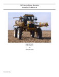
1
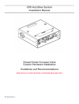
GPS AutoSteer System
Installation Manual
Open Center Load Sense Valve
Hardware Installation
THIS MANUAL IS FOR TRAINED AUTOSTEER DEALERS ONLY
PN: 602-0036-02-C
LEGAL DISCLAIMER
Note: Read and follow ALL instructions in this manual carefully before installing or operating the AutoSteer system.
Note: Take careful note of the safety information in the Safety Information section and throughout this manual.
The manufacturer disclaims any liability for damage or injury that results from failure to follow the instructions and warnings
set forth herein.
Please take special note of the following warnings:
1. There is NO obstacle avoidance system included in the manufacturer’s product. Therefore, users must always have an
operator on the equipment when the AutoSteer system is in use to look for any obstacles including people, animals, trees,
ditches, buildings, etc.
2. During installation of the AutoSteer system and during the Calibration and Tuning processes the vehicle's wheels turn from
side to side and the vehicle moves. Be sure that all people and obstacles are clear of the vehicle before installation, calibration and tuning, or use of the AutoSteer system.
3. Use of the AutoSteer system is NOT permitted while the vehicle is on public roads or in public areas. Ensure that the system is OFF before driving on roads or in public areas.
ii
AutoSteer System
Required Tools
This list consists of the tools required to complete the installation. The installer is assumed to have a complete set of common
installation tools.
5000 psi Pressure Gauge with a female quick
1/8" Allen wrench
coupler for diagnostic ports. A liquid filled pressure
gauge with a long hose reaching the cab is preferred.
1/2" open wrench
Portable drill with assortment of drills up to 3/8"
diameter.
3/16" Allen wrench
3/4" open wrench
Oil pan for collecting oil when hoses are opened.
1/4" Allen wrench
11/16” open wrench
Clean rags for cleaning parts and oil spills.
5/16" Allen wrench
15/16” open wrench
1" open wrench
Additional Parts to Be Fabricated
The parts listed below must be fabricated as needed for the current installation.
1. Brackets for mounting the hydraulic valve on the vehicle (for special applications only).
2. Hydraulic hoses with ORFS fittings (O-Ring Face Seal) on one end to fit the AutoSteer valve and fittings that match the
vehicle’s hose fittings on the other end.
Note: Use only high quality hydraulic hoses rated for at least 3000psi (210 Bar) working pressure. Do not mix hoses and
fittings from different brands.
Hardware Installation Manual
iii
Safety Information
Warning Alerts
The AutoSteer system installer and manufacturer disclaim any responsibility for damage or physical harm caused by failure to
adhere to the following safety requirements:
•
•
As the operator of the vehicle, you are responsible for its safe operation.
The steering system is not designed to replace the vehicle’s operator.
Note: Verify all screws, bolts, nuts, hose connections and cable connections are tight after AutoSteer system installation.
WARNING
To prevent accidental death or injury from being run over by
the vehicle, never leave the vehicle's operator chair with the
AutoSteer engaged.
WARNING
High-Pressure Fluid Hazard
Read this manual before installation. Wear hand and eye
protection while performing hydraulic system maintenance.
Relieve hydraulic system pressure before servicing the
hydraulic system. Tighten all hydraulic connections before
pressurizing.
WARNING
To understand the potential hazards associated with the
operation of AutoSteer equipment read the provided
documentation before installing the AutoSteer system on a
vehicle.
iv
AutoSteer System
WARNING
To prevent the accidental engagement of AutoSteer and loss
of vehicle control while driving on roads, shut down the
AutoSteer system (exit the program). Never drive on roads
or in public areas with the AutoSteer system turned on.
WARNING
Do not stand close to the wheels and do not move the
vehicle while you are adjusting the relief valve. Turn off the
engine and engage the parking brake before standing under
or next to the vehicle.
Vehicle Requirements
•
The vehicle must have an Open Center steering orbitrol with oil flow that does not exceed 15 GPM (56 LPM) and a
maximum pump pressure that does not exceed 3000 psi (210 bar).
•
The vehicle steering and hydraulic systems must be in good working order before installing the AutoSteer system. Check
for loose or worn parts. Before installing the AutoSteer system drive the vehicle and confirm it steers straight and the
wheels can be turned from lock to lock. Check the steering system hydraulic hoses and connections to ensure there are no
oil leaks.
The vehicle electrical system and battery must be in good working order.
The vehicle should be fully cleaned before installing the AutoSteer system. A clean vehicle improves the overall
installation and cable routing and also reduces the chance for oil contamination when the hydraulic connections are opened.
It is important to clean the area around the steering unit (Orbitrol), under the cab and behind the rear cab cover.
•
•
Hardware Installation Manual
v
Important Information
Note: Verify all screws, bolts, nuts, hose connections and cable connections are tight after the final installation of the
AutoSteer system on the vehicle.
Technical Support
Refer to your owner's manual for technical support information.
Contact Information
Refer to your owner's manual for contact information.
Copyright © 2009 All Rights Reserved.
vi
AutoSteer System
Table of Contents
Chapter 1
Introduction ...................................................................................................................... 1
Introduction to Open Center Steering Systems . . . . . . . . . . . . . . . . . . . . . . . . . . . . . . . . . . . . . 1
Application. . . . . . . . . . . . . . . . . . . . . . . . . . . . . . . . . . . . . . . . . . . . . . . . . . . . . . . . . . . . . . . . . 1
About Open Center Steering Systems . . . . . . . . . . . . . . . . . . . . . . . . . . . . . . . . . . . . . . . . . . . . 1
How to Identify an Open Center Steering System. . . . . . . . . . . . . . . . . . . . . . . . . . . . . . . . . 2
Open Center Valve Theory of Operation. . . . . . . . . . . . . . . . . . . . . . . . . . . . . . . . . . . . . . . . 3
Common Vehicles with Open Center Valves . . . . . . . . . . . . . . . . . . . . . . . . . . . . . . . . . . . . . . 5
Chapter 2
Installation Overview ....................................................................................................... 7
Vehicle Requirements for Standard Installation . . . . . . . . . . . . . . . . . . . . . . . . . . . . . . . . . . . . 7
Steering Valve Kit Components . . . . . . . . . . . . . . . . . . . . . . . . . . . . . . . . . . . . . . . . . . . . . . . . 8
Installation Overview. . . . . . . . . . . . . . . . . . . . . . . . . . . . . . . . . . . . . . . . . . . . . . . . . . . . . . . . . 9
Valve and Bracket Mounting Positions . . . . . . . . . . . . . . . . . . . . . . . . . . . . . . . . . . . . . . . . . . 11
Hose Adapter Specifications . . . . . . . . . . . . . . . . . . . . . . . . . . . . . . . . . . . . . . . . . . . . . . . . . . 11
Hole Patterns for Mounting the Valve . . . . . . . . . . . . . . . . . . . . . . . . . . . . . . . . . . . . . . . . . . . 12
Chapter 3
Installation Procedure .................................................................................................... 13
Installation Procedure . . . . . . . . . . . . . . . . . . . . . . . . . . . . . . . . . . . . . . . . . . . . . . . . . . . . . . . 13
Relief Valve Adjustment . . . . . . . . . . . . . . . . . . . . . . . . . . . . . . . . . . . . . . . . . . . . . . . . . . . . . 16
Installation with Pressure in the Tank Line . . . . . . . . . . . . . . . . . . . . . . . . . . . . . . . . . . . . . . . 17
Installation with Manual Steering Relief Pressures above 2320psi . . . . . . . . . . . . . . . . . . . . 19
Drain Plate Installation Procedure . . . . . . . . . . . . . . . . . . . . . . . . . . . . . . . . . . . . . . . . . . . . 19
Examples of Open Center Valve Installations . . . . . . . . . . . . . . . . . . . . . . . . . . . . . . . . . . . . . 21
Examples of Open Center Steering Units (Orbitrols) . . . . . . . . . . . . . . . . . . . . . . . . . . . . . . . 22
Chapter 4
Servicing the Open Center Valve .................................................................................. 25
Required Tools . . . . . . . . . . . . . . . . . . . . . . . . . . . . . . . . . . . . . . . . . . . . . . . . . . . . . . . . . . . . 26
Removing Plugs with the Allen Key . . . . . . . . . . . . . . . . . . . . . . . . . . . . . . . . . . . . . . . . . . . . 27
Adjusting the Pressure Relief Valve . . . . . . . . . . . . . . . . . . . . . . . . . . . . . . . . . . . . . . . . . . . . 28
Replacing the Relief Valve Cartridge . . . . . . . . . . . . . . . . . . . . . . . . . . . . . . . . . . . . . . . . . . . 29
Removing the DPS2 Cartridge . . . . . . . . . . . . . . . . . . . . . . . . . . . . . . . . . . . . . . . . . . . . . . . . 30
LS Drain Plug Removal or Installation . . . . . . . . . . . . . . . . . . . . . . . . . . . . . . . . . . . . . . . . . . 31
LS Drain Orifice Replacement or Cleaning . . . . . . . . . . . . . . . . . . . . . . . . . . . . . . . . . . . . . . . 32
Removing or Replacing the LS Damper Orifice . . . . . . . . . . . . . . . . . . . . . . . . . . . . . . . . . . . 34
Damper Orifice Spares . . . . . . . . . . . . . . . . . . . . . . . . . . . . . . . . . . . . . . . . . . . . . . . . . . . . 36
Chapter 5
Troubleshooting ............................................................................................................. 39
Manual steering is not Working after Installing AutoSteer with the Open Center Valve . . . . 39
Manual Steering is Working but in AutoSteer Mode the Wheels do not Turn . . . . . . . . . . . . 39
Steering is Working in Both Manual and AutoSteer Modes but Pump is Noisy or Oil is Overheating
40
The Hydraulic System is Noisy in AutoSteer Mode and Chatter can be Heard . . . . . . . . . . . 40
The Hydraulic System is Noisy in AutoSteer Mode with the LS Damper Orifice Installed . . 40
The Hydraulic System is Noisy When the Engine is Running Without AutoSteering or Manually
Steering . . . . . . . . . . . . . . . . . . . . . . . . . . . . . . . . . . . . . . . . . . . . . . . . . . . . . . . . . . . . . . . . . . 40
AutoSteer is Slow or Wheels are not Turning . . . . . . . . . . . . . . . . . . . . . . . . . . . . . . . . . . . . . 41
Hardware Installation Manual
vii
The Oil Temperature is Too High . . . . . . . . . . . . . . . . . . . . . . . . . . . . . . . . . . . . . . . . . . . . . . 41
Manual Steering and AutoSteer Become Slower Over Time . . . . . . . . . . . . . . . . . . . . . . . . . 41
AutoSteer Becomes Slower Over Time . . . . . . . . . . . . . . . . . . . . . . . . . . . . . . . . . . . . . . . . . . 41
Open Center Valve is leaking . . . . . . . . . . . . . . . . . . . . . . . . . . . . . . . . . . . . . . . . . . . . . . . . . 41
viii
AutoSteer System
1
Introduction
This Introduction chapter information is provided in the following sections:
•
•
•
•
Introduction to Open Center Steering Systems
Application
About Open Center Steering Systems
• How to Identify an Open Center Steering System
• Open Center Valve Theory of Operation
Common Vehicles with Open Center Valves
Introduction to Open Center Steering Systems
The AutoSteer Open Center Valve Kit was designed for installing the AutoSteer Closed Center Valve (PN 500-0008-02) and
High Flow Valve (PN 500-0016-04) on vehicles that use an Open Center steering system. These steering systems are typically
found on some combine harvesters, some sprayers, smaller tractors and older tractors. The system is known as Open Center
because the steering unit (Orbitrol) is Open and returns the pump’s oil flow to Tank when it is in the Center or neutral position.
These systems are also known as Fixed displacement pumps because the gear pump is always circulating oil in the system at a
rate proportional to the engine speed. The steering circuit oil flow is proportional to the engine speed.
Note: The Open Center Valve #500-0216-01 is rated for maximum oil flows up to 15 gallons/minute (56 LPM) to avoid
possible pump damage and oil heating. Do not install on vehicles that have a steering pump with oil flow greater than 15
GPM at maximum engine speed.
Application
The open center valve describes in this manual must only be used in conjunction with the following AutoSteer valves:
•
•
PN: 500-0008-02 – Closed Center AutoSteer Valve
PN: 500-0016-04 – High Flow AutoSteer Valve
This manual only describes the open center valve installation. Refer to the Hardware Installation manual provided with your
AutoSteer installation kit to complete the AutoSteer installation.
About Open Center Steering Systems
Open Center Steering Systems typically use a small fixed displacement gear pump for providing oil to the steering system. The
pump will sometimes be used for other functions such as moving spray booms. The pump is driven directly by the engine or
Hardware Installation Manual
1
How to Identify an Open Center Steering System
the main drive shaft in the transmission. The pump is always pumping oil at a flow rate that is proportional to the engine speed.
The gear pump oil pressure varies according to demand as follows:
1. When the vehicle is not being steered, the oil flows at a low pressure from the gear pump towards the steering unit
(Orbitrol) and back to the Tank (reservoir). The oil passes freely across the Orbitrol and back to Tank. The oil is always
flowing around the steering circuit while the engine is running. Oil flow is proportional to engine speed.
2. When the steering wheel is turned, the oil flows from the pump towards the steering unit where it gets directed towards the
steering cylinder to turn the wheels. The steering unit’s spool opens an oil path to the steering cylinder and partially closes
the normal return path to Tank in order to build up pressure for moving the wheels. The oil from the opposite steering
cylinder flows towards the Orbitrol and then returns to tank as low pressure oil in the Orbitrol’s return line. See Figure 1-1.
Figure 1-1
Open Center Steering System
How to Identify an Open Center Steering System
Before installing the AutoSteer Open Center Load Sense Valve you must first confirm that your vehicle has an Open Center
steering system and if the oil flow is not more than 15 GPM. You can identify an Open Center steering system by either
looking at the hydraulic diagram provided by the vehicle manufacturer or by identifying some key components on the vehicle.
Both of these methods are explained in the following sections.
View the Vehicle’s Hydraulic Diagram
•
•
•
•
•
•
2
The steering oil pump is usually a fixed displacement Gear pump.
The pump pressure line is connected directly to the steering unit (Orbitrol) without passing through a Priority Valve.
The steering unit only has 4 hoses (Pressure, Return, Right and Left) and does not have a small Load Sense hose.
The spool diagram inside the steering unit shows that pressure returns to Tank when the spool is in the center (neutral)
position.
The diagram does not show or mention Load Sense (LS) lines between the steering unit and the pump or Priority Valve.
A relief valve is always used and is typically built into the steering unit but can sometimes be built inside the pump block
as part of the pump. The Relief Valve can also be a separate component installed between the pump and the Orbitrol.
AutoSteer System
Open Center Valve Theory of Operation
Inspect the Vehicle
•
The steering unit only has four hoses of equal diameter and is missing the smaller Load Sense hose.
Note: On some Open Center vehicles the steering unit has five hoses because the auxiliary hydraulics get their oil
from the steering unit through a Power Beyond feature built into the Orbitrol. Orbitrol hoses can sometimes be of
different diameters on the Pressure, Tank, Right and Left ports.
•
•
•
The steering oil pump is small and is mounted directly on the side of the engine or on the main transmission shaft. The
steering pump is typically a simple Gear Pump used only for steering.
The steering oil pump is very simple and only has two hoses; a Pressure hose taking oil to the steering unit and a larger
diameter suction hose receiving oil from the reservoir. The reservoir can be a separate tank or integrated into the
transmission housing.
There is no priority valve between the pump and the steering unit so the pressure hose goes directly from the gear pump to
the steering unit.
Note: A pressure relief valve can sometimes be found along the pressure line.
•
Some vehicles have a fixed displacement pump sending oil to the steering unit through a Priority Valve which is piloted by
a load sense line coming from a closed center steering unit. At first these vehicles will look like an Open Center steering
system because they have a gear pump, but they are really Closed Center as far as the steering unit is concerned.
Open Center Valve Theory of Operation
The Open Center Load Sense Kit includes a valve which transforms a simple Open Center hydraulic system into a Load Sense
oil supply providing oil pressure on demand to the AutoSteer steering valve. The Open Center valve provides the oil pressure
and oil flow for AutoSteer and is used in addition to the normal AutoSteer valve. See Figure 1-2.
The main component of the valve is the DPS2 (Differential Pressure Sensing) cartridge valve that automatically adjusts the
pump pressure according to the pressure required by the AutoSteer steering valve. The AutoSteer valve has a Load Sense port
which sends a pilot oil pressure signal to the LS port on the Open Center valve. This Load Sense pressure is the actual pressure
used by the AutoSteer valve to turn the wheels. The DPS2 valve responds to the Load Sense pressure and moves an internal
spool to partially close the passage of oil to the manual steering unit until the pump pressure builds up and reaches the load
sense pressure plus the pressure value of the DPS2 cartridge spring (this value is stamped on the DPS2 cartridge in the part
number and is either 40, 80 or 160psi).
The DPS2 valve always keeps the pump pressure slightly above the Load Sense pressure being required by the AutoSteer
steering valve. When the tractor is in manual steering mode, the DPS2 valve enables the free flow of oil across to manual
steering. The standard DPS2 cartridge installed is 160psi and is rated for a maximum flow of 15 GPM (15 gallons/minute).
AutoSteer has optional 80psi and 40psi cartridges for slower steering response or lower pressure systems on smaller vehicles.
A Pressure Relief cartridge valve is built into the Open Center Valve to protect the pump from over pressure by bleeding off
excessive pressure back to Tank. The Pressure Relief valve can be adjusted from 250psi to 3500psi by turning a screw and is
rated for maximum oil flows up to 30 GPM (30 gallons/minute).
The Open Center Load sense kit uses two small orifices for load sense pressure control. One orifice bleeds oil from the Load
Sense line back to Tank so the load sense pressure drops to zero when AutoSteer does not require pressure. This prevents the
Hardware Installation Manual
3
Open Center Valve Theory of Operation
Load Sense line from remaining pressurized and creating oil pressure through the DPS2 valve (stroking up) when oil pressure
is not required for steering. A second orifice dampens the Load Sense pressure spikes to avoid chatter on the DPS2 valve.
The Open Center valve is designed so all hose fittings on one side connect to the AutoSteer valve while all hose fittings on the
opposite side connect to the vehicle. This helps avoid incorrect hose connections and simplifies hose routing.
Figure 1-2
4
Hydraulic Diagram and Port Identification (Valve # 500-0216-01)
AutoSteer System
Common Vehicles with Open Center Valves
Common Vehicles with Open Center Valves
Table 1-1
Common Open Center Valve Vehicles
Open Center Vehicles
JD-6700 Sprayer
Allis Chalmers 8070 tractor
Rogator 554 Sprayer
Hagie 2100 Sprayer
Rogator 854 Sprayer
Krone Forage Harvester
JD-9650/9660 CTS Combine
Kubota M96 tractor
JD-5225 Tractor
Kubota M105X Tractor
JD-9650/9860 STS Combine
MT-455B tractor (some versions)
JD-6700 Sprayer
Note: The vehicles listed in Table 1-1 are typical examples of farm vehicles that may have an open center steering
system. Always confirm the vehicles has an open center steering system before proceeding with the installation of this
valve.
Hardware Installation Manual
5
Common Vehicles with Open Center Valves
6
AutoSteer System
2
Installation Overview
The Installation Overview chapter information is provided in the following sections:
•
•
•
•
•
•
Vehicle Requirements for Standard Installation
Steering Valve Kit Components
Installation Overview
Valve and Bracket Mounting Positions
Hose Adapter Specifications
Hole Patterns for Mounting the Valve
Vehicle Requirements for Standard Installation
For a standard installation, the vehicles steering system must meet the following criteria:
•
•
•
•
Steering Orbitrol must be Open Center
Steering pump flow must be 15 GPM (56 LPM) or less at high idle.
Pressure on the Orbitrol’s Tank line must be low, or less than approximately 100psi.
Maximum pressure for manual steering must be 2320psi or less
Hardware Installation Manual
7
Steering Valve Kit Components
Steering Valve Kit Components
Figure 2-1
Steering Valve Kit Components (PN: 200-0273-02)
Table 2-1
Installation Kit Components (PN: 200-0273-02)
8
Item
Component
Part Number
1.
VALVE OPEN CENTER LOAD SENSE 15 GPM
500-0216-01
2.
INSTALL GUIDE OPEN CENTER VALVE KIT
602-0036-02
3.
HOSE 1/2" X 20" -8F X -8F ORFS
502-0168-01
4.
HOSE 1/4" X 20" -4F X -4F ORFS
502-0169-01
5.
BRACKET OPEN CENTER VALVE
202-0201-01
AutoSteer System
Installation Overview
Installation Overview
1. Identify the main parts of a typical Open Center steering system before the AutoSteer valve is installed. See Figure 2-2.
Note: The AutoSteer Open Center valve is installed along the existing vehicle steering Pressure and Return hoses.
Hose lengths might vary according to the vehicle model and require new hoses.
Figure 2-2
Hose Connections Before Installing Open Center Load Sense Valve
Hardware Installation Manual
9
Installation Overview
2. See Figure 2-3 for correct hose connections after the AutoSteer steering valve and Open Center Valve are installed.
Note: You must fabricate custom high pressure hoses for connecting the system. All hoses should be rated for 3000psi
working pressure and ORFS fittings should be used on the hose ends connecting to the AutoSteer valve. The hose
fittings that connect to your vehicle must match the type of fittings found on your vehicle (ORFS, JIC, DIN etc…).
Note: Figure 2-3 identifies the port names stamped on the Open Center valve block, the main hose connections and
the direction of oil flow.
Note: The LS Drain Plug must not be installed in the Open Center Valve for this standard installation.
Figure 2-3
10
Hose Connections After Installing Open Center Load Sense Valve
AutoSteer System
Valve and Bracket Mounting Positions
Valve and Bracket Mounting Positions
A special AutoSteer valve bracket enables you to mount the Open Center valve directly on either the AutoSteer Small Valve
(PN 500-0008-02) or High Flow Valve (PN 500-0016-04) without having to drill additional holes on the vehicle. You can
change the mounting position of the bracket and valve as shown in Figure 2-4 according to vehicle space.
You can also mount the Open Center valve directly on the vehicle frame or mount the valve on the bracket and secure the
bracket directly to the vehicle. You can also modify the bracket as required for your installation.
If you mount the two valves side-by-side as shown in Figure 2-4, you can use the three 20” jumper hoses provided in your kit
to interconnect the Pressure, Return and Load Sense ports on the two valves following the hose diagrams in this manual.
Longer hoses are required if you install the Open Center valve further away from the main AutoSteer valve.
Figure 2-4
Valve and Bracket Mounting Positions
Hose Adapter Specifications
The AutoSteer Open Center valve uses standard ORFS (O-Ring Face Seal) hose adapters providing excellent protection
against leaks and connect to hose fittings which are readily available on the market. Make your hoses with fittings matching
the valve hose adapters installed. The #8 adapters are threaded into valve block standard SAE -8 ports. The #4 adapters are
threaded into valve block standard SAE -4 ports. You can replace the threaded hose adapters to match other types of hose
fittings if you prefer (ex: JIC, DIN).
Ports T1 and DR are not used in standard applications and are delivered from the factory with steel caps. Remove these caps
and connect your hydraulic hoses when required for special applications according to the recommendations in this manual.
The GP port uses an industry standard SAE J1502 quick coupler nipple that enables the connection of standard pressure
gauges available for farm vehicles and tractors.
Table 2-2
Hose Adapter Specifications
Port
Adapter
P
-8 ORFS Male
Hardware Installation Manual
11
Hole Patterns for Mounting the Valve
Port
Adapter
LS
-4 ORFS Male
T1
-4 ORFS Male + -4 ORFS Cap
AT
-8 ORFS Male
P1
-8 ORFS Male
T
8 ORFS Male
DR
-4 ORFS Male + -4 ORFS Cap
AUX
-8 ORFS Male
GP
1/8” Coupler Nipple (SAE J1502)
Hole Patterns for Mounting the Valve
Note: If you use the valve bracket supplied in your kit, you do not need to drill mounting holes on the vehicle.
The hole patterns needed for mounting the Open Center Valve are shown in Figure 2-5. Use these holes to mount the valve to
a steel bracket or directly to the vehicle:
1. Drill two 3/8” holes at the spacing shown in Figure 2-5 for mounting the valve to a steel bracket or directly to the vehicle.
2. Secure the valve with the two 5/16” x 4-1/2” bolts provided in the kit.
3. The valve position should allow easy access for measuring pressure on the GP port and adjusting the Relief Valve.
Figure 2-5
12
Valve and Bracket Mounting Positions
AutoSteer System
3
Installation Procedure
The Installation Procedure chapter information is provided in the following sections:
•
•
•
•
•
•
Installation Procedure
Relief Valve Adjustment
Installation with Pressure in the Tank Line
Installation with Manual Steering Relief Pressures above 2320psi
• Drain Plate Installation Procedure
Installation with Manual Steering Relief Pressures above 2320psi
Examples of Open Center Steering Units (Orbitrols)
Installation Procedure
1. Before you start the installation you must clearly identify the vehicle as having an OPEN CENTER steering system with a
pump flow that does not exceed 15 GPM (56 LPM).
Note: If you are uncertain about the steering system type, ask your vehicle dealer or manufacturer to determine if it is
an open center system.
2. Identify the main steering components on the vehicle such as the steering oil pump, manual steering unit (Orbitrol),
Pressure line, Return line, oil reservoir, pump suction line and steering lines connected to the Right and Left steer
cylinders.
3. Install the two valves (AutoSteer valve and Open Center valve) on the vehicle using steel brackets if necessary.
Note: The valves are normally installed in a position between the steering pump and the steering Orbitrol. The valve
positions must provide easy hose routing. Hoses must not pass close to moving or hot parts. On some vehicles the
valves can be bolted directly to the vehicle frame.
4. Before you connect hoses to the valve, you must configure the valve for a standard installation.
Hardware Installation Manual
13
Installation Procedure
Note: If a drain plug has already been pre-installed in your valve, you must remove it. This standard installation does
not require the drain plug and if the drain plug is installed there will be pump over pressure and oil heating. Refer to
the LS Drain Plug Removal or Installation section on page 31 for specific instructions on how to remove the drain
plug.
5. Connect a pressure hose between the pump pressure port and the Open Center valve P1 Port. See Figure 2-3.
6. Connect a hose between the Open Center valve P Port and the AutoSteer Valve Pressure port. See Figure 2-3.
7. Connect a hose between AutoSteer Valve Return port and the Open Center valve AT Port. See Figure 2-3.
8. Connect a hose between the Open Center valve AUX Port and the Orbitrol Pressure port. See Figure 2-3.
9. Connect a hose between the Open Center valve T Port and the Orbitrol Tank line towards Tank. You must install a Tee
connector on the vehicle’s steering Tank line in order to connect the hose coming from T port. This hose connection is very
important because it drains the excess pressure from the Relief Valve towards Tank. See Figure 2-3.
Note: Immediate pump damage will occur if the Open Center Valve P1 and T hoses are inverted. Ensure the pump
Pressure hose is actually connected to the P1 port and a Tank/Return line is connected to the T port before starting the
engine. When these two important hoses are correctly installed, the pump is protected by the relief valve inside the Open
Center Valve. The relief valve and DPS2 valve do not allow reverse oil flow if these two hoses are inverted and
immediate pump damage will occur. Double check your hose connections before starting the engine.
10. Connect a hose between the AutoSteer Valve Load Sense port and Open Center valve LS Port. See Figure 2-3.
11. Connect a hose from the Orbitrol Left steering port to the AutoSteer Valve SL port.
12. Connect a hose from the AutoSteer Valve LEFT port to the LEFT Steering Cylinder. See Figure 2-3.
13. Connect a hose from the Orbitrol RIGHT steering port to the AutoSteer Valve SR port. See Figure 2-3.
14. Connect a hose from the AutoSteer Valve RIGHT port to the Right Steering Cylinder. See Figure 2-3.
Note: For some hose connections you can use the existing hoses from the vehicle if they have sufficient length and
correct fittings matching the AutoSteer valve.
Note: Wrong hose connections on the Open Center valve result in over pressure and severe damage to the gear pump on
the vehicle. Check the correct operation of the Pressure Relief Valve using a pressure gauge before turning on the
AutoSteer system.
15. When starting the engine for the first time after completing the installation, momentarily crank the engine without letting it
start. Repeat this several times to purge the air from the hoses while observing the pressure gauge.
14
AutoSteer System
Installation Procedure
Note: The pressure should remain very low (<400psi) while cranking the engine. If you see a pressure spike or if the
starter motor appears to be slow and overloaded, the hoses may be inverted and the pump may be overloaded. Do not
start the engine under these conditions. Check all hose connections, especially the Pressure and Tank lines. Once the
engine is started, immediately check for oil leaks at all hose connections. Turn the engine off immediately if you
observe oil leaks or hear noise from the hydraulic system or pump.
16. Check if the Relief Valve is working correctly after opening the pressure adjustment screw completely counter-clockwise
and turning the steering wheel so the wheels are pushing against the right or left stops (See Figure 1-2).
Note: With the pressure adjustment screw turned counter clockwise there should be a very low pressure reading
(0-200 psi) and the wheels will not move. If you turn the adjustment screw clockwise you should notice the relief
pressure increasing. If the adjustment screw changes the pressure reading you know the AutoSteer Relief Valve is
correctly installed and working. If the AutoSteer Relief Valve is working, you can proceed with the installation.
17. You must adjust the AutoSteer Pressure Relief Valve to a pressure about 100psi above the existing relief valve on the
vehicle.
Note: To measure the original relief pressure on the vehicle you must first adjust the AutoSteer Relief Valve to a high
maximum pressure (Approx. 3600psi) by turning the adjustment screw fully clockwise. Then manually turn the wheels
against the right or left stops using the steering wheel while measuring the pressure on the GP port. The measured
pressure will be the original vehicle steering Relief Pressure.
Note: The vehicle’s original pressure Relief Valve is usually built into the steering Orbitrol but it can also be built into
the pump. When the vehicle’s pressure Relief Valve opens, you normally hear a characteristic “hissing” noise as the
oil reaches maximum pressure and returns to Tank through the Relief Valve. Most vehicle have Relief Valves adjusted
between 2000 psi and 3000psi but some small utility vehicles and tractors can have relief pressures as low as 1200psi.
18. After you have measured the vehicle’s Relief Valve pressure setting, turn the screw on the AutoSteer Relief Valve until it is
threaded about half way out. This corresponds to a safe lower intermediate pressure before starting final adjustments.
19. Proceed to adjust the AutoSteer Relief Valve to a pressure about 100psi above the original vehicle relief pressure as
described below.
20. To adjust the AutoSteer Relief Valve you must measure pressure at the GP port while making a Hard Left or Hard Right
turn against the wheel stops using the Hydraulic Valve window from the Steering Components Window in the Autosteer
Hardware Installation Manual
15
Relief Valve Adjustment
software. You must adjust the screw on the AutoSteer Relief Valve until you get a pressure reading 100psi above the
original vehicle relief pressure.
Note: For example, if the vehicle’s original relief valve is 2500psi, you must adjust the AutoSteer Relief Valve to
approximately 2600psi. Tighten the jam nut on the AutoSteer Relief Valve after the pressure adjustment is completed.
Note: If the vehicle has a Relief Valve built into the pump, you cannot adjust the AutoSteer Relief Valve pressure
above the vehicle’s relief pressure. In this case, adjust the AutoSteer Relief Valve 100psi below the original relief
valve pressure. The important issue is not to adjust the AutoSteer relief valve pressure to the exact original relief
pressure because this could cause some pressure instability and audible chatter when the wheels hit the stops.
21. Proceed with normal AutoSteer testing and calibration according to the AutoSteer installation manual.
22. Check manual steering, AutoSteer, and manual kickout after the installation is completed.
23. Drive the vehicle with manual steering and then with AutoSteer.
24. Check for audible chatter which is a vibration noise caused by the hydraulic system.
25. If chatter is heard in AutoSteer mode you must install a smaller DAMPER ORIFICE in the Open Center valve according to
Figure 1-2.
Relief Valve Adjustment
Figure 3-1 shows a relief valve adjustment. The pressure gauge is installed and an Allen key is being used to turn the
adjustment screw.
Figure 3-1
16
Relief Valve Adjustment
AutoSteer System
Installation with Pressure in the Tank Line
Installation with Pressure in the Tank Line
Some vehicles such as John Deere combines have some pressure in the Tank line because the return oil does not go directly to
Tank but instead serves other functions before it returns to Tank. This generates back-pressure in the Return to Tank line. You
can verify the return line has pressure by measuring the oil pressure on the return line with the engine running at high idle
(~2000 rpm). The Return oil pressure should be less than ~100psi. On some vehicles having a pressure in the return line, you
will find pressures between 200 and 300 psi or more on the return line.
On vehicles with pressure in the return lines you must install the system according to the Figure 3-2. The only difference in
Figure 3-2 is that an internal Load Sense Drain Plug is installed and a Load Sense drain hose is connected from the DR port
directly to Tank. With this setup, the load sense pressure will be drained directly to tank instead of being drained internally
through the open center valve to the steering Return line which has pressure.
Note: If you do not connect the Load Sense drain line per Figure 3-2 on a vehicle with pressure in the return line, the
pump will operate with a higher-than-normal pressure because the Open Center valve DPS2 Valve remains partially
stroked-up all the time due to a higher standby LS pressure.
Note: Some vehicles using the open center oil flow for other functions that are downstream from the Orbitrol may have
intermittent pressure spikes in the Tank line. On these vehicles you may have to activate auxiliary hydraulic functions
(boom control, pumps etc…) to notice a pressure increase in the Tank line.
Hardware Installation Manual
17
Installation with Pressure in the Tank Line
Note: Figure 3-2 identifies the port names stamped on the Open Center valve block and the main hose connections and
the direction of oil flow.
Figure 3-2
18
Hose Connections with Pressure in the Tank Line
AutoSteer System
Installation with Manual Steering Relief Pressures above 2320psi
Installation with Manual Steering Relief Pressures above
2320psi
If you are installing an AutoSteer valve (PN: 500-0008-02 or PN: 500-0016-04) on an open center steering system with
maximum manual steering pressure that exceed 2320psi (160 Bar), you must install an optional drain plate under the
proportional valve as shown in Figure 3-3 and connect your hoses as shown in Figure 3-4. The drain plate and drain hose
purge off the excess Return pressure inside the proportional steering valve and protect the coils from possible damage.
Figure 3-3
Drain Plate Kit (PN: 200-0175-01)
Drain Plate Installation Procedure
1. Install the optional AutoSteer drain plate (PN: 200-0175-01) between the AutoSteer valve block and the DO5 proportional
valve. Use grease to secure the O-Rings during assembly. Secure the drain plate with the four socket head cap Allen screws
provided with the drain plate.
2. Connect the L port on the drain plate side to the Open Center valve T1 port using a 1/4” diameter hose. You must install an
SAE -4 hose adapter on the drain plate to connect your hose to the drain plate.
3. Follow all the hose connections in Figure 3-4.
Hardware Installation Manual
19
Drain Plate Installation Procedure
4. Follow the normal step-by-step standard installation procedures. See the Installation Procedure on page 13.
Note: Figure 3-4 identifies the port names stamped on the Open Center Valve block, the main hose connections and
the direction of oil flow.
Figure 3-4
20
Hose Connections with Drain Plate
AutoSteer System
Examples of Open Center Valve Installations
Examples of Open Center Valve Installations
Figure 3-5
Krone Forage Harvester
Figure 3-6
Rogator 854 Sprayer
Hardware Installation Manual
21
Examples of Open Center Steering Units (Orbitrols)
Figure 3-7
John Deere 5225 Tractor
Examples of Open Center Steering Units (Orbitrols)
Figure 3-8
22
JD-9760 Combine
AutoSteer System
Examples of Open Center Steering Units (Orbitrols)
Figure 3-9
Kubota Tractor
Hardware Installation Manual
23
Examples of Open Center Steering Units (Orbitrols)
24
AutoSteer System
4
Servicing the Open Center Valve
The Servicing the Open Center Valve chapter information is provided in the following sections:
•
•
•
•
•
•
•
•
Required Tools
Removing Plugs with the Allen Key
Adjusting the Pressure Relief Valve
Replacing the Relief Valve Cartridge
Removing the DPS2 Cartridge
LS Drain Plug Removal or Installation
LS Drain Orifice Replacement or Cleaning
Removing or Replacing the LS Damper Orifice
• Damper Orifice Spares
Hardware Installation Manual
25
Required Tools
Required Tools
Figure 4-1 shows the tools required for servicing the Open Center Valve PN: 500-0216-01.
Figure 4-1
26
Required Tools
AutoSteer System
Removing Plugs with the Allen Key
Removing Plugs with the Allen Key
The valve internal and external steel plugs can be difficult to remove after factory assembly. Always use a high quality long
Allen key of the correct size for the hex in the plug. Avoid using hex keys with ball ends. For better leverage and less key
twisting, we recommend using a wrench as shown Figure 4-2 with the correct size Allen socket. All Allen keys are in inch
sizes.
The plugs are easier to remove if the valve is firmly bolted to a structure when you unscrew the plug. The plugs usually require
a firm jolt from a hammer or wooden block on the tool end in order to break it loose.
Do not over tighten the plugs upon assembly. All plugs have a rubber O-Ring seal and over-tightening does not improve the
seal.
Note: The same recommendations also apply to removing and installing valve cartridges.
Figure 4-2
Allen Key
Hardware Installation Manual
27
Adjusting the Pressure Relief Valve
Adjusting the Pressure Relief Valve
To adjust the pressure Relief Valve, loosen the jam nut with the 3/4” wrench and turn the adjustment screw with a 3/16” Allen
key. See Figure 4-3. Measure the maximum pump pressure on a pressure gauge connected to the GP port. Maximum pressure
is reached when wheels are fully turned against the left or right stops.
You can adjust the relief pressure between 250psi (17 Bar) and 3500psi (240 Bar) Note that loosening the screw all the way out
on low flow systems actually brings the pressure down close to zero psi. After the pressure adjustment is completed, tighten
the jam nut while holding the adjustment screw in a fixed position. See Figure 4-3.
Figure 4-3
Adjusting the Pressure Relief Valve
Pressure Gauge
Relief Valve
Adjustment Screw
Jam Nut
28
AutoSteer System
Replacing the Relief Valve Cartridge
Replacing the Relief Valve Cartridge
The Relief Valve cartridge can be easily replaced. To remove, unscrew the cartridge using a 1” wrench. When installing the
cartridge, take care not to damage the O-Rings. See Figure 4-4.
Figure 4-4
Replacing Relief Valve
Relief Valve Cartridge
Hardware Installation Manual
29
Removing the DPS2 Cartridge
Removing the DPS2 Cartridge
Remove the DPS2 cartridge using a 1” wrench. Take care not to damage the O-Ring seals. Install in reverse order. See
Figure 4-5.
The standard DPS2 cartridge is 160psi and should provide good steering response on most vehicles. If you want a slower
steering response, you can replace the 160psi cartridge by an 80psi or 40psi cartridge available from your dealer. See
Figure 4-6.
Figure 4-5
Removing the DPS2 Cartridge
DPS2 Cartridge
Figure 4-6
Available DPS2 Cartridges for Special Applications
160 psi (this is the Standard Cartridge) PN: 500-0064-01
80 psi (slower steering response) PN: 500-0127-01
40 psi (much slower steering response) PN: 500-0070-01
30
AutoSteer System
LS Drain Plug Removal or Installation
LS Drain Plug Removal or Installation
In a normal installation, the LS drain plug is not required and the Load Sense oil drains through an internal orifice towards the
valve Tank (T) port. Check if the drain plug has been pre-installed at the factory and remove it if it is installed. The drain plug
will normally be supplied in a plastic bag along with the valve or threaded into the side of the valve.
If the vehicle has pressure in the Return/Tank line, you will need to install the drain plug in order isolate the Load Sense circuit
from the Return circuit. In this case, the load sense pressure is drained back to Tank through a separate hose connected to the
drain DR port on the valve. This requires installing a hose directly between the DR port and the Tank on the vehicle.
Pressurized Return lines are typically found on vehicles using the Return oil flow to lubricate the gearbox or have other valves
in the steering oil circuit. Refer to specific instructions for Pressurized Return line installations in this manual.
To remove the drain plug, first remove the external plug shown in Figure 4-7 using a 5/16” Allen key. After the external plug
has been removed, you can remove or install the drain plug using a 3/16” Allen key shown in Figure 4-8. The drain plug is a
blind plug without an orifice. Take care not to damage the O-Rings on the plugs.
Figure 4-7
External LS Drain Plug Removal or Installation
External Plug
Hardware Installation Manual
31
LS Drain Orifice Replacement or Cleaning
Figure 4-8
Internal LS Drain Plug Removal or Installation
Internal Plug
LS Drain Orifice Replacement or Cleaning
The Load Sense Drain Orifice is a Disk type orifice and is located under the filter cartridge shown in Figure 4-9. This orifice
must always be installed. To remove the orifice for cleaning, you must first remove the filter cartridge using a 1” wrench. The
orifice disk will fall out easily once the filter has been removed.
Install the orifice in the reverse order. Ensure the flat face is pointed towards the filter while the cone side must be towards the
bottom of the hole. If this orifice is not installed, Load Sense oil will drain directly to tank and LS pressure will not build up
sufficiently for steering.
Note: A magnet may be used to remove the orifice disk if necessary.
The filter mesh prevents this drain orifice from becoming blocked. If this orifice becomes blocked, the load sense pressure will
stay high and the pump pressure will remain high and this could cause oil heating. Inspect this orifice and the filter if you
observe oil overheating or if the pressure line always remains at a high pressure for a long time even when manual steering or
AutoSteer are not being used. When this orifice is not blocked and is working correctly, the pump pressure should drop
immediately whenever the AutoSteer valve is not turning the wheels and manual steering is not being used.
32
AutoSteer System
LS Drain Orifice Replacement or Cleaning
Figure 4-9
LS Drain Orifice Replacement or Cleaning
Drain Orifice Location
Port
0.022” Orifice Disk
Hardware Installation Manual
Orifice Filter Mesh
33
Removing or Replacing the LS Damper Orifice
Removing or Replacing the LS Damper Orifice
A Damper orifice is used to slow down the response of the Load Sense pilot signal on the DPS2 valve and helps eliminate
audible chatter (hydraulic vibration noise) on some vehicles.
The valve will work with or without this orifice but if this orifice is not installed you might hear audible chatter (hydraulic
noise) from the steering system when in AutoSteer mode.
The standard size of this orifice is 0.031”. Vehicles having audible chatter when using this orifice might require a smaller
diameter orifice to eliminate chatter. See Figure 4-13 for available orifice sizes.
1. Remove the external plug using a 1/4” Allen key as shown in Figure 4-10.
Figure 4-10 Remove External LS Damper Orifice Plug
34
AutoSteer System
Removing or Replacing the LS Damper Orifice
2. Remove the internal Orifice Plug using a 1/8” Allen key as shown in Figure 4-11.
Figure 4-11 Remove Internal LS Damper Orifice
Figure 4-12 LS Damper Orifice Removed
Orifice Plug
Hardware Installation Manual
35
Damper Orifice Spares
Damper Orifice Spares
The following damper orifices are available from your dealer as spare parts.
36
AutoSteer System
Damper Orifice Spares
Note: On valves shipped after 04/2010, optional 0.022” and 0.015” diameter orifices are shipped along with the valve as
spare parts and are threaded into the side of the valve for easy access. See Figure 4-14.
Figure 4-13 Available Damper Orifice Spares
Orifice 0.031” SAE #2 (factory installed) PN: 500-0160-01
Orifice 0.022” SAE #2 PN: 500-0300-01
Orifice 0.015” SAE #2 PN 500-0339-01
Figure 4-14 Spare Orifice Location
Spare Orifices
Hardware Installation Manual
37
Damper Orifice Spares
38
AutoSteer System
5
Troubleshooting
The Troubleshooting chapter information is provided in a series of common problems and solutions.
•
•
•
•
•
•
•
•
•
•
•
Manual steering is not Working after Installing AutoSteer with the Open Center Valve
Manual Steering is Working but in AutoSteer Mode the Wheels do not Turn
Steering is Working in Both Manual and AutoSteer Modes but Pump is Noisy or Oil is Overheating
The Hydraulic System is Noisy in AutoSteer Mode and Chatter can be Heard
The Hydraulic System is Noisy in AutoSteer Mode with the LS Damper Orifice Installed
The Hydraulic System is Noisy When the Engine is Running Without AutoSteering or Manually Steering
AutoSteer is Slow or Wheels are not Turning
The Oil Temperature is Too High
Manual Steering and AutoSteer Become Slower Over Time
AutoSteer Becomes Slower Over Time
Open Center Valve is leaking
Manual steering is not Working after Installing AutoSteer
with the Open Center Valve
•
•
•
Check if all hoses are correctly installed per the hose diagram.
Measure pump pressure at the GP port while turning the steering wheel to determine if pump pressure is reaching the Open
Center valve.
The relief valve may be open.
Manual Steering is Working but in AutoSteer Mode the
Wheels do not Turn
•
•
•
•
•
•
Check if all hoses are correctly installed on the correct valve ports.
Check if all cables are correctly connected to AutoSteer valve and system is turned on.
Check if the Drain orifice is installed in the Open Center valve.
Check if steering calibration was performed.
Repeat steering calibration to check if AutoSteer valve turns the wheels.
Measure pump pressure on the GP port to determine if the pump is being stroked up by the AutoSteer valve.
Hardware Installation Manual
39
Steering is Working in Both Manual and AutoSteer Modes but Pump is Noisy or Oil is Overheating
Steering is Working in Both Manual and AutoSteer Modes
but Pump is Noisy or Oil is Overheating
•
•
Check if the LS drain plug is installed in the Open Center valve. This plug is not needed for standard installations and if it
is installed, the pump pressure will always remain high and cause oil heating.
Measure the pump pressure at the GP port. Pump pressure should always remain low (ex: less than 200psi) when AutoSteer
is not turning the wheels and should increase to about 500~1500psi while AutoSteer turns the wheels.
Note: Pump pressure should also stay low in manual steering mode until you turn the steering wheel. If pump pressure
is always high, something is wrong and must be corrected.
•
Check if the LS drain orifice is plugged by dirt. Remove and clean the orifice.
The Hydraulic System is Noisy in AutoSteer Mode and
Chatter can be Heard
•
•
•
•
Check if the LS damper orifice is installed inside the valve.
Check if all hoses are correctly installed.
Secure any loose hoses.
Avoid using hoses that are too long or that can move under pressure.
The Hydraulic System is Noisy in AutoSteer Mode with the
LS Damper Orifice Installed
•
•
•
•
•
You might need a smaller size LS damper orifice. Replace the factory 0.031” damper orifice by the smaller 0.022” or 0.015”
orifice provided attached to the valve.
Check all hose connections. Secure any loose hoses. Avoid using hoses that are too long or that can move under pressure.
Check the AutoSteer relief valve pressure and make sure that it is about 100psi above or below the vehicle’s relief valve
setting.
For normal installations, ensure the LS drain plug is not installed.
Some vehicles may require an accumulator to dampen gear pump pressure spikes to eliminate noise.
The Hydraulic System is Noisy When the Engine is
Running Without AutoSteering or Manually Steering
•
•
•
40
Some vehicles, especially those with a small pump flow and low backpressure in the Tank line may exhibit hydraulic noise
when the engine is running.
Install a smaller LS damper orifice. If the smaller orifice does not eliminate the noise, replace the 160psi DPS2 cartridge
by an 80psi cartridge.
You may also use a 40psi cartridge but steering response will be slower.
AutoSteer System
AutoSteer is Slow or Wheels are not Turning
AutoSteer is Slow or Wheels are not Turning
•
The relief valve setting might be too low and is not allowing sufficient pressure to turn the wheels. Check pump pressure
and adjust the relief valve.
Note: This can also happen if you use a 40psi or 80psi DPS2 cartridge instead of the standard 160psi cartridge on
some vehicles.
•
•
•
•
Install the standard 160psi DPS2 cartridge for faster steering response.
Check the actuator calibration.
Check if the LS drain orifice is not missing inside the valve.
Check the voltage of the vehicle power outlet with the engine running.
Note: Voltages that are less than 13.5V will cause slower steering. Voltages below 12.5V will cause significantly
slower steering.
The Oil Temperature is Too High
•
•
•
•
•
High oil temperatures in Open Center steering system is usually caused by a standby pump pressure that is too high.
Install a pressure gauge and measure the pump’s standby pressure at high idle which should be low.
A blocked LS drain orifice or wrong hose connections may cause a high standby pressure and oil heating.
The AutoSteer Open Center priority valve is rated for 15 GPM maximum oil flow and higher oil flows will cause oil
heating. Small hose diameters on pressure and Tank lines may also cause oil heating.
Use hoses that are equal or larger diameter than the original vehicle hoses.
Manual Steering and AutoSteer Become Slower Over Time
•
•
Check if the jam nut is loose on the relief valve.
Adjust the relief valve and tighten the jam nut.
AutoSteer Becomes Slower Over Time
•
•
•
Internal seals on the DPS2 cartridge may be leaking.
Replace the DPS2 valve cartridge.
Check for dirt in the LS damper orifice that may be partially blocked.
Open Center Valve is leaking
•
Replace O-Ring seals on the component that is leaking.
Hardware Installation Manual
41
Open Center Valve is leaking
Note: Oil contamination is a main cause of hydraulic system failures and valve wear. Maintain the vehicle oil filtration
system in good working order and follow the manufacturers recommendations for oil changes and filter replacements.
Avoid oil contamination during vehicle maintenance.
42
AutoSteer System