1
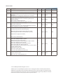
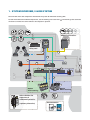
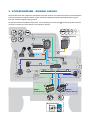
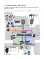
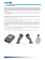
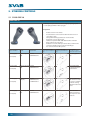
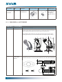
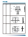
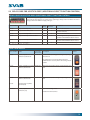
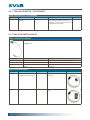
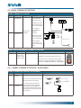
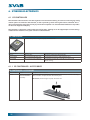
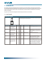
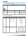
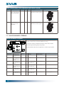
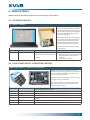
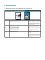
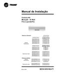
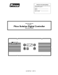
Excavator and Backhoe loader Control GPC
Tiltrotator/Attachments, Wheels, Tracks and additional functions
153000
Application Contents
Revision I
Revision table
Revision
Description
Page
Date
Signature
Authorized
B
Amended in L8 text for properties.
10
130508
FRJA
FRER
C
Added feedback section at the end of the documentation
-
130628
FRJA
FRER
Corrected wrong art. no. and description in wheel steering
activation.
Changed incorrect designation ”bucket lock” to ”tool lock”.
17
D
130916
FRJA
FRJA
-
E
Changed name of the Application Contents.
Added ”additional functions” and function symbols to the
system overviews.
New chapter “Additional Functions”.
Removed trunk cable from 4-hose system overview.
131016
FRJA
FRER
F
New article: Relay card for joystick grips.
New article: Service tool.
L8, New property “Pre-connectorized for GP systems”. Merged
rollers and buttons columns to “Fitted with”.
15
31
10
140218
FRJA
FRER
140328
FRJA
FRER
140821
FRJA
FRER
140916
FRJA
FRER
TRUNK CABLE ACCESSORIES: Changed and added (new article
300975) related cables for attachment plates.
G
H
I
-
21
-
20
Overviews: Added supply for supply pilot valve cables.
Added supply cable on the overviews CAN and 4-hose.
Added info on supply cable 146123.
24
New articles: Dokumentation.
32
Multilingual documentation.
New article: SVAB Hand-Rest L8 146562.
Added info on weld bracket 200333.
Removed steering valve 135007-XXX from adapter 200583.
New article: Adapter LS Eaton 200678.
New article: Adapter plate steering valve 200558.
New articles: CAN cable 147616, 147616-3.
New articles: Wheel steering activation and accessories 200672,
200673, 200674, 200675.
Added info on trunk cables.
New article: Cable support 200373.
New article: User Manuals 630006, 630013.
32
12
20
29
29
29
21
17
20
12
32
New articles: Operator manuals in several languages: 113019,
113020, 113021, 113022.
32
New article: Spacer Ring Hand Rest L8.
14
© 2013 SVAB Hydraulik AB. All rights reserved.
SVAB accepts no responsibility for possible errors in catalogs, brochures and other printed material.
SVAB reserves the right to alter its products without prior notice. This also applies to products already
ordered, provided that such alterations can be made without affecting agreed specifications. All trademarks in this material are the property of their respective owners.
CONTENTS
Ch.
Contents
Page
1.
SYSTEM OVERVIEW, 2-HOSE SYSTEM ..............................................................................................................................5
2.
SYSTEM OVERVIEW – ORIGINAL CAN BUS......................................................................................................................6
3.
SYSTEM OVERVIEW, 4-HOSE SYSTEM ..............................................................................................................................7
4.
INTRODUCTION ...................................................................................................................................................................8
5.
STEERING CONTROLS ...................................................................................................................................................... 10
5.1 SVAB GRIP L8 ........................................................................................................................................................................... 10
5.1.1 SVAB GRIP L8 - ACCESSORIES............................................................................................................................................. 12
5.2 JOYSTICK GRIP CABLES ........................................................................................................................................................ 14
5.3 RELAY CARD FOR JOYSTICK GRIPS (ADDITIONAL DIRECT FUNCTION CONTROL) .......................................... 15
5.4 TOOL LOCK SWITCH .............................................................................................................................................................. 15
5.4.1 TOOL LOCK SWITCH – ACCESSORIES .............................................................................................................................. 16
5.5 TOOL LOCK SWITCH CABLES.............................................................................................................................................. 16
5.6 WHEEL STEERING ACTIVATION .......................................................................................................................................... 17
5.6.1 WHEEL STEERING ACTIVATION - ACCESSORIES ........................................................................................................... 17
6.
STEERING ELECTRONICS ................................................................................................................................................. 18
6.1 GP CONTROLLER .................................................................................................................................................................... 18
6.1.1 GP CONTROLLER - ACCESSORIES ..................................................................................................................................... 18
6.2 CONNECTION CARD CABLE................................................................................................................................................ 19
6.3 CONNECTION CARD APL ..................................................................................................................................................... 19
6.4 CONNECTION CARD APLX FOR WHEEL AND TRACK STEERING............................................................................. 19
6.5 TRUNK CABLE .......................................................................................................................................................................... 20
6.5.1 TRUNK CABLE ACCESSORIES.............................................................................................................................................. 20
6.6 ADDITIONAL FUNCTIONS WITH GPR CONTROLLER .................................................................................................. 21
6.7 GPR CONTROLLER - CAN CABLE ....................................................................................................................................... 21
7.
HYDRAULICS .................................................................................................................................................................... 22
7.1 PILOT VALVE ............................................................................................................................................................................. 22
7.2 SUPPLY/PILOT VALVE’S CABLES ......................................................................................................................................... 24
7.3 VALVE CABLES FOR TRACK STEERING ............................................................................................................................. 25
7.3.1 PILOT VALVE – ACCESSORIES.............................................................................................................................................. 25
7.4 CAN SPLITTER .......................................................................................................................................................................... 26
7.5 CAN CABLE FOR CAN SPLITTER ........................................................................................................................................ 26
7.6 VALVE SOLUTION FOR EXPANSION OF ELECTRO-HYDRAULICS ON THE MACHINE ....................................... 27
7.7 VALVE FOR WHEEL STEERING............................................................................................................................................. 28
7.7.1 VALVE FOR WHEEL STEERING – ACCESSORIES ............................................................................................................. 29
7.8 VALVE CABLES FOR WHEEL STEERING ............................................................................................................................ 30
8.
SERVICE TOOLS ................................................................................................................................................................. 31
8.1 GP CONFIG (COM-KIT) .......................................................................................................................................................... 31
8.2 SVAB SPARE PART KIT TILTROTATOR CONTROL............................................................................................................ 31
9.
DOCUMENTATION ............................................................................................................................................................ 32
9.1 MOUNTING INSTRUCTION, OPERATORS AND USER MANUAL............................................................................... 32
1. SYSTEM OVERVIEW, 2-HOSE SYSTEM
The overview shows the components included in the system for Tiltrotator steering GPC.
To read more about the included components, see the marking in the overview
of contents and has the same number as the chapter in question.
. The marking refers to the list
x
x
x
x
x
Additional functions
6.5
6.1
6.6
5.3
Option
Relay card
5.1
6.7
5.2
6.2
5.4
7.2
5.5
6.3
6.4
6.4
7.1
5.6
7.3
7.8
7.1
7.7
Option
Wheel steering
Option
Track steering
7.6
Valve solutions for
expansion of
additional hydraulics
(replaces pilot valve)
Documentation
9.1
x
2. SYSTEM OVERVIEW – ORIGINAL CAN BUS
The overview shows the components included in the system in those cases where the machine controls the pilot
valve function with its original CAN bus system. Excavator and Backhoe loader Control GPC replaces signals
from the machine’s original steering control.
To read more about the included components, see the marking in the overview
of contents and has the same number as the chapter in question.
. The marking refers to the list
x
x
x
x
x
x
Additional functions
6.5
6.1
6.6
5.3
Option
Relay card
5.2
6.7
5.1
7.2
6.2
5.4
5.5
7.5
ECU
6.4
6.4
5.6
7.4
7.3
7.8
7.7
7.1
Option
Wheel steering
Option
Track steering
Documentation
9.1
3. SYSTEM OVERVIEW, 4-HOSE SYSTEM
The overview shows the components included in the system in those cases where the attachment is to be controlled with a 4-hose solution.
To read more about the included components, see the marking in the overview
of contents and has the same number as the chapter in question.
. The marking refers to the list
x
x
x
x
x
Additional functions
6.1
6.6
5.3
Option
Relay card
5.2
5.1
6.7
6.2
5.4
5.5
7.2
6.3
7.2
6.4
6.4
5.6
7.1
7.3
7.8
7.7
7.1
Option
Wheel steering
Option
Track steering
7.6
Valve solutions for
expansion of
additional hydraulics
(replaces pilot valve)
Documentation
9.1
x
4. INTRODUCTION
The Excavator and Backhoe loader Control GPC application is a freestanding, independent control system for
tiltrotators and attachments that are controlled in a similar way to tiltrotators. The system facilitates flexible and
variable control of the machine’s tiltrotator, and can be expanded with options such as track steering and wheel
steering. This material describes the components that are included in the Excavator and Backhoe loader Control
GPC application.
The system comprises an electronics unit, two joystick grips, a valve for sending out oil to the attachment as
well as associated cabling.
GP Controller is the electronics unit that regulates and controls the steering, and which is configured to provide the operator
with optimum control over the functions. The unit monitors the tool lock and provides a clear warning if the tool is unlocked. This
is done to minimize the risk of personal injury.
Joystick grips with proportional thumb rollers are necessary for efficient control of the tiltrotator. The machine’s original joystick
grips are replaced with grips that have proportional thumb rollers.
A pilot valve (proportional pressure reduction valve with shuttle) is installed in the machine for pilot control of the machine’s
main valve, which in turn sends oil out to the tiltrotator. The pilot control of the machine’s main valve is electro-hydraulic and the
machine operator does not have to control the supply to the tiltrotator with a foot pedal. Instead, the system’s supply is controlled through the same rollers that control the tiltrotator’s functions. This, along with flow requirement control (flow adapted
according to current needs), means that the machine’s various functions do not affect or disrupt each other when they are run
simultaneously.
Excavator and Backhoe loader Control GPC has been developed in accordance with the Machinery Directive, which means that
the system has been risk-assessed and designed to minimize the risk of personal injury. A machine equipped with Excavator and
Backhoe loader Control GPC from SVAB can easily be CE marked.
Excavator and Backhoe loader Control GPC is compatible with the majority of machine and tiltrotator makes on the market.
GP Controller
8
SVAB Grip L8
Pilot valve
SYSTEM SPECIFICATION – EXCAVATOR AND BACKHOE LOADER CONTROL GPC
Supply voltage
9-36V
Operating temperature
-40°C to +70°C
Approved areas of use
Rotor/tilt units for excavators, excavator loaders or backhoes, and as alternative
steering for excavators.
Direct proportional function with performance level up to b per ISO 13849-1.
Approved functions for steering according to the Machinery Directive.
Pilot valve-controlled proportional function (functions that use a proportionally
controlled pilot valve) with performance level up to b per ISO 13849-1.
Wheel steering function with performance level d, category 2 per ISO 13849-1 for
use at maximum speed of 20 km/h per ISO 5010.
Track steering with utilization of direct proportional function as per the description
above.
Max. number of rollers
(Divided between 2 x SVAB Grip L8)
System functions
Tool lock with performance level d per ISO 13849-1.
6
•
•
•
•
•
•
•
•
Tiltrotator and grapple – Proportional steering with thumb roller.
Extra – Proportional steering with thumb roller.
Tool lock – Lockable switch for tool lock.
CDC-W (Wheel steering) – Proportional steering with thumb roller.
CDC-C (Track steering) – Proportional operation with thumb roller.
UI (User Interface) – Alphanumeric display, 8x2 characters and keypad.
Ergonomic handles – Compatible with all joystick bases on the market.
Modular (Expandable system) – CAN bus-based, which makes it easy to expand
with more units to add more functions.
9
5. STEERING CONTROLS
5.1 SVAB GRIP L8
SVAB GRIP L8
SVAB Grip L8 replaces the machine’s original joystick grip and
can be equipped with 3 rollers per grip.
Properties
•
•
•
•
•
•
•
Fitted with
Double sensors in the rollers.
Vacant buttons can be used for other functions and can
cope with 3 amps.
Compatible with all joystick bases on the market.
Ergonomic, easy-to-grip design.
Facilitates operation with both thumb roller and index
finger roller at the same time.
Available in variants with up to three rollers, of which two
are for the thumb and one is for the index finger.
Pre-connectorized for GP systems.
Layout, front right
Layout, rear right
Description
(reverse layout for left-hand
grip)
(reverse layout for left-hand
grip)
(two rollers are always
used for tilt rotator control)
Article number
Name
170100 (right)
Grip L8 1pr 5sw 1 Roller.
(14)
5 OTTO buttons.
Standard joystick
grip.
Grip L8 1pr 7sw 1 Roller.
(14)
7 OTTO buttons.
Variant fitted with
the maximum number of buttons.
Grip L8 1pr 4sw 1 Roller.
FNR (13)
4 OTTO buttons.
1 DATEK Rocker.
Can be combined
with 171200 in order
to achieve a solution
for wheel steering
with forward/reverse
rocker.
Grip L8 1pr 3sw 1 Roller.
(11)
3 OTTO buttons.
Can be used for
compact machines
that only have a few
functions.
171100 (left)
170101 (right)
171101 (left)
170103 (right)
171103 (left)
170105 (right)
171105 (left)
10
Fitted with
Layout, front right
Layout, rear right
Description
(reverse layout for left-hand
grip)
(reverse layout for left-hand
grip)
(two rollers are always
used for tilt rotator control)
Article number
Name
170200 (right)
Grip L8 2pr 5sw 2 Rollers.
(14)
5 OTTO buttons.
Can be used for
wheel or track steering, where an extra
function can also
be controlled at the
same time.
Grip L8 2pr 7sw 2 Rollers.
(14)
7 OTTO buttons.
Can be used for
wheel or track
steering with max.
number of buttons
for additional on/off
functions.
Grip L8 2pr 4sw 2 Rollers.
FNR (13)
4 OTTO buttons.
1 DATEK rocker.
Can be used for
wheel steering with
forward/reverse
rocker.
171200 (left)
170201 (right)
171201 (left)
170203 (right)
171203 (left)
One extra roller
function.
170205 (right)
Grip L8 2pr 3sw 2 Rollers.
(11)
3 OTTO buttons.
Can be used for
compact excavators
with track steering.
Grip L8 2pr 6sw 2 Rollers.
FNR (13)
6 OTTO buttons.
1 DATEK rocker.
Suitable for wheel
steering with forward/reverse rocker.
171205 (left)
170208 (right)
171208 (left)
One extra roller
function and max.
number of buttons.
170300 (right)
Grip L8 3pr 5sw 3 Rollers.
(22)
5 OTTO buttons.
171300 (left)
Can be used for track
steering, with one
extra roller for
one additional function.
170303 (right)
Maximum number
of buttons.
Alternative wheel
steering variant with
index finger rocker.
Grip L8 3pr f/b
1-0-1 4sw (22)
3 Rollers.
4 OTTO buttons.
1 SPDT rocker.
Two extra roller functions and maximum
number of buttons.
11
Article number
Name
Fitted with
170305 (right)
Grip L8 3pr 3sw 3 Rollers.
(22)
3 OTTO buttons.
Layout, front right
Layout, rear right
Description
(reverse layout for left-hand
grip)
(reverse layout for left-hand
grip)
(two rollers are always
used for tilt rotator control)
Can be used for track
steering, with one
extra roller for
one additional function.
171305 (left)
5.1.1 SVAB GRIP L8 - ACCESSORIES
SVAB GRIP L8 - ACCESSORIES
Article number
146562
Name
Hand-Rest L8
Description and Dimensions
SVAB Hand-Rest L8 increases comfort, relieves the hands and reduces the risk of
repetitive strain injuries. The hand-rest improves control of the steering and allows a
flexible adjustment for different hand sizes and personal preferences.
The installation of the hand-rest is easy and can be done by the machine owner.
Installing the hand-rest can be done without disconnecting the joystick cabling.
85
90
000193
17,5
43
180
84
!
Handle adapter
L8 M12, M14 &
M14x1.5
The adapter ball is screwed into the machine’s joystick base and then secured to L8.
3 different dimensions of screw are supplied with this article. M12, M14 and M14x1.5.
8
167110
8
15
3
2
42
12
Article number
167120
Name
Bellows holder L8
with screw
Description and Dimensions
Standard bellows holder made of steel. Makes it possible to secure joystick bellows
to L8. Can also be used with Hand Rest L8.
2
26
R24
4
0
,5
R3
10,80
200572
Bellows washer L8
D=76
Bellows holder adapter that is used together with bellows holder (167120) to adapt
to bellows with the specified dimensions:
76
6
A
Bellows holder adapter that is used together with bellows holder (167120) to adapt
to bellows with the specified dimensions:
R2
0
0
R2
A
A
65
Bellows washer,
Liebherr, machined
32,50
200424-1
A
40,50
6
81
13
Article number
200373
Name
Cable support
joystick base, set of
2 pcs incl. instruction
Description and Dimensions
Brackets which are mounted on the joystick bases and fixates joystick grip cables.
The bracket enhances the quality of the joystick installation since the cables are attached so that the risk of cable damage is better avoided.
C/C 80mm
200714
Spacer Ring Hand
Rest L8
The spacer ring is needed for bellow washers 200572 and 200424-1 if these bellow
washers are to be mounted on an L8 equipped with a hand-rest. The spacer allows
the bellow washer to be mounted correctly and flat against the hand-rest. If the
spacer is missing the bellow washer will have an angled incorrect mounting.
32,50
65
0
R2
40,50
81
76
A
A
5.2 JOYSTICK GRIP CABLES
JOYSTICK GRIP CABLES
For connecting the joystick grip and GP Controller.
Axel
1
El.
Axel
5
One cable is required for each joystick grip.
l2
Axe l.
E 6
l
Axe
Ax
el
Ax
el
X
X
For number of
Length
rollers
2
3m
Article number
Name
146108
Handle cable GP/RT 2x4-pole Microfit 3m
146115
Handle cable GP/RT 3x4-pole Microfit 3m
3
3m
-
146113
Handle cable GP/RT 2x4-pole Microfit 3m
CAN
2
3m
146116
Handle cable GP/RT 3x4-pole Microfit 3m
CAN
3
3m
Cable with CAN bus connection.
Required for systems with CAN
splitter.
Cable with CAN bus connection.
Required for systems with CAN
splitter.
14
Description
-
5.3 RELAY CARD FOR JOYSTICK GRIPS (ADDITIONAL DIRECT FUNCTION CONTROL)
RELAY CARD FOR JOYSTICK GRIPS (ADDITIONAL DIRECT FUNCTION CONTROL)
A relay card for joystick grips is used to advantage when several machine functions is to be controlled directly from buttons or rockers on the joystick grip. Relay cards are available in several
designs, tailored for different supply voltages.
Artikel number Name
Supply
voltage
12V
Controllable
functions
4
146012
Relay card RT Grip 12V
146013
Relay card 12V FNR, 1-2-3
12V
2
146024
Relay card RT Grip 24V
24V
4
146025
Relay card RT Grip 24V Gear FBN D
24V
1
146027
Relay card RT Grip 5V Gear FBN D
5V
1
146030
Relay card RT Grip
5V
4
Description
For 4 on / off -functions.
Provides signal in all 3 positions for 2x
3-position switches.
For 4 on / off -functions.
Provides signal in all 3 positions for 1x
3-position switch. With Deutsch contact.
Provides signal in all 3 positions for 1x
3-position switch. With Deutsch contact.
Standard card for 4 on / off -functions.
5.4 TOOL LOCK SWITCH
TOOL LOCK SWITCH
Article number Name
371053
Panel hole
Description
dimensions
Switch, 2-position 1-1 ratio. 21x41 mm
Contura V, bucket lock
Picture
Standard switch, Carling, for locking and opening
the tool lock.
The switch fits in panel hole with dimensions
22x44 with the accessory “frame for Carling switch”
200341.
371020
Switch, 2-position 0-1 ratio. 22x44 mm
SWF 533, bucket lock
Alternative switch for locking and opening the tool
lock.
370794
Switch, 2-position 0-1 ratio. 22x44 mm
SWF 511, bucket lock
Alternative switch for locking and opening the tool
lock.
370795
Symbol plate red, white
symbol (lock)
370794-01
Switch, 2-position 1-1 ratio. 21x41 mm
Contura II (cat)
Alternative Carling switch.
Suitable for CAT machines.
15
5.4.1 TOOL LOCK SWITCH – ACCESSORIES
TOOL LOCK SWITCH – ACCESSORIES
Article number Name
200341
Frame for Carling switch,
SWF511
Panel hole dimensions Description
Picture
22x44 mm
Frame for Carling switch (371053
Contura V), which allows installation of
Contura V in panel hole with dimensions
22x44 (SWF 511 standard).
5.5 TOOL LOCK SWITCH CABLES
TOOL LOCK SWITCH CABLES
Cable between tool lock switch and APL card.
Length: 2.5m
Article number
302141
Name
Bucket lock switch cable GP/RT, SWF 511
Description
Cable for tool lock switch 370794 (SWF 511).
302142
Bucket lock switch cable GP/RT, SWF 533
Cable for tool lock switch 371020 (SWF 533).
302143
Bucket lock switch cable GP/RT, Carling
switch
Cable for tool lock switch 371053 (Carling Contura V and
Contura II).
TOOL LOCK SWITCH KITS
Article number Name
810449
Tool lock switch with cable,
APL/APL2 Carling Contura V
Length
2.5m
Description
Picture
Carling Contura V tool lock switch
with cable.
371013
2.5m
SWF 511 tool lock switch with
cable.
16
Tool lock switch APL SWF511
5.6 WHEEL STEERING ACTIVATION
WHEEL STEERING ACTIVATION
Art. No.
200672
Name
Interlock Steering GPC 24V
Panel hole dim.
Description
Picture
Kit for safe wheel
steering function.
Conditions for activation and inactivation
can be connected to:
200673
Interlock Steering GPC 12V
21x41mm alt.
22x44mm
- Security gate.
- Steering wheel
(orbitrol).
- Switches.
Also allows connection to the machine
for speed limitation.
000126
The kit includes
circuit breakers, wiring, connectors and
relays.
PANEL SWITCH FOR WHEEL STEERING ACTIVATION
Article number Name
Panel hole dimensions
372041
Switch, 2-posi- 21x41 mm
tion 1-1 ratio.
Contura V, lock.
wheel + SVAB
Description
Switch for activating/deactivating wheel steering.
Picture
SVAB does not supply cabling for this switch.
This switch can be combined with 200341 for
fitting in panel hole with dimensions 22x44, see
chapter “5.4.1 TOOL LOCK SWITCH – ACCESSORIES”.
5.6.1 WHEEL STEERING ACTIVATION - ACCESSORIES
WHEEL STEERING ACTIVATION - ACCESSORIES
Art. No.
200674
Name
Description
Pressure Switch
10-50 bar
Picture
Accessory for kit ”Safe wheel steering
function” (200672 and 200673).
200675
The pressure switch provides the
Pressure Switch kit for safe wheel steering function
10-100 bar
additional functionality. With the
pressure switch the wheel steering is
disabled when the operator turns the
steering wheel.
17
6. STEERING ELECTRONICS
6.1 GP CONTROLLER
GP Controller is the electronics unit that regulates and controls the steering. The unit has wide-ranging configuration options and monitors the tool lock, as well as providing a clear warning if the tool is unlocked. This is
done to minimize the risk of personal injury. The machine operator can switch between different user profiles
via the unit’s keypad and display.
GP Controller is supplied as standard without configuration, although it can be supplied pre-set with settings
suitable for the machines and system solutions indicated below.
GP CONTROLLER
Dimensions (width x height x depth): 94x147x35 mm
Article number
147000
Name
GP Controller
Description
Standard configuration GP Controller.
147000-CANP
GP-Controller CAN pilot valve
Configured for machines with CAN pilot valve.
147000-EWC
GP-Controller, Volvo EWC/ECC
Configured for Volvo EW-C and EW-D machines with
wheel steering.
6.1.1 GP CONTROLLER - ACCESSORIES
GP CONTROLLER - ACCESSORIES
Article number
210000
Name
Attachment plate
Plexi for GP/RT Box
assembly
Description and Dimensions
Attachment plate for installation of GP Controller with contact cover for collecting
cables. Contains complete kit with attachment plate.
Dimensions (width x height x depth): 95x300x8 mm
18
6.2 CONNECTION CARD CABLE
CONNECTION CARD CABLE
For connecting the APL/APLX card and GP Controller.
Article number
147160
Name
Connection card cable GP 1.5m APL
Length
1.5m
Description
-
147161
Connection card cable GP 2.5m APL
2.5m
-
6.3 CONNECTION CARD APL
CONNECTION CARD APL
The connection card connects GP Controller with various tiltrotator models.
Article number
146180
Name
Connection card APL
Description
-
6.4 CONNECTION CARD APLX FOR WHEEL AND TRACK STEERING
CONNECTION CARD APLX FOR WHEEL AND TRACK STEERING
Connection card APLX is used to expand the APL card in order to facilitate connection of wheel
or track steering.
Article number
147181
147180
Name
Description
Connection card APLX Wheel
Connection card for the wheel steering option.
steering
Connection card APLX Track steering Connection card for the track steering option.
19
6.5 TRUNK CABLE
TRUNK CABLE
The trunk cable is the link between the tiltrotator’s unit cable and the APL card.
Article number
300820
Name
Trunk cable 16m ILME, 16-pole,
Engcon
Length
16m
300974
Trunk cable 10m ILME, 10-pole,
Engcon
Trunk cable 10m ILME, 10-pole,
Indexator
Trunk cable 16m ILME, 10-pole,
Indexator
Trunk cable 11m ILME, 16-pole,
Steelwrist
Trunk cable 16m ILME, 16-pole,
Steelwrist
10m
301000
301001
301010
301011
10m
Description
Fits models: EC10B, EC15B, EC206,
EC209, EC214, EC219, EC226,
EC30.
Passar till modeller: EC02B,
EC05B.
-
16m
-
11m
-
16m
-
6.5.1 TRUNK CABLE ACCESSORIES
TRUNK CABLE – ACCESSORIES
Article number
200319
Name
Attachment plate
Ilme 105-82/45
Description
Attachment plate for trunk cable Indexator, 301000, 301001.
Installed on stick for attaching the trunk cable’s ILME device.
200320
Attachment plate
Ilme 64-48/40
Attachment plate for trunk cable Engcon, 300820, 300974
and 300975. Also for trunk cable Steelwrist 301010, 301011.
Installed on stick for attaching the trunk cable’s ILME device.
200333
Welded mount
80x80 Ilme attachment plate
Many machine manufacturers advise against drilling in the
machine’s stick. This weld bracket is welded on the stick and
used for attachment plates 200319 and 200320.
The attachment plate is then screwed in the weld brackets
pre-drilled holes.
20
Picture
6.6 ADDITIONAL FUNCTIONS WITH GPR CONTROLLER
In cases where the base system, both has tiltrotator control and wheel or track control, but additional
functionality is desired such as control of dozer blade or triple-articulated booms, one or more additional
electronic units might be required. These electronic units are called GPR Controllers.
GPR Controller is an electronic unit that lacks display and keypad as its purpose is to add additional inputs/outputs and configuration options to the system. Programming of the GPR Controller is done via the display and
keypad of the GP Controller.
Larger systems with GPR Controller often include components that are not part of our standard product range.
Contact SVAB if you are interested in additional functions with GPR Controller.
GPR CONTROLLER
With GPR Controller the system can be expanded with functions that control:
-Dozer blade
-Outriggers
-Telescope stick
-Triple-articulated boom
-Boom swing
-BM attachment
-Oscillation lock
-Front loading
Dimensions (width x height x depth): 94x147x35mm
Article number
147001-XX
Name
GPR-Controller
Description
Electronic unit for additional functions in Excavator and
Backhoe loader Control system GPC
6.7 GPR CONTROLLER - CAN CABLE
GPR CONTROLLER - CAN CABLE
For connection and communication between GP Controller and GPR Controller.
Article number
147616
Name
CAN cable GP for Minifit Male 3m
Description
Standard cable, 3m.
147616-3
CAN cable GP for Minifit Male 1,5m
1,5m.
21
7. HYDRAULICS
By installing a pilot valve (proportional pressure reduction valve with shuttle) in the machine, GP Controller
can control the oil flow to the tiltrotator. The machine’s pedal can be connected in parallel with the valve, which
means that the pedal can still be used to control the flow out to the tiltrotator. The pedal’s function thereby
remains unchanged.
The pilot valves have been developed to fit the majority of machines on the market.
7.1 PILOT VALVE
SINGLE PILOT VALVE
A single pilot valve is used to pilot steer the machine’s valve function, which
is used to supply the tiltrotator with oil.
Article number
135061-1220
135051-1220
135061-1232
135051-1232
135071-1232
22
Name
Voltage Bar Flow
Proportional pres12V
20 3 l/min
sure reduction valve
12v/20 bar with
Shuttle valve in block
Proportional pres12V
20 3 l/min
sure reduction valve
12v/20 bar in block
Dimensions LxWxH Description
60x40x122 mm
Standard single pilot valve.
Proportional pressure reduction valve
12v/32 bar with
Shuttle in block
Proportional pressure reduction valve
12v/32 bar in block
Proportional pressure reduction valve
12v/32 bar 10 l/min.
with Shuttle valve in
block
60x40x122 mm
12V
32
3 l/min
60x40x122 mm
12V
32
3 l/min
60x40x122 mm
12V
32
10 l/min 60x45x140 mm
Single pilot valve without shuttle
valve cartridge is used when there is
no need to connect the machine’s pedal
in parallel.
Alternative single pilot valve.
Alternative single pilot valve
without shuttle valve cartridge is
used when there is no need to connect
the machine’s pedal in parallel.
Simple Highflow is only used in
machines with hydraulic systems where
air pockets are formed more often than
normal. Air pockets can cause uneven
control of the tiltrotator. A highflow
valve ensures that the air pockets and
problems caused by these are reduced.
DOUBLE PILOT VALVE
A double pilot valve is used when it is necessary to be able to operate the
machine’s extra outputs with dual action.
For example, a double pilot valve allows attachments other than the tiltrotator to be controlled with rollers.
Article
number
135062-1220
135052-1220
135062-1232
135052-1232
135072-1232
135082-1232
VoltBar Flow
age
2 proportional pressure re- 12V 20 3 l/min
duction valves 12v/20 bar
& Shuttle valves in block
2 proportional pressure
12V 20 3 l/min
reduction valves 12v/20
bar in block
2 proportional pressure re- 12V 32 3 l/min
duction valves 12v/32 bar
& Shuttle valves in block
2 proportional pressure
12V 32 3 l/min
reduction valves 12v/32
bar 10 l/min in block
2 proportional pressure
12V 32 10 l/
reduction valves 12v/32
min
bar 10 l/min with Shuttle
valve in block
Name
2 proportional pressure
reduction valves 12v/32
bar, 3 shuttles & measurement output in block
12V
32
Dimensions
Description
LxWxH
60x80x122 Standard double pilot valve.
mm
60x80x122
mm
60x80x122
mm
60x80x122
mm
60x85x140
mm
3 l/min 60x85x140
mm
Double pilot valve without shuttle valve cartridge is used when there is no need to connect
the machine’s pedal in parallel.
Alternative double pilot valve.
Alternative double pilot valve without shuttle
valve cartridge is used when there is no need to
connect the machine’s pedal in parallel.
Double Highflow is only used in machines with
hydraulic systems where air pockets are formed
more often than normal. Air pockets can cause
uneven control of the tiltrotator. A highflow
valve ensures that the air pockets and problems
caused by these are reduced.
Double with Measurement output is used for
machines that have pressure sensors for activation of the hydraulics in the pedal. The machine’s
pressure sensors are moved to measurement
output on valve.
4-PILOT VALVE (FOR TRACK STEERING OR 4-HOSE SYSTEM)
The 4-pilot valve replaces the need for track control operation via the
pedal, by instead allowing the operator to control track steering via the
joystick grips rollers.
The valve is connected in series with the servo hoses from the pedal,
and in parallel with the pedal’s P and T connections. If the machine’s
pedals are fitted with pressure sensors, this valve must be used.
If the machine’s pedals have pressure sensors, see 135082-1232 in the
table DOUBLE PILOT VALVE on page 23.
Article number Name
Voltage
135064-1220
4 proportional pressure 12V
reduction valves 12v/20
bar & Shuttle valves in
block
135064-1232
4 proportional pressure 12V
reduction valves 12v/32
bar & Shuttle valves in
block
Bar Flow
Dimensions LxWxH
20 3 l/min 60x160x122 mm
Description
Standard 4-pilot valve.
32 3 l/min 60x160x122 mm
Alternative 4-pilot valve.
23
Article number Name
Voltage
2x 1350822 proportional pres12V
1232
sure reduction valves
12v/32 bar, 3 shuttles &
measurement output in
block
Bar Flow
Dimensions LxWxH
32 3 l/min 60x85x140 mm
Description
Double with Measurement output
is used for machines that have pressure sensors for activation of the
hydraulics in the pedal. The machine’s
pressure sensors are moved to measurement output on valve.
2 of these valves are used for track
steering instead of a 4-pilot valve on
machines whose pedals have pressure sensors.
ACTUATOR PILOT VALVE
Contact SVAB for more information regarding the operation
of mechanical valve banks.
7.2 SUPPLY/PILOT VALVE’S CABLES
SUPPLY/PILOT VALVE’S CABLES
The Supply/pilot valve’s cable connects the pilot valve with GP Controller.
146124
Contact type and length
Description
of relevant cable
Supply/pilot valve cable GP/RT 2xAMP-J 2x AMP Junior 4m
Standard cable.
146120
Supply/pilot valve cable RT-C. 2m, 4m
146133
Supply/pilot valve cable GP/RT
Deutsch,
146123
Supply cable GP/RT
Article number
Name
1x AMP Junior 4m
1x Hirschmann 4m
2x Deutsch 4m
3m
Used for actuator pilot valve.
Used when cable to pilot valve
is connected via a Deutsch connector.
Only used for power supply of
the GP Controller.
Used for the CAN splitter system
and for 4-hose solutions.
24
7.3 VALVE CABLES FOR TRACK STEERING
VALVE CABLES FOR TRACK STEERING
Connects the valve for track steering together with the APLX card.
2
2
1
1
Article number
146145
146147
Name
Solenoid cable with 4 AMP-Junior 4m
RT
Solenoid cable with 2 AMP-Junior 4m
RT
Length
4m
Description
Solenoid cable for track steering.
4m
2 of these cables are used as
solenoid cables together with 2
double pilot valves with
double measurement outputs
(135082-1232), see page 23.
7.3.1 PILOT VALVE – ACCESSORIES
BRACKETS
Article number
200321
Name
Bracket, pilot
valve
Description
Picture
Bracket for installing pilot valve. Can
be installed both horizontally and
vertically against the pilot valve.
1x bracket is used for both single
and double pilot valves.
2x brackets are used for 4-pilot
valves.
200409
Attachment plate, Alternative bracket for installing
4-pilot valve.
4-pilot valve.
The bracket has a 90° angle.
25
HOSE KITS
Hose kits include a hose as well as couplings and nipples for the hydraulic installation of
the pilot valve function.
Article number
350007
Name
Hose kit Volvo EWC pilot valve
Description
Adapted for Volvo EW-C and EW-D.
350009
Hose kit with Bracket, Volvo EWC Extra
Adapted for Volvo EW-C and EW-D.
350011
Hose kit, Liebherr A900, single pilot valve
Adapted for Liebherr A900.
350013
Hose kit, Liebherr 314, single pilot valve
Adapted for Liebherr 314.
7.4 CAN SPLITTER
CAN SPLITTER
A CAN splitter makes SVAB Excavator and Backhoe loader Control GPC compatible with machines
that control the pilot valve function with a separate CAN bus system.
The CAN splitter replaces signals that come from the machine’s original controls.
Always check with our sales staff to ensure that the CAN splitter is compatible with your machine.
Dimensions (width x height x depth): 11.7x27.4x35mm.
Article number
147010
Name
CAN Splitter, 1-pedal
Description
For 1-pedal Case New Holland wheeled excavator.
147011
CAN Splitter, 2-pedal
For 2-pedal Case New Holland wheeled excavator.
147011-1
CAN Splitter, 2-pedals, low flow
For 2-pedal Case New Holland wheeled excavator.
7.5 CAN CABLE FOR CAN SPLITTER
CAN CABLE FOR CAN SPLITTERS
Connects GP Controller with CAN splitter and the machine’s ECU.
Article number
147612
26
Name
Contact type and length of relevant cable
CAN Cable CAN MiniFit Jr. - 4m
Splitter
AMP Superseal 1.5 – 0.6m
Description
The CAN-splitter cable is connected
together with joystick grip cables
146113 (see page 14) and 146116
(see page 14).
7.6 VALVE SOLUTION FOR EXPANSION OF ELECTRO-HYDRAULICS ON THE MACHINE
DIRECTIONAL VALVE, 1 SECTION (USED FOR 2-HOSE SYSTEM)
If the machine does not have its own solution for extra hydraulics, e.g. “hammer hydraulics”, the machine needs to be supplemented with a valve solution for this.
If you cannot find a solution for your machine, contact SVAB.
Part no.
370959
Name
Directional valve
MV-99, 1-sect. 90L,
LS without shock,
260 bar
Voltage
12V
Bar Flow
Description
260 90 l/min Used to create an extra
dual-action output.
Picture and dimensions LxWxH
T
B
P
130x264.5x177
401044
370551
NG6 proportional
directional valve
ATOS 12V
NG6 proportional
directional valve
“High-flow” 12v
12V
12V
-
-
-
-
Used together with shunt
valve on smaller machines
that are originally equipped
with an on/off NG6 directional valve.
The on/off valve is replaced
with this NG6 proportional
valve and NG6 shunt valve.
Alternative valve for 401004
which can cope with a
higher flow.
247x46x85
215x45.5x90
400974
365500
NG6 Shunt valve with shuttle
Screw MC6S M5 x 100 for NG6 with shunt
-
-
-
-
Supplement in order to use
NG6 proportional valve
(370551) in an open circuit
(OC).
Used for tracked excavators
with a separate pump for
the extra hydraulics.
-
63x44x86
27
DIRECTIONAL VALVE, 2 SECTION (USED FOR 4-HOSE SYSTEM)
Part no.
310013
Name
Voltage
Directional valve
12V
MV99 4-hose RT control LS inlet. 60 liters
Bar
-
Flow
Description
Picture
60 l/min Used to create extra hydraulics for a 4 hose system.
T
B
B
P
173x264.5x177
370977
Directional valve
MV99 2-sect. 90L LS
with shock
12V
-
90 l/min Used to create extra hydraulics for a 4 hose system.
T
B
B
P
173x264.5x177
7.7 VALVE FOR WHEEL STEERING
VALVE FOR WHEEL STEERING
The SVAB steering valve has been developed to be used as alternative steering for machines with conventional Orbitrol steering.
The valve has a built-in prioritization function, which means that the
machine’s original steering always has priority.
The valve handles both static and dynamic LS, as well as open systems.
Article number Name
135003-1212
Steering valve
LS with shut off
12/12
135003-1224
Steering valve
LS with shut off
12/24
135004-1212
Steering valve
OC with shut off
12/12
135004-1224
Steering valve
OC with shut off
12/24
135007-1212
Steering valve
OC shut off 12/12
(CF)
135007-1224
Steering valve
OC shut off 12/24
(CF)
28
Voltage
12
Bar Flow
12 38 l/min
Dimensions LxWxH
247x108x155
Description
-
12
24
38 l/min
247x108x155
-
12
12
38 l/min (P to A&B).
76 l/min (P to S).
247x115x165
-
12
24
38 l/min (P to A&B).
76 l/min (P to S).
247x115x165
-
12
12
38 l/min (P to A&B).
76 l/min (P to S).
247x115x200
CF or Pump 12V
12
24
38 l/min (P to A&B).
76 l/min (P to S).
247x115x200
CF or Pump 24V
7.7.1 VALVE FOR WHEEL STEERING – ACCESSORIES
BRACKETS
Article number
200539
Name
Bracket, steering
valve SO
Description
Bracket for steering valve.
Picture
MISCELLANEOUS
Article number
200583
Name
Adapter LS, SD
ORB OSPC+OLSA
Description
Picture
Used to obtain LS pressure from
Sauer-Danfoss OSPC+OLSA steering
orbitrols.
Connected to PP in steering valve
135004-1212 and 135004-1224.
200678
Adapter LS, Eaton Used to obtain LS pressure from
ORB (JCB, Hitachi) Eaton steering orbitrols.
Connected to PP in steering valve
135004-1212 and 135004-1224.
200558
Adapter plate
NG6, T-plug cpl
with screw and
seal.
Used to provide the directional control valve on steering valves 135004XXXX a separate tank connection.
In some cases the S-port of the
steering valve proceeds to another
consumer (eg brake charging)
which at times results in a high
pressure. This can cause the steering
valve to stop functioning.
The adapter plate is mounted
between the control valve and valve
block. The adapter plate is then attached to (T)ank to rectify problems
that occur with high pressure.
HOSE KITS
Hose kits include a hose as well as couplings and nipples for the hydraulic installation of
the wheel steering valve.
Article number
350019
Name
Hose kit Volvo EWC Steering valve OC with
Shut off
Description
Adapted for wheel steering in Volvo EW-C
and EW-D.
7.8 VALVE CABLES FOR WHEEL STEERING
VALVE CABLES FOR WHEEL STEERING
Connects the valve for wheel steering together with the APLX card.
3
2
Article number
147190
30
1
Name
Length
Solenoid cable, Steering RT/GP deutsch 5m
Description?
Solenoid cable for wheel steering.
8. SERVICE TOOLS
SVAB service tools streamlines the work for service technicians and installers.
8.1 GP CONFIG (COM-KIT)
GP CONFIG (COM-KIT)
GP Config is a software for PC that you
run on your computer. With the included
Com-kit for GP Controller, the computer
is connected to the GP Controller via USB.
From your computer the GP Controller
can then be configured.
GP Config easily lets you save settings for
later quick set up of a GP Controller. You
can also copy the settings from a previously programmed GP Controller and
save these settings on your computer.
GP Config has I / O monitoring, simplifying diagnostics.
Article number Name
401273
Com-kit for GP-Controller
Operative system support (PC)
Contents
Microsoft Windows XP, Microsoft
•
Interface and cables.
Windows Vista, Microsoft Windows 7 •
USB stick with the software GP Config.
•
12V transformer to power the GP
32&64 bit
Controller.
•
Computer not included.
8.2 SVAB SPARE PART KIT TILTROTATOR CONTROL
SVAB SPARE PART KIT TILTROTATOR CONTROL
SVAB Spare part kit consists of the parts that we
know from experience is good to have close at hand
as a service provider. SVAB Spare part Kit components are heavily discounted.
SVAB Spare parts kit also includes tools for example,
stripping, crimping and removal.
You choose if you want to buy the whole kit including chassi and boxes, or if you only want to buy
loose boxes with contents.
201000
Spare part Kit SVAB CPL
Brief description of the contents.
(Contact SVAB for further detalis).
Complete spare part kit containing all the boxes and chassi.
201001
Box 1, Spare part Kit SVAB
Contains spare parts for joystick grips, such as buttons and rollers.
201002
Box 2, Spare part Kit SVAB
Contains electronic units (RT / GP) and connection cards.
201003
Box 3, Spare part Kit SVAB
201004
Box 4, Spare part Kit SVAB
Contains valves, valve accessories and tools for example, stripping, crimping and
removal.
Contains cables, connectors and Com-kit.
201005
SVAB Chassi Spare part Kit
Chassi without content.
Article number Name
31
9. DOCUMENTATION
9.1 MOUNTING INSTRUCTION, OPERATORS AND USER MANUAL
MOUNTING INSTRUCTION AND OPERATORS MANUAL
Article number Name
112092
Mounting instruction GPC general-EN
112088
Mounting instruction GPC general-SV
113010
113009
113019
113020
113021
113022
Op. Manual Excavator Ctrl. GPC-EN
Op. Manual Excavator Ctrl. GPC-SV
Op. Manual Excavator Ctrl. GPC-NO
Op. Manual Excavator Ctrl. GPC-DA
Op. Manual Excavator Ctrl. GPC-DE
Op. Manual Excavator Ctrl. GPC-FI
630006
630013
User Manual GP Controller SV
User Manual GP Controller EN
Description
These mounting instructions are a guide to
mounting a SVAB GP Controller system.
These mounting instructions shall be used
in the technical documentation for the
machine’s CE marking.
The operator’s manual describes how
our system should be used and contains
important information and safety precautions.
The manual shall be placed in the
machine’s cab.
The User Manual describes how the system
is configured and adjusted via the GP
Controller.
The manual is intended for the installer
and service technician and should NOT be
sent along with the machine or be placed
in the machine cab.
SVAB Hydraulik AB has extensive experience in hydraulics, control electronics and ergonomic design for industrial vehicles, with guaranteed
quality production and prompt delivery.
SVAB Hydraulik AB
Ulvsättersgatan 2
SE-69491 HALLSBERG
SWEDEN
Phone: +46 (0)582 15230
Fax: +46 (0)582 15232
E-mail: [email protected]
Web: www.svab.se
Feedback Documentation
We at SVAB are always working to improve our documentation. If you have comments, you can send these to us via e-mail. You
can also find this form on our website www.svab.se.
Send this form to: [email protected]
A tip is that you send a picture of this page by e-mail via your mobile phone.
Comments and page
Your name and company:
Date:
Document name and
revision:
Excavator and Backhoe loader Control GPC - Application Contents
Revision I
SVAB Hydraulik AB - Ulvsättersgatan 2 - SE 694 91 Hallsberg - SWEDEN