1
GPS AutoSteer System
Installation Manual
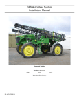
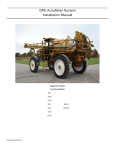
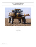
Supported Vehicles
Non-AccuGuide Ready and Non-IntelliSteer Ready
Case STX
Wheeled or Quadtrac
Case STEIGER
Wheeled or Quadtrac
New Holland TJ
New Holland T
380
380
380
9030
430
385
430
9040
480
430
480
9050
530
435
530
9060
480
485
530
535
PN: 602-0244-01-A
LEGAL DISCLAIMER
Note: Read and follow ALL instructions in this manual carefully before installing or operating the AutoSteer system.
Note: Take careful note of the safety information in the Safety Information section and throughout this manual.
The manufacturer disclaims any liability for damage or injury that results from failure to follow the instructions and warnings
set forth herein.
Please take special note of the following warnings:
1. There is NO obstacle avoidance system included in the manufacturer’s product. Therefore, users must always have an
operator on the equipment when the AutoSteer system is in use to look for any obstacles including people, animals, trees,
ditches, buildings, etc.
2. During installation of the AutoSteer system and during the Calibration and Tuning processes the vehicle's wheels turn from
side to side and the vehicle moves. Be sure that all people and obstacles are clear of the vehicle before installation, calibration and tuning, or use of the AutoSteer system.
3. Use of the AutoSteer system is NOT permitted while the vehicle is on public roads or in public areas. Ensure that the system is OFF before driving on roads or in public areas.
ii
AutoSteer System
Special Requirements
Tools
This list consists of special tools required to complete the installation. A complete set of common installation tools is assumed.
Allen Hex Key 1/8”
1/2” open wrench
13mm open wrench
Allen Key 12mm
9/16” open wrench
24mm open wrench
#2 Phillips screwdriver
5/8” open wrench
32mm open wrench
7/16” drill (11mm)
11/16” open wrench
24mm socket wrench
Portable Drill
3/4” open wrench
Oil catch pan
Hacksaw with steel cutting blade
13/16” open wrench
Cleaning rags
Ten Foot Ladder (3.5m)
7/8” open wrench
Wire cutter small
Teflon tape
15/16” open wrench
Cleaning brush
Fiberglass Cable Puller
1-1/8” open wrench
Tape measure (12ft minimum)
Hardware Installation Manual
iii
Safety Information
Warning Alerts
The AutoSteer system installer and manufacturer disclaim any responsibility for damage or physical harm caused by failure to
adhere to the following safety requirements:
•
•
As the operator of the vehicle, you are responsible for its safe operation.
The steering system is not designed to replace the vehicle’s operator.
Note: Verify all screws, bolts, nuts, hose connections, and cable connections are tight after the final installation of the
AutoSteer system.
WARNING
To avoid electrical shock hazards, remove the Roof Module
from the vehicle before driving under low structures or low
electrical power lines.
WARNING
To prevent injury from falling, ensure you are in a stable
position on the vehicle when installing or removing the Roof
Rail and Roof Module. If the vehicle does not provide a safe
platform, use a ladder to safely access the vehicle roof while
installing or removing the Roof Rail and Roof Module.
WARNING
To prevent the vehicle from running over a person, you must
never leave the vehicle while the vehicle's operator chair
with the AutoSteer engaged.
iv
AutoSteer System
WARNING
High-Pressure Fluid Hazard
Read this manual before installation. Wear hand and eye
protection while performing hydraulic system maintenance.
Relieve hydraulic system pressure before servicing the
hydraulic system.
WARNING
To understand the potential hazards associated with the
operation of AutoSteer equipment read the provided
documentation before installing the AutoSteer system on a
vehicle.
WARNING
To prevent the accidental engagement of the AutoSteer
system and loss of vehicle control while driving on roads,
shut down the AutoSteer system (exit the program). Never
drive on roads or in public areas with the AutoSteer system
turned on.
Hardware Installation Manual
v
Caution Alerts
The AutoSteer system installer and manufacturer disclaim any responsibility for damage or physical harm caused by failure to
adhere to the following safety requirements:
CAUTION
The Roof Module must be removed when transporting or
driving the vehicle at speeds above 30 mph (50 km/h). The
Roof Module can possibly detach due to wind loads at
higher speeds.
CAUTION
The AutoSteer system does not detect obstacles in the
vehicle’s path. The operator must observe the path being
driven in order to avoid obstacles.
CAUTION
When engaged, the AutoSteer controls only the steering of
the vehicle. The operator must control the speed of the
vehicle.
CAUTION
The AutoSteer must be powered OFF when installing or
removing the Roof Module.
vi
AutoSteer System
CAUTION
The Roof Module must always be firmly secured to the Roof
Rail using the provided hardware whenever the vehicle is in
operation to prevent the Roof Module from releasing from its
bracket and falling.
Vehicle Requirements
This kit is for installing the AutoSteer system on STX/TJ series tractors built in 2006 or later and not AccuGuide-ready. If your
tractor is AccuGuide-Ready, contact your dealer for the correct installation kit.
The tractor must be equipped with a fully functional Power Beyond system, including a Pressure Port and a Load Sense on the
back of the vehicle.
The vehicle steering and hydraulic systems must be in good working order before installing the AutoSteer system. Check for
loose or warn parts. Drive the vehicle and confirm that is steers straight and that the wheels can be turned from full left to full
right before installing the AutoSteer system. Check for oil leaks in the steering system and hydraulic hoses.
The vehicle’s electrical system and battery must be in good working order.
The vehicle should be fully cleaned before installing the AutoSteer system. A clean tractor will facilitate the installation, cable
routing and hose routing, and will also reduce the chance for oil contamination when the hoses are opened. Clean all the
attachment points described in this manual.
Hardware Installation Manual
vii
Important Information
Note: Verify that all screws, bolts, nuts, hose connections, and cable connections are tight after the final installation of the
AutoSteer system.
Technical Support
Refer to your Display user manual for technical support information.
Contact Information
Refer to your Display user manual for contact information.
AccuGuide, IntelliSteer and Quadtrac are registered trademarks of CNH Global N.V and its subsidiaries.
Copyright © 2009 All Rights Reserved.
viii
AutoSteer System
Table of Contents
Chapter 1
Installation Overview ....................................................................................................... 1
Vehicle Inspection . . . . . . . . . . . . . . . . . . . . . . . . . . . . . . . . . . . . . . . . . . . . . . . . . . . . . . . . . . . 1
Kit Overview . . . . . . . . . . . . . . . . . . . . . . . . . . . . . . . . . . . . . . . . . . . . . . . . . . . . . . . . . . . . . . . 2
Assemblies . . . . . . . . . . . . . . . . . . . . . . . . . . . . . . . . . . . . . . . . . . . . . . . . . . . . . . . . . . . . . . . 2
Installation Procedure Outline . . . . . . . . . . . . . . . . . . . . . . . . . . . . . . . . . . . . . . . . . . . . . . . . . . 7
Cable Diagram . . . . . . . . . . . . . . . . . . . . . . . . . . . . . . . . . . . . . . . . . . . . . . . . . . . . . . . . . . . . . . 8
Chapter 2
Steering Valve Installation .............................................................................................. 9
Steering Valve Installation Procedure Overview. . . . . . . . . . . . . . . . . . . . . . . . . . . . . . . . . . . . 9
Hose Kit . . . . . . . . . . . . . . . . . . . . . . . . . . . . . . . . . . . . . . . . . . . . . . . . . . . . . . . . . . . . . . . . . . 10
Check Valve Configuration . . . . . . . . . . . . . . . . . . . . . . . . . . . . . . . . . . . . . . . . . . . . . . . . . . . 11
Install the Steering Valve Bracket . . . . . . . . . . . . . . . . . . . . . . . . . . . . . . . . . . . . . . . . . . . . . . 13
Hydraulic Hose Connection Procedures . . . . . . . . . . . . . . . . . . . . . . . . . . . . . . . . . . . . . . . . . 15
Pressure Hose Connection . . . . . . . . . . . . . . . . . . . . . . . . . . . . . . . . . . . . . . . . . . . . . . . . . . 17
Tank Hose Connection . . . . . . . . . . . . . . . . . . . . . . . . . . . . . . . . . . . . . . . . . . . . . . . . . . . . 20
Load Sense Hose Connection . . . . . . . . . . . . . . . . . . . . . . . . . . . . . . . . . . . . . . . . . . . . . . . 21
Steering Valve Right and Left Steering Hose Connections. . . . . . . . . . . . . . . . . . . . . . . . . 24
Pressure Transducer Installation . . . . . . . . . . . . . . . . . . . . . . . . . . . . . . . . . . . . . . . . . . . . . . . 28
Steering Valve Installation Checklist. . . . . . . . . . . . . . . . . . . . . . . . . . . . . . . . . . . . . . . . . . . . 29
Chapter 3
Wheel Angle Sensor (WAS) Installation....................................................................... 31
Mounting Wheel Angle Sensor Hardware. . . . . . . . . . . . . . . . . . . . . . . . . . . . . . . . . . . . . . 33
Cutting Linkage Rods to Length . . . . . . . . . . . . . . . . . . . . . . . . . . . . . . . . . . . . . . . . . . . . . 34
Assembling Linkage Rod Hardware . . . . . . . . . . . . . . . . . . . . . . . . . . . . . . . . . . . . . . . . . . 36
Attaching and Adjusting Wheel Angle Sensor Linkage Rods. . . . . . . . . . . . . . . . . . . . . . . 39
Chapter 4
SA Module Installation .................................................................................................. 49
SA Module Mounting Orientation . . . . . . . . . . . . . . . . . . . . . . . . . . . . . . . . . . . . . . . . . . . . . . 49
Mount the SA Module . . . . . . . . . . . . . . . . . . . . . . . . . . . . . . . . . . . . . . . . . . . . . . . . . . . . . . . 50
Chapter 5
Roof Module Installation................................................................................................ 53
Safety Notes . . . . . . . . . . . . . . . . . . . . . . . . . . . . . . . . . . . . . . . . . . . . . . . . . . . . . . . . . . . . . . . 53
Roof Rail Installation . . . . . . . . . . . . . . . . . . . . . . . . . . . . . . . . . . . . . . . . . . . . . . . . . . . . . . . . 54
Chapter 6
Display Installation ......................................................................................................... 59
Introduction . . . . . . . . . . . . . . . . . . . . . . . . . . . . . . . . . . . . . . . . . . . . . . . . . . . . . . . . . . . . . . . 59
Installation Procedure . . . . . . . . . . . . . . . . . . . . . . . . . . . . . . . . . . . . . . . . . . . . . . . . . . . . . . . 60
Chapter 7
Connecting System Cables............................................................................................ 63
SA Module Harness . . . . . . . . . . . . . . . . . . . . . . . . . . . . . . . . . . . . . . . . . . . . . . . . . . . . . . . . . 63
SA Module Connection . . . . . . . . . . . . . . . . . . . . . . . . . . . . . . . . . . . . . . . . . . . . . . . . . . . . 64
Wheel Angle Sensor Connection. . . . . . . . . . . . . . . . . . . . . . . . . . . . . . . . . . . . . . . . . . . . . 67
Steering Valve Connection . . . . . . . . . . . . . . . . . . . . . . . . . . . . . . . . . . . . . . . . . . . . . . . . . 68
Main Cable Harness . . . . . . . . . . . . . . . . . . . . . . . . . . . . . . . . . . . . . . . . . . . . . . . . . . . . . . . . . 68
Roof Module . . . . . . . . . . . . . . . . . . . . . . . . . . . . . . . . . . . . . . . . . . . . . . . . . . . . . . . . . . . . 69
Main Cable Harness Connections Inside Cab . . . . . . . . . . . . . . . . . . . . . . . . . . . . . . . . . . . 73
SA Module Harness . . . . . . . . . . . . . . . . . . . . . . . . . . . . . . . . . . . . . . . . . . . . . . . . . . . . . . . 74
Power Supply Connection . . . . . . . . . . . . . . . . . . . . . . . . . . . . . . . . . . . . . . . . . . . . . . . . . . . . 74
Hardware Installation Manual
ix
Cab Power Connection . . . . . . . . . . . . . . . . . . . . . . . . . . . . . . . . . . . . . . . . . . . . . . . . . . . . 75
Battery Power Connection . . . . . . . . . . . . . . . . . . . . . . . . . . . . . . . . . . . . . . . . . . . . . . . . . . 76
Chapter 8
Post-Installation Procedures and Information ............................................................. 77
Hydraulic Leak Check . . . . . . . . . . . . . . . . . . . . . . . . . . . . . . . . . . . . . . . . . . . . . . . . . . . . . . . 77
Create New Vehicle . . . . . . . . . . . . . . . . . . . . . . . . . . . . . . . . . . . . . . . . . . . . . . . . . . . . . . . . . 78
Calibration and Tuning Guidelines . . . . . . . . . . . . . . . . . . . . . . . . . . . . . . . . . . . . . . . . . . . . . 78
Chapter 9
Final Hardware Installation Checklist ........................................................................... 79
x
AutoSteer System
1
Installation Overview
This Installation Overview chapter contains information in the following sections:
•
•
•
•
Vehicle Inspection
Kit Overview
• Assemblies
• Common Kit Components
• Hose Kit Components
• Bracket Kit Components
Installation Procedure Outline
Cable Diagram
This installation guide describes the AutoSteer system installation on several models of Case STX and Steiger wheeled and
QuadTrac, New Holland TJ and New Holland T Wheeled. The AutoSteer installation kit PN: 188-0045-01, which contains the
components shown in Figure 1-1 and detailed in Table 1-1, is used on these vehicle series. The Assemblies section of this
manual contains the sub-assembly identification information.
Vehicle Inspection
Before you install this AutoSteer system, confirm the vehicle steering system is in good working order. Drive the vehicle and
verify the vehicle’s correct working order. Also, ensure the following system operations and components:
•
•
•
•
•
•
Verify you can turn the vehicle.
Ensure the vehicle steers straight.
Check for loose or worn steering components.
Check for hydraulic fluid leaks throughout the system.
Ensure the hydraulic fluid level is correct.
Service the vehicle if the steering is not in good working order.
Hardware Installation Guide
1
Kit Overview
Kit Overview
Figure 1-1
Case and New Holland Kit Components (PN: 188-0045-01)
Table 1-1
Case and New Holland Kit Components (PN: 188-0045-01)
Item
Component
Part Number
1.
Common Kit
153-0009-01
2.
Hydraulic Hose Kit
500-0368-02
3.
Bracket Kit
152-0052-01
4.
High Flow Valve
500-0016-04
Assemblies
The Case and New Holland vehicle installation kit contains the following components:
•
2
Common Kit Components
AutoSteer System
Kit Overview
•
•
Hose Kit Components
Bracket Kit Components
Common Kit Components
Figure 1-2
Common Kit Components (PN: 153-0009-01)
Table 1-2
Common Sub-Assembly Components (PN: 153-0009-01))
Item
Component
Part Number
1.
SA Module Harness
201-0371-02
2.
Common Installation Kit
200-0497-02
3.
SA Module Bracket
200-0190-01
Hardware Installation Guide
3
Kit Overview
Item
Component
Part Number
4.
Mounting Hardware
200-0076-01
5.
Display Mounting Base Assembly
200-0508-01
7.
Warning Labels
603-0074-01
14.
SA Module Assembly
200-0206-01
Hose Kit Components
Figure 1-3
Hose Kit Components (PN: 500-0368-02)
Table 1-3
Hydraulic Kit Components (PN: 500-0368-02)
4
Item
Component
Part Number
1.
Hose Assembly 1/2” x 174”, -8F x -8F 90 DEG. ORFS
F451TC-JCJ9080808-174
2.
Hose Assembly 1/2” x 96”, -8F x -10F ORFS
F451TC-JCJC081008-96
AutoSteer System
Kit Overview
Item
Component
Part Number
3.
Hose Assembly 3/8” x 174”, -8F ORFS x -8F 90 DEG. ORFS
F451TC-JCJ9080806-174
4.
Hose Assembly 1/2” x 42”, -8F x -8M ORFS
F451TC-JCJ0080808-42
5.
Cable Tiesa
200-0467-01
6.
Hose Assembly 1/2” x 42”, -8F x -8F ORFS
F451TC-JCJC080808-42
7.
Nut Elbow Adapter
8 C6LO
8.
Straight Adapter
8M27F87OMLO
9.
Run Tee Adapter
10 R6LO-S
10.
Check Valve
DT-500-MOMS-5
11.
Adapter M18 ORB x -8M ORFS
8M18F870MLO
12.
Adapter 45 Deg. Elbow -8 ORFS
8 V6LO-S
a. The colored cable ties included in the kit are used to identify the hydraulic hoses. Place identical
colored cable ties at the ends of each hydraulic hose to positively identify the hose.
The suggested hose color assignments are as follows:
Pressure - Red
Tank - Green
LS - Grey
Steer Out Right- Yellow
Steer Out Left- Orange
Steer In Right - Yellow and Blue
Steer In Left - Orange and Blue
Hardware Installation Guide
5
Kit Overview
Bracket Kit Components
Figure 1-4
Bracket Kit Components (PN: 152-0052-01)
Table 1-4
Bracket Kit Components (PN: 152-0052-01)
6
Item
Component
Part Number
1.
Display Bracket Assembly
200-0256-02
2.
Bolt Kit
200-0451-01
3.
Installation Guide
602-0244-01
AutoSteer System
Installation Procedure Outline
Installation Procedure Outline
Note: The system interconnect cable diagram in the Cable Diagram on page 8 section of this chapter shows the AutoSteer
electrical connections.
1. Verify shipped components.
Note: Step 2, Step 3, Step 4, Step 5, Step 8, Step 9, and Step 14 are skipped if installing an electric steering actuator.
2. Install the Hydraulic Steering Valve Assembly.
3. Install the Hydraulic Hoses.
4. Install the Wheel Angle Sensor. (Optional)
5. Install the SA Module.
6. Install the Roof Rail on the cab roof.
7. Install the Roof Module on the Roof Rail.
8. Install the SA Module Harness and route cables to the various sensors.
9. Route SA Module Harness towards the cab.
10. Install the Display Bracket and the RAM Mount Ball inside the cab.
11. Install the Display using a RAM Mount.
12. Install the Main Cable Harness and route cables to Roof Module and power connector.
Note: Instructions for connecting the vehicle kit cables to the Display can be found in the Display user manual.
13. Connect the Main Cable Harness to the Display Harness.
14. Connect the Main Cable Harness to the SA Module Harness.
15. Verify all connectors are properly coupled and secured.
16. Power ON the system.
17. Calibrate the vehicle.
18. Tune the vehicle.
19. Verify the system has been installed properly and operates satisfactorily.
Hardware Installation Guide
7
Cable Diagram
Cable Diagram
8
AutoSteer System
2
Steering Valve Installation
This Steering Valve Installation chapter information is provided in the following sections:
•
•
•
•
•
•
•
Steering Valve Installation Procedure Overview
Hose Kit
Check Valve Configuration
Install the Steering Valve Bracket
Hydraulic Hose Connection Procedures
• Pressure Hose Connection
• Tank Hose Connection
• Load Sense Hose Connection
• Steering Valve Right and Left Steering Hose Connections
Pressure Transducer Installation
Steering Valve Installation Checklist
Steering Valve Installation Procedure Overview
Note: You can use a fiberglass cable puller to make it easier to pull the hydraulic hoses and electrical cables through and
around the vehicle.
1. Configure the Check Valve.
2. Install the Steering Valve on the vehicle.
3. Connect the seven hoses between the Steering Valve and the vehicle.
4. Check for oil leaks.
5. Perform a functional test to confirm correct Steering Valve operation.
WARNING
High-Pressure Fluid Hazard
Read this manual before installation. Wear hand and eye
protection while performing hydraulic system maintenance.
Relieve hydraulic system pressure before servicing the
hydraulic system.
Hardware Installation Manual
9
Hose Kit
Hose Kit
Figure 2-1
Hose Kit Components (PN: 500-0368-02)
Table 2-1
Hydraulic Kit Components (PN: 500-0368-02)
Item
Component
Part Number
1.
Hose Assembly 1/2” x 174”, -8F x -8F 90 DEG. ORFS
F451TC-JCJ9080808-174
2.
Hose Assembly 1/2” x 96”, -8F x -10F ORFS
F451TC-JCJC081008-96
3.
Hose Assembly 3/8” x 174”, -8F ORFS x -8F 90 DEG. ORFS
F451TC-JCJ9080806-174
4.
Hose Assembly 1/2” x 42”, -8F x -8M ORFS
F451TC-JCJ0080808-42
5.
Cable Tiesa
200-0467-01
6.
Hose Assembly 1/2” x 42”, -8F x -8F ORFS
F451TC-JCJC080808-42
7.
Nut Elbow Adapter
8 C6LO
10
AutoSteer System
Check Valve Configuration
Item
Component
Part Number
8.
Straight Adapter
8M27F87OMLO
9.
Run Tee Adapter
10 R6LO-S
10.
Check Valve
DT-500-MOMS-5
11.
Adapter M18 ORB x -8M ORFS
8M18F870MLO
12.
Adapter 45 Deg. Elbow -8 ORFS
8 V6LO-S
a. The colored cable ties included in the kit are used to identify the hydraulic hoses. Place identical
colored cable ties at the ends of each hydraulic hose to positively identify the hose.
The suggested hose color assignments are as follows:
Pressure - Red
Tank - Green
LS - Grey
Steer Out Right- Yellow
Steer Out Left- Orange
Steer In Right - Yellow and Blue
Steer In Left - Orange and Blue
Check Valve Configuration
1. Before installing the Steering Valve on the vehicle, you must first install a Check Valve on the Load Sense port (LS). The
Check Valve looks like a normal hose adapter, but has an internal spring. See Figure 2-2.
Figure 2-2
Check Valve
Hardware Installation Manual
11
Check Valve Configuration
2. Remove the hose adapter on the LS port and replace it with the Check Valve provided in the hose kit. See Figure 2-3.
Figure 2-3
Replace Check Valve
LS Port
12
AutoSteer System
Install the Steering Valve Bracket
Install the Steering Valve Bracket
1. Locate the mounting position for the Steering Valve on the right side of the tractor under the battery and behind a swinging
door panel. See Figure 2-4.
Note: You will have to drill three holes to mount the Steering Valve directly to the steel panel. See Figure 2-5.
Figure 2-4
Steering Valve Mounting Position
Mounting Location
Hardware Installation Manual
13
Install the Steering Valve Bracket
2. Mark the position for drilling three holes using the Steering Valve as a template (see Figure 2-5). The Steering Valve must
be orientated with the P, T, and LS ports facing down towards the ground. Allow clearance around the Steering Valve for
routing hoses.
3. Drill three 7/16” (11mm) holes using a portable drill. See Figure 2-5.
Note: Before drilling, check for hoses, cables, or other parts on the back side of the panel you will be drilling.
Figure 2-5
Drill Mounting Holes
Drill Holes
14
AutoSteer System
Hydraulic Hose Connection Procedures
Note: STX Quadtrac tractors do not provide the same size mounting surface for the valve. When installing the valve
on an STX Quadtrac tractor, mount the valve on the right mud guard inclined surface. Drill three holes as required to
secure the valve to the mudguard.
4. Mount the Steering Valve against the steel panel and secure using the three 3/8” Allen screws and locknuts provided with
the Steering Valve. See Figure 2-6.
Figure 2-6
Steering Valve Mounted
Hydraulic Hose Connection Procedures
Figure 2-7 shows the hydraulic connections. You can refer to these diagrams as you are connecting the hydraulic components.
The hydraulic hose connection procedures are contained in the following sub-sections:
•
•
•
•
Pressure Hose Connection
Tank Hose Connection
Load Sense Hose Connection
Steering Valve Right and Left Steering Hose Connections
Hardware Installation Manual
15
Hydraulic Hose Connection Procedures
Figure 2-7
16
Hydraulic Hose Connection Diagram
AutoSteer System
Hydraulic Hose Connection Procedures
Pressure Hose Connection
1. Identify the Pressure port in the Power Beyond system on the back of the tractor. Use a 12mm hex key to remove the plug
on the Pressure port (identified as P). See Figure 2-8.
Figure 2-8
Remove Pressure Port Plug
Pressure Port Plug
2. Install the metric hose adapter provided in the hose kit and tighten using a 32mm wrench. See Figure 2-9.
Figure 2-9
Install Metric Hose Adapter
Metric Hose Adapter
Hardware Installation Manual
17
Hydraulic Hose Connection Procedures
3. Connect the end of the long 1/2” hose to the adapter on the P port. Install an elbow adapter on the port as shown in
Figure 2-10 for better hose routing, then connect the Pressure hose.
Figure 2-10 Connect Long Hose to P Port
Elbow Adapter
4. Route the Pressure hose towards the Steering Valve on the front of the vehicle. See Figure 2-11.
Figure 2-11 Route Pressure Hose
Pressure Hose
18
AutoSteer System
Hydraulic Hose Connection Procedures
5. Connect the other end of the hose to the Pressure port (P) under the Steering Valve. See Figure 2-12.
Figure 2-12 Steering Valve Ports Connections
6. Check every hose individually and confirm that both ends are connected to the correct ports.
7. Refer to the hose diagram in Figure 2-7 to ensure proper connection.
8. Tighten all hose fittings and adapters.
9. Check and secure all hoses using nylon cable ties.
Note: To avoid hose damage, hoses must not drop below the vehicle frame and must not contact moving parts or hot
parts such as exhaust manifolds.
Hardware Installation Manual
19
Hydraulic Hose Connection Procedures
Tank Hose Connection
1. Identify the Tank/Return line on the tractor. It is located under the cab on the left side just next to the oil reservoir. See
Figure 2-13.
Note: This is where the Tank hose will be connected.
Figure 2-13 Identify the Tank/Return Line
Tank/Return Line
20
AutoSteer System
Hydraulic Hose Connection Procedures
2. Open the hose connection and install the large Run Tee adapter provided in your hose kit. Re-connect the vehicle hose to
the end of the Run Tee, then connect the AutoSteer Tank hose to the side of the Run Tee as shown in Figure 2-14.
Figure 2-14 Install Large Run Tee Adapter
Tank/Return Line
Run Tee Adapter
3. Route the Tank hose towards the Steering Valve and connect the other end to the Tank (T) port under the Steering Valve.
See Figure 2-12.
4. Check every hose individually and confirm that both ends are connected to the correct ports.
5. Refer to the hose diagram in Figure 2-7 to ensure proper connection.
6. Tighten all hose fittings and adapters.
7. Check and secure all hoses using nylon cable ties.
Note: To avoid hose damage, hoses must not drop below the vehicle frame and must not contact moving parts or hot
parts such as exhaust manifolds.
Load Sense Hose Connection
The AutoSteer Load Sense hose is connected to the vehicle Power Beyond system Load Sense port.
Hardware Installation Manual
21
Hydraulic Hose Connection Procedures
1. Identify the tractor Power Beyond system Load Sense port. The port is identified as LS.
Note: If the tractor is using the power beyond system for powering other hydraulic implements, you may have to
install a shuttle valve to share the single LS port. Contact your AutoSteer dealer for details.
2. Remove the existing plug or quick coupler on the LS port. See Figure 2-15.
Figure 2-15 Power Beyond Valve
Load Sense Port
3. Install an M18 hose adapter on the LS port. The adapter is provided in the hose kit. See Figure 2-16.
Figure 2-16 LS Port M18 Adapter Installed
Adapter Installed
22
AutoSteer System
Hydraulic Hose Connection Procedures
4. Install an elbow adapter on the LS hose adapter as shown in Figure 2-17.
Figure 2-17 Adapter Elbow on LS Port
LS Hose
90 Degree Elbow Adapter
5. Connect the 90 degree fitting on the end of the long 3/8” LS hose to the elbow adapter.
6. Route the LS hose towards the front of the tractor along the side of the pressure hose installed previously.
7. Route the Load Sense hose towards the Steering Valve and connect it to the Check Valve that was previously installed (see
Figure 2-3) on the Load Sense (LS) port under the AutoSteer valve. See Figure 2-12.
8. Check every hose individually and confirm that both ends are connected to the correct ports.
9. Refer to the hose diagram in Figure 2-7 to ensure proper connection.
10. Tighten all hose fittings and adapters.
11. Check and secure all hoses using nylon cable ties.
Note: To avoid hose damage, hoses must not drop below the vehicle frame and must not contact moving parts or hot
parts such as exhaust manifolds.
Hardware Installation Manual
23
Hydraulic Hose Connection Procedures
Steering Valve Right and Left Steering Hose Connections
1. Identify the Right and Left Steering hose connections on the right side of the tractor just above the steering cylinder. See
Figure 2-18.
Figure 2-18 Identify the Steering Hose Connections
24
AutoSteer System
Hydraulic Hose Connection Procedures
2. Identify the two Steering hoses coming from the front of the vehicle and connecting to the two tee adapters that branch off
to the two steering cylinders. These two hoses are the main Right and Left Steering hoses that will be disconnected from
the tee adapters to complete the Steering Valve installation. See Figure 2-19.
Note: Refer to the hose diagram to understand the required hose connections before proceeding. See Figure 2-7.
Figure 2-19 Identify Steering Hoses
Steering Hoses
3. Disconnect the hose on your right, which is the Left Steering hose. Connect this hose to a short AutoSteer extender hose
and connect the extender hose to the port labeled SL on the Steering Valve. See Figure 2-20.
Figure 2-20 Connecting Steering Hoses (SL)
SL Port
Hardware Installation Manual
25
Hydraulic Hose Connection Procedures
4. Connect an AutoSteer Steering Valve hose from the tee adapter that was just opened to the port labeled L on the Steering
Valve. This completes the installation of the two Left Steering hoses. See Figure 2-21.
Figure 2-21 Connecting Steering Hoses (L)
L Port
5. Disconnect the hose on your left, which is the Right Steering hose. Connect this hose to a short AutoSteer extender hose
and connect the extender hose to the port labeled SR on the Steering Valve. See Figure 2-22.
Figure 2-22 Connecting Steering Hoses (SR)
SR Port
26
AutoSteer System
Hydraulic Hose Connection Procedures
6. Connect an AutoSteer Steering Valve hose from the tee adapter that was just opened to the port labeled R on the Steering
Valve. This completes the installation of the two Right Steering hoses. See Figure 2-23.
Figure 2-23 Connecting Steering Hoses (R)
R Port
7. Check every hose individually and confirm that both ends are connected to the correct ports.
8. Refer to the hose diagram in Figure 2-7 to ensure proper connection.
9. Tighten all hose fittings and adapters.
10. Check and secure all hoses using nylon cable ties.
Note: To avoid hose damage, hoses must not drop below the vehicle frame and must not contact moving parts or hot
parts such as exhaust manifolds.
Hardware Installation Manual
27
Pressure Transducer Installation
Pressure Transducer Installation
1. Apply 2-3 turns of teflon tape on the NPT/ORB thread adapter. See Figure 2-24.
2. Install the NPT/ORB thread adapter on the Steering Valve. See Figure 2-24.
3. then install the Pressure Transducer on the adapter. See Figure 2-24.
Figure 2-24 Pressure Transducer Installed
Pressure Transducer
Teflon Tape
4. Connect the 3-pin connector from the Steering Valve harness to the Pressure Transducer. The connector has a latch and
must be correctly orientated. See Figure 2-25.
Figure 2-25 AutoSteer Valve Installed
28
AutoSteer System
Steering Valve Installation Checklist
Steering Valve Installation Checklist
1. Mounting screws that secure the Steering Valve are tight.
2. Pressure hose is connected to correct port on Steering Valve and Power Beyond.
3. Tank hose connected to correct port on Steering Valve and Tank/Return line.
4. Check Valve was installed on Steering Valve LS port.
5. LS hose connected to Check Valve and vehicle.
6. Right Steer hoses connected correctly at both ends.
7. Left Steer hoses connected correctly at both ends.
8. Pressure Transducer installed and tight.
9. Checked that all hose fittings are tight.
10. Checked hose routing and cable ties on all hoses.
Hardware Installation Manual
29
Steering Valve Installation Checklist
30
AutoSteer System
3
Wheel Angle Sensor (WAS) Installation
This Wheel Angle Sensor Installation chapter information is provided in the following sections:
•
•
•
•
Mounting Wheel Angle Sensor Hardware
Cutting Linkage Rods to Length
Assembling Linkage Rod Hardware
Attaching and Adjusting Wheel Angle Sensor Linkage Rods
Note: The Wheel Angle Sensor is optional equipment and is not provided with the installation kit. The Wheel Angle
Sensor installation instructions are provided for special installations, when required.
Hardware Installation Manual
31
Wheel Angle Sensor (WAS) Installation
The Wheel Angle Sensor components are shown in Figure 3-1.
Figure 3-1
Wheel Angle Sensor Components
Wheel Angle Sensor Bracket
Wheel Angle Sensor
Linkage Arms
32
AutoSteer System
Linkage Arm Bracket
Mounting Wheel Angle Sensor Hardware
Mounting Wheel Angle Sensor Hardware
1. Preassemble the Wheel Angle Sensor on the bracket before vehicle installation. See Figure 3-2.
Figure 3-2
Attaching the Wheel Angle Sensor to the Bracket
The cable connector should face away from the bracket
Do not turn the two small bolts over. They act as stops.
Hardware Installation Manual
33
Cutting Linkage Rods to Length
Cutting Linkage Rods to Length
Note: Before cutting the linkage rods, verify the Wheel Angle Sensor brackets will attach to the vehicle as shown in this
manual and they are attached the correct distance from any reference points shown. If this is not possible, do not cut the
rods until it is determined if these lengths will work for your installation. Due to possible variations in the mounting
positions, these measurements could be different. These measurements are provided as a reference only. The installer is
responsible for ensuring the rods are cut to the proper length.
1. Measure and mark the two linkage rods for cutting, according to the length shown in Table 3-1.
Note: Figure 3-3 shows the measurement points used to properly cut the linkage rods.
Table 3-1
Linkage Rod Cut Lengths
Item
Length
Rod A
5.5 inches (140 mm)
Rod B
8.5 inches (216 mm)
Figure 3-3
34
Linkage Rod Cut Length Measurement Points
AutoSteer System
Cutting Linkage Rods to Length
2. Use a hack saw to cut the linkage rod to length while it is held in a bench vise. See Figure 3-4.
Figure 3-4
Linkage Rod Cutting
Hardware Installation Manual
35
Assembling Linkage Rod Hardware
Assembling Linkage Rod Hardware
1. Attach a jam nut to the end of Rod A. See Figure 3-5.
2. Connect the eye connector to the end of the Wheel Angle Sensor rod. As shown in Figure 3-5.
Note: The threaded rods must be cut to the correct lengths before final assembly.
Figure 3-5
Rod A Assembled
Eye Connector
Jam Nut
36
AutoSteer System
Assembling Linkage Rod Hardware
3. Attach the jam nuts to each end of linkage Rod B
4. Attach the ball joints to both ends of the linkage arm as shown in Figure 3-6.
Note: The bolts for the ball joints should be facing the opposite direction as shown in Figure 3-6.
Figure 3-6
Linkage Rod Assembled
Jam Nuts
Ball Joints
Note: The linkage rod after-assembly center-to-center lengths are shown in Table 3-2. Figure 3-7 shows the
measurement points for the assembled linkage rods.
Table 3-2
Assembled Linkage Rod Length
Item
Length
Rod A
6.5" (165mm)
Rod B
10" (254mm)
Hardware Installation Manual
37
Assembling Linkage Rod Hardware
Figure 3-7
Linkage Rod Measurement Points (Assembled)
Rod A Measurement
Rod B Measurement
38
AutoSteer System
Attaching and Adjusting Wheel Angle Sensor Linkage Rods
Attaching and Adjusting Wheel Angle Sensor Linkage Rods
1. Install the short linkage arm on the Wheel Angle Sensor shaft.
2. Attach the Wheel Angle Sensor linkage rod to the Wheel Angle Sensor. See Figure 3-8.
Note: Leave the Wheel Angle Sensor mounting bolts loose so the Wheel Angle Sensor can be rotated after installation
on the vehicle.
Figure 3-8
Attaching the Linkage Arm to Wheel Angle Sensor
Wheel Angle Sensor Mounting Bolts
Hardware Installation Manual
39
Attaching and Adjusting Wheel Angle Sensor Linkage Rods
3. Ensure a flat washer is placed under the screw head when attaching the linkage rod to the Wheel Angle Sensor shaft. See
Figure 3-9.
Figure 3-9
Washer on Shaft Screw
Wheel Angle Sensor Mounting Bolt
Flat Washer
Screw Head
Wheel Angle Sensor Mounting Bolt
Nut
Note: The washer should be on the bolt head side and not the nut side of the assembly.
Note: Do not turn the steering system or drive the vehicle before the Wheel Angle Sensor has been adjusted using the
AutoSteer Calibration screens. The potentiometer can only rotate a maximum of 180 degrees and if it is rotated
beyond its mechanical stops, it will be permanently damaged.
40
AutoSteer System
Attaching and Adjusting Wheel Angle Sensor Linkage Rods
4. Attach the Wheel Angle Sensor bracket to the vehicle frame in the position shown in Figure 3-10, using the supplied
bolts, nuts and washers.
Note: Figure 3-10 shows a complete Wheel Angle Sensor installation. However, in this installation step the second
linkage rod should not be attached.
Figure 3-10 Wheel Angle Sensor Bracket Installed
Wheel Angle Sensor Bracket
5. Tighten the mounting bolts using a 9/16” socket and ratchet with a 9/16” socket.
Note: Do not attach the remaining linkage arm.
Hardware Installation Manual
41
Attaching and Adjusting Wheel Angle Sensor Linkage Rods
6. Install the linkage bracket using the supplied bolts, nuts and washers. See Figure 3-11.
7. Tighten the linkage bracket bolts using a 9/16” socket and ratchet with a 9/16” wrench.
Figure 3-11 Linkage Bracket Mounted
Mounting Bracket
8. Install the long threaded linkage on the tie rod bracket using a ball joint.
9. Tighten the ball joint to the bracket with a 1/2” and 9/16” wrench.
Note: Do not attach linkage rod to Wheel Angle Sensor rod at this time.
10. With the linkage rods disconnected, turn the steering wheel so the wheels or tracks are centered (the vehicle will travel
straight ahead when moving).
11. Temporarily attach the linkage rods.
Note: Never attach the linkage rods to Wheel Angle Sensor rod and turn the steering system manually or
automatically until the fit has been verified. The linkage rods must remain apart while the steering system is turned to
the maximum right and left positions and then temporarily attached at these positions. Failure to do this may cause the
Wheel Angle Sensor or vehicle to become damaged.
Note: After the linkage rods are assembled in the following steps, they should move freely without touching any other
parts and without overextending. Make any necessary adjustments to the linkage rods if there is an interference
problem.
42
AutoSteer System
Attaching and Adjusting Wheel Angle Sensor Linkage Rods
WARNING
Always shut down the vehicle when working around the
steering axle and checking and adjusting the Wheel Angle
Sensor rod lengths. The steering axle could move suddenly
and cause severe injury or death.
12. Rotate the Wheel Angle Sensor potentiometer on top of the mounting block so that the wire connector is parallel to the
Wheel Angle Sensor rod. See Figure 3-12.
Note: The vehicle should be parked in a straight ahead position when adjusting the potentiometer angle.
Figure 3-12 Adjusting Potentiometer Angle
Wheel Angle Sensor Connector
Wheel Angle Sensor Rod
Hardware Installation Manual
43
Attaching and Adjusting Wheel Angle Sensor Linkage Rods
13. Disconnect the linkage rods and turn the steering wheel manually to the full left position.
14. Reattach the linkage assembly and verify that the Wheel Angle Sensor will not be damaged. See Figure 3-13.
15. Adjust the rod lengths as necessary.
Figure 3-13 Full Left Wheel Angle Sensor Test
16. Disconnect the linkage rods and turn the steering wheel manually to the full right position.
17. Reattach the linkage assembly and verify that the Wheel Angle Sensor will not be damaged. See Figure 3-14.
18. Adjust the linkage rod lengths as necessary.
Figure 3-14 Full Right Wheel Angle Sensor Test
44
AutoSteer System
Attaching and Adjusting Wheel Angle Sensor Linkage Rods
19. Rotate the Wheel Angle Sensor, adjust the length of either linkage arm and/or reposition the Wheel Angle Sensor
mounting bracket on the vehicle frame (if necessary) to get the maximum Wheel Angle Sensor movement.
20. Test the remaining linkage arm for length at hard left and hard right to ensure Wheel Angle Sensor travel is not exceeded.
Note: The maximum movement is reached when the Wheel Angle Sensor rod sweeps from approximately 3/16”
(5mm) from both stop bolts when the steering system is turned to the maximum right and left positions. See
Figure 3-15.
Figure 3-15 Maximum Wheel Angle Sensor Movement (as seen from bottom)
Potentiometer Screw Stops
Full Right
Range of Movement
Full Left
Note: An Ohm meter can also be used to determine if there is enough Wheel Angle Sensor movement. Connect the
Ohm meter to pins A and B of the Wheel Angle Sensor. Measure the Ohm reading at the maximum left and right
position. After subtracting the smaller number from the larger number, there should be at least a 3.75 kilohms change.
The reading should also never go below 1.6 kilohms or higher than 6.6 kilohms as this is reaching the limits of the
potentiometer and could damage the Wheel Angle Sensor.
Hardware Installation Manual
45
Attaching and Adjusting Wheel Angle Sensor Linkage Rods
21. When all the adjustments are complete, tighten all linkage rod lock nuts and bolts and the Wheel Angle Sensor rod. See
Figure 3-16.
Note: Use a 1/2” and two 9/16” wrenches to tighten the connections.
Figure 3-16 Linkage Rod Ball Joint Bolt (different vehicle shown)
46
AutoSteer System
Attaching and Adjusting Wheel Angle Sensor Linkage Rods
22. Tighten the two screws securing the potentiometer to the Wheel Angle Sensor, after final adjustments. See Figure 3-17.
Note: Use a 1/8” hex key and a 3/8” wrench.
Figure 3-17 Potentiometer Mounting Bolts
Allen Head Bolt
Mounting Nut
Hardware Installation Manual
47
Attaching and Adjusting Wheel Angle Sensor Linkage Rods
48
AutoSteer System
4
SA Module Installation
The SA Module Installation chapter contains information in the following sections:
•
•
SA Module Mounting Orientation
Mount the SA Module
SA Module Mounting Orientation
The SA Module can also only be mounted in certain orientations. Figure 4-1 shows the correct mounting positions and
Figure 4-2 shows incorrect mounting positions.
Figure 4-1
Correct SA Module Mounting Orientations
Figure 4-2
Incorrect SA Module Mounting Orientations
Hardware Installation Manual
49
Mount the SA Module
Mount the SA Module
Due to the variety of options available on vehicles and the possible configuration differences, it may be necessary to install the
SA Module in location other than the example shown here. If an alternative location is required, choose a location where the
SA Module can be protected from damage from moving parts or crop debris and excessive moisture from weather and
cleaning equipment.
Note: The SA Module Harness must be routed in a protected position to avoid damage from the moving parts.
Note: The SA Module may be installed in other locations on the vehicle that are more protected from high crops such
as corn or cotton.
1. Find the existing hole on the right side of the tractor just above the mounting position of the Steering Valve. This hole will
be used to mount the SA Module Bracket. See Figure 4-3.
Figure 4-3
SA Module Bracket Mounting Location
SA Module Bracket Mounting Location
50
AutoSteer System
Mount the SA Module
2. Mount the SA Module Bracket to the existing hole using the hex bolt and locknut provided in your kit. See Figure 4-4.
3. Mount the SA Module onto the Bracket and secure using four Phillips screws provided. See Figure 4-4.
Figure 4-4
SA Module Mounted (shown with SA Module Harness attached)
Hardware Installation Manual
51
Mount the SA Module
52
AutoSteer System
5
Roof Module Installation
This Roof Module Installation chapter contains information in the following sections:
•
•
Safety Notes
Roof Rail Installation
Safety Notes
•
•
•
•
•
The AutoSteer system must be powered OFF when installing or removing the Roof Module.
The Roof Module must always be firmly secured to the Roof Rail using the hardware whenever the vehicle is in operation
to prevent the Roof Module from releasing from its bracket and falling.
The Roof Module must be removed when transporting the vehicle at speeds above 30 mph.
Ensure you are in a safe position on the vehicle platform when removing the Roof Module, so that you do not fall or
drop the Roof Module
Use a ladder to install the Roof Rail and Roof Module.
WARNING
To prevent injury from falling, ensure you are in a stable
position on the vehicle when installing or removing the Roof
Rail and Roof Module. If the vehicle does not provide a safe
platform, use a ladder to safely access the vehicle roof while
installing or removing the Roof Rail and Roof Module.
Hardware Installation Manual
53
Roof Rail Installation
Roof Rail Installation
1. Remove the two rear cab roof bolts using a 24mm socket and ratchet, reuse the bolts to secure the Roof Rail. See
Figure 5-1.
Note: Longer bolts and spacer washers are provided for installations where the Roof Rail needs to be raised above the
roof.
Figure 5-1
Removing Bolts for Roof Rail Installation
Mounting Bolts
54
AutoSteer System
Roof Rail Installation
2. Attach the Roof Rail using the previously removed bolts along with the extra M16 flat washer supplied in cab roof bolt kit.
See Figure 5-2.
Figure 5-2
Attaching Roof Rail with Bolts
Extra Washer
Original Washer
3. Tighten the bolts securely with a 24mm socket and ratchet.
4. Figure 5-3 shows the Roof Rail installed.
Figure 5-3
Roof Rail Installed
Roof Rail
Cab Roof
Right Side of Vehicle
Hardware Installation Manual
55
Roof Rail Installation
5. Attach the three antennas to the proper Roof Module antenna connections. See Figure 5-4.
Note: Hand tighten the connections. Do not use tools or over tighten.
Figure 5-4
Antennas Attached to the Roof Module
WiFi Antenna
Cell Phone Antenna
RTK Modem Antenna
6. Remove the Locking Pin from the Roof Rail. See Figure 5-5.
Figure 5-5
Removing the Locking Pin
Locking Pin
56
AutoSteer System
Roof Rail Installation
7. Place the Roof Module on the Roof Rail. See Figure 5-6.
Figure 5-6
Mounting Roof Module on Roof Rail
8. Test the tightness of the Roof Module from side-to-side.
9. Reinsert the Locking Pin. See Figure 5-7.
Note: The Locking Pin can be inserted from either side of the Roof Rail.
Figure 5-7
Reinserting the Locking Pin
Hardware Installation Manual
57
Roof Rail Installation
10. The Roof Module is now installed. See Figure 5-8.
Figure 5-8
58
Roof Module Installed
AutoSteer System
6
Display Installation
This Display Installation chapter contains following Display information:
•
•
Introduction
Installation Procedure
Introduction
This chapter provides the instructions for installing the RAM Mount Ball in the cab so the Display can be attached later. Refer
to your Display user manual for instructions on installing the Display.
Note: The Display components may different depending on the model vehicle and the specific Display being installed.
Hardware Installation Manual
59
Installation Procedure
Installation Procedure
1. Locate the holes on the right side cab post. See Figure 6-1.
Figure 6-1
Mounting Holes on Cab Post
Mounting Holes
2. Mount the Display Bracket to the cab frame.
Note: Use the longer bolts and spacer bushings supplied in the installation kit. Use the spacer bushing between the
bracket and the cab post.
60
AutoSteer System
Installation Procedure
3. Tighten the two bracket bolts using a socket and ratchet. See Figure 6-2.
Figure 6-2
Display Mounting Bracket Installed
Display Mounting Bracket
Hardware Installation Manual
61
Installation Procedure
4. Mount the smaller bracket to the main bracket, using the nuts and bolts supplied. Tighten the bolts using a 14mm socket
and ratchet. See Figure 6-3.
Figure 6-3
Attaching Smaller Bracket to Main Bracket
5. Attach the RAM Mount to the Display Mounting Bracket. See Figure 6-4.
Figure 6-4
Attaching RAM Mount to the Display Bracket
Note: Refer to the Display user manual for the remaining Display-specific installation instructions.
62
AutoSteer System
7
Connecting System Cables
This Connecting System Cables chapter provides information for connecting the Main Cable Harness and the SA Module
Cable Harness to various vehicle and AutoSteer components in the following sections:
•
•
•
SA Module Harness
• SA Module Connection
• Wheel Angle Sensor Connection
• Steering Valve Connection
Main Cable Harness
• Roof Module
• Main Cable Harness Connections Inside Cab
• SA Module Harness
Power Supply Connection
• Cab Power Connection
• Battery Power Connection
SA Module Harness
This SA Module Harness section contains the following sub-sections:
•
•
•
SA Module Connection
Wheel Angle Sensor Connection
Steering Valve Connection
Hardware Installation Manual
63
SA Module Connection
SA Module Connection
1. Push the SA Module Harness cable through the hole in the cab floor or cable feed through.
2. Align the SA Module Harness connector to the SA Module. See Figure 7-1.
3. Open the connector latch lever. See Figure 7-1.
Figure 7-1
Connecting SA Module Connector
SA Module
SA Module Connector
Locking Mechanism in Open Position (Latch)
64
AutoSteer System
SA Module Connection
4. Press the SA Module Harness connector onto the SA Module connector.
Note: You can damage the connectors if your force them into position. Do not force them together or use tools.
5. Press the latch lever closed until it clicks and locks the connector. See Figure 7-2.
Figure 7-2
Closing the SA Module Connector
Connector Latch
Note: If you need to disconnect the SA Module connector, you must open the latch lever before attempting to pull the
connectors apart.
Hardware Installation Manual
65
SA Module Connection
6. Close the cable connector locking mechanism as shown in Figure 7-3.
Figure 7-3
SA Module Connector (closed)
Locked position
66
AutoSteer System
Wheel Angle Sensor Connection
Wheel Angle Sensor Connection
Note: This connection to the Wheel Angle Sensor is only required when using the AutoSteer Wheel Angle Sensor.
1. Attach the WAS IN cable connector to the Wheel Angle Sensor. See Figure 7-4.
Figure 7-4
Wheel Angle Sensor Cable Connection
Wheel Angle Sensor Connector
2. Secure all cables with cable ties.
Hardware Installation Manual
67
Steering Valve Connection
Steering Valve Connection
1. Connect the Steering Valve’s 4-pin and 10-pin connectors to the SA Module Harness. See Figure 7-5.
Figure 7-5
Steering Valve Connectors
Steering Valve Connectors
2. Bundle any excess cable and secure with cable ties.
Main Cable Harness
This Main Cable Harness section contains the following sub-sections:
•
•
•
68
Roof Module
Main Cable Harness Connections Inside Cab
SA Module Harness
AutoSteer System
Roof Module
Roof Module
1. Push the Main Cable Harness down through the cab floor hole. See Figure 7-6.
Figure 7-6
Passing Main Cable Harness Through the Floor Access Hole
Floor Passthrough
2. Open the battery box door to access the underside of the cab entry point. See Figure 7-7,
Figure 7-7
Battery Box Door
Battery Box Door
Hardware Installation Manual
69
Roof Module
3. Pull the cable through the hole in floor of cab. See Figure 7-8.
Figure 7-8
Routing Cable Though Cab Floor
Cab Floor Feedthrough
4. Route the cable up the cab side. See Figure 7-9.
Figure 7-9
Route the Main Cable Harness up Cab Right Side
Main Cable Harness
5. Secure the cable to the Roof Rail using cable ties.
70
AutoSteer System
Roof Module
6. Attach the cable to the Roof Module. See Figure 7-10.
Orient the 12-pin connector so the word “TOP” on the cable connector is pointing upwards (towards the sky). Insert the
cable connector into the Roof Module. Push the connector in until it “clicks” and locks in place. To remove, grasp the
connector to compress the two side latches and pull away from the Roof Module.
Note: Do not force the connector. If the connector does not engage easily, check for the correct orientation of the
connector.
Figure 7-10 Roof Module Main Harness Connection
Hardware Installation Manual
71
Roof Module
7. Attach the LAN connector to the Roof Module. See Figure 7-11.
Orient the Ethernet cable connector with the connector under the receiver so the contacts on the cable connector are
pointing towards the back of the vehicle. (This will usually be towards your right side if you are standing on the left side of
the vehicle and looking towards the Roof Module.) Slide the cable connector into the receiver and rotate the plastic
bayonet sleeve clockwise to lock the connector. The bayonet sleeve will “click” when it fully engages and locks. To
remove the cable, rotate the bayonet sleeve counterclockwise until it “clicks” and pull the connector down or away from
the Roof Module.
Note: Do not force the connector. If the connector does not engage easily, check for the correct orientation of the
connector.
Figure 7-11 Roof Module Ethernet Connection
72
AutoSteer System
Main Cable Harness Connections Inside Cab
Main Cable Harness Connections Inside Cab
Figure 7-12 shows the Main Cable Harness connections used inside the cab. Table 7-1 shows the functions of the Main Cable
Harness cab connectors. Refer to your Display user manual for instructions on connecting the Main Cable Harness
connections shown to the correct ports and harnesses on the Display and Display cables.
Figure 7-12 Main Cable Harness Cab Connections
Table 7-1
Cab Main Cable Harness Connector Functions
Main Cable Harness Connector
Connector Function
DISPLAY ETH
Display Ethernet Port (RJ-45)
DISPLAY COMM
Display Communication Port (DB-9)
VEHICLE POWER
12 Volt Power
SAM POWER
Power for SA Module
SAM DATA
Data for SA Module
CAN IN
Not Used for This Installation
CAN OUT
Not Used for This Installation
Hardware Installation Manual
73
SA Module Harness
SA Module Harness
1. Connect the SA Module Harness to the Main Cable Harness using the 4-pin connector and 12-pin connector. See
Figure 7-13.
Figure 7-13 SA Module Harness and Main Cable Harness Connections
Power Supply Connection
The following sub-sections describe basic instructions for connecting the AutoSteer system to available vehicle power
sources:
•
•
Cab Power Connection
Battery Power Connection
Note: Refer to your Display user manual before connecting the AutoSteer system to vehicle power.
The AutoSteer Main Cable Harness must be connected to a 3-pin 12V power source. Your Display user manual provides
specific instructions for connecting power to the AutoSteer system and specifies the appropriate vehicle power source.
74
AutoSteer System
Cab Power Connection
Cab Power Connection
1. Locate the cab console right-side 12V convenience power outlet. See Figure 7-14.
2. Use this 12V accessory power connector if the Display user manual specifies connecting to power inside the cab.
Figure 7-14 Convenience Power Outlet
Convenience Plug
Hardware Installation Manual
75
Battery Power Connection
Battery Power Connection
1. Locate the vehicle battery. See Figure 7-15.
Note: You must open the battery box door to access the vehicle battery. See Figure 7-15.
2. Connect to the vehicle battery if the Display user manual specifies a direct battery connection.
Figure 7-15 Vehicle Battery Location
Battery Location
Note: A battery cable is provided with the AutoSteer system when a direct battery connection is required.
76
AutoSteer System
8
Post-Installation Procedures and Information
The Post-Installation Procedures and Information chapter provides information in the following sections:
•
•
•
Hydraulic Leak Check
Create New Vehicle
Calibration and Tuning Guidelines
Once the entire AutoSteer system, including the Display and Display harnesses, have been installed on the vehicle, the
procedures and notes provided in this chapter must be followed to complete the installation and prepare the vehicle for full
AutoSteer capabilities.
Hydraulic Leak Check
On completion of installing the entire AutoSteer system including the Roof Module and Display, the system needs to be
checked for leaks. Follow the procedure below to check for leaks.
1. Clear any bystanders away from the vehicle. If there is a hydraulic leak, they could be injured.
2. Put the vehicle into Park and/or set the parking brake to prevent the vehicle from moving.
3. Turn the vehicle over for a few seconds and if the vehicle starts, immediately shut it down.
4. Walk around the vehicle and check all the hydraulic fittings that were opened. Look for any oil leaks.
5. Once all leaks have been repaired, or if none are found, start the vehicle again and let it run at a low idle.
Note: If an oil leak is noticed during any part of this test, immediately shut down the vehicle and repair the leak.
Note: The front wheels will move when the steering wheel is turned. Make sure the vehicle will not strike anything or
anyone before continuing. If necessary, move the vehicle to an open area.
6. Take the vehicle out of Park and/or remove the parking brake. Turn the steering wheel manually to the right and left stops
two or three times to get any air out of the hoses.
7. Confirm the front wheels turn in the correct direction and the vehicle steers the same as it did before the system was
installed.
8. Put the vehicle back into Park and/or reset the parking brake. Shut down the vehicle, walk around it again, and check for
any hydraulic leaks.
Hardware Installation Guide
77
Create New Vehicle
9. Once the leaks have been repaired, or if none are found, start the vehicle again and let it run at a low idle.
10. Take the vehicle out of Park and/or remove the parking brake. Move the vehicle to an open, flat area and leave the vehicle
in Park.
11. Power up the Display and navigate to the Hydraulic Valve window from the Steering Components window.
12. Command the vehicle to turn Right and then Left a few times. The vehicle should steer in the direction it is commanded. If
the vehicle rotates in the wrong direction, the hoses were attached to the wrong ports on the AutoSteer valve and need to be
switched.
13. Power down the Display, put the vehicle back into Park and/or reset the parking brake, and shutdown the vehicle.
14. Once again check the vehicle for hydraulic leaks and repair any that are found.
Create New Vehicle
Note: Do not start the vehicle until after the Hydraulic Leak Test has been performed on the vehicle. After the vehicle has
been created, shut down the AutoSteer system prior to starting the vehicle.
Once the entire system has been installed, the operator must first create a new vehicle profile. This configures the system so
the User display can properly communicate with the various sensors and components on the vehicle. Follow the procedure
below to create a new vehicle.
1. Make sure the User display is not powered ON.
2. Start the vehicle and take it to a clear area (such as an open field) where it can be calibrated.
3. Power up the AutoSteer system.
4. Follow the instructions provided in the Display user manual to create a new vehicle.
Calibration and Tuning Guidelines
Note: For optimal steering performance, the AutoSteer system must be fully calibrated and then tuned.
78
AutoSteer System
9
Final Hardware Installation Checklist
This Final Checklist chapter contains the verifications steps necessary after the installation of the AutoSteer system.
Note: The Final Hardware Installation Checklist is on the back of this page. Fill in the checklist after the installation. You
should keep a copy of this checklist and this manual for future reference when servicing the AutoSteer system.
Machine Model: _________________________________ Year: _________ Serial #: _________________________
Customer Name: _______________________________________________________________________________
Location/Address: ______________________________________________________________________________
AutoSteer Installation Kit Part Number: ______________________________________________________________
NOTES
____________________________________________________________________________________________________
____________________________________________________________________________________________________
____________________________________________________________________________________________________
____________________________________________________________________________________________________
____________________________________________________________________________________________________
____________________________________________________________________________________________________
Name of Installer: __________________________________________
Date: ________________
Hardware Installation Manual
79
Final Hardware Installation Checklist
System Installation Checklist
1. Wheel Angle Sensor installed and all fasteners are tight. (optional)
2. Display Bracket and Display are installed and all fasteners are tight.
3. Roof Rail and Roof Module are installed and all fasteners are tight.
4. SA Module is installed and all fasteners are tight.
5. All cable ends are connected.
6. All cables are secured with cable ties.
Hydraulic Installation Checklist
1. Steering Valve is installed and all fasteners are tight.
2. All hose fittings are tight.
3. Check for oil leaks on all hydraulic connections.
4. All hoses are routed and secured with cable ties.
5. Manual steering is normal after the AutoSteer installation.
AutoSteer Performance Checklist
1. Complete AutoSteer system calibration.
2. Complete AutoSteer system tuning.
3. Check total Wheel Angle Sensor counts. (optional)
Value_______________
4. Line acquisition is good.
5. On-line steering is good.
6. Manual override (kick-out) is working.
7. Steering speed from lock-to-lock is satisfactory.
Value___________Sec.
Note: See the Post-Installation Procedures and Information chapter for additional information.
80
AutoSteer System