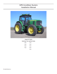
1
GPS AutoSteer System
Installation Manual
Supported Vehicles
Ag-Chem Terragator
P/N: 602-0193-01-A
6103
6203
8103
8203
9103
9203
LEGAL DISCLAIMER
Note: Read and follow ALL instructions in this manual carefully before installing or operating the AutoSteer system.
Note: Take careful note of the safety information in the Safety Information section and throughout this manual.
The manufacturer disclaims any liability for damage or injury that results from failure to follow the instructions and warnings
set forth herein.
Please take special note of the following warnings:
1. There is NO obstacle avoidance system included in the manufacturer’s product. Therefore, users must always have an
operator on the equipment when the AutoSteer system is in use to look for any obstacles including people, animals, trees,
ditches, buildings, etc.
2. During installation of the AutoSteer system and during the Calibration and Tuning processes the vehicle’s wheels turn
from side to side and the vehicle moves. Be sure that all people and obstacles are clear of the vehicle before installation,
calibration and tuning, or use of the AutoSteer system.
3. Use of the AutoSteer system is NOT permitted while the vehicle is on public roads or in public areas. Ensure that the system is OFF before driving on roads or in public areas.
ii
AutoSteer System
Special Requirements
Tools
This list consists of the tools required to complete the installation. The installer is assumed to have a complete set of common
installation tools.
Allen Hex Key 1/4”
11/16” open wrench
16mm open wrench
Allen Hex Key 3/16”
5/8” open wrench
17mm open wrench
Allen Key 5/32”
9/16” open wrench (2x)
18mm open wrench
Allen Hex Key 1/8”
1/2” open wrench
19mm open wrench
15/16” open wrench
7/16” open wrench
22mm open wrench
7/8” open wrench
1/2” 12 point ratcheting wrench
24mm open wrench
13/16” open wrench
15/16” socket wrench
18mm socket wrench
3/4” open wrench
13mm open wrench
22mm socket wrench
Breaker bar for 24mm socket
Hacksaw with steel cutting blade
24mm socket wrench
Torque wrench for 18/24/30mm
sockets
Wire cutter small
30mm socket wrench
#1 Phillips screwdriver
Cleaning brush
5000 psi Pressure Gauge with a Short
Hose and 1/8” Test Port Coupler that
meets the SAE J1502 standard.
#2 Phillips screwdriver
Ten Foot Ladder
Tape measure (12ft minimum)
Cleaning rags
Hardware Installation Manual
iii
Safety Information
Warning Alerts
The AutoSteer system installer and manufacturer disclaim any responsibility for damage or physical harm caused by failure to
adhere to the following safety requirements:
•
•
As the operator of the vehicle, you are responsible for its safe operation.
The AutoSteer system is not designed to replace the vehicle’s operator.
Note: Verify that all screws, bolts, nuts, hose connections and cable connections are tight after the final installation of the
AutoSteer system on the vehicle.
WARNING
To avoid electrical shock hazards, remove the Roof Module
from the vehicle before driving under low structures or low
electrical power lines.
WARNING
To prevent injury from falling, ensure you are in a stable
position on the vehicle when installing or removing the Roof
Rail and Roof Module. If the vehicle does not provide a safe
platform, use a ladder to safely access the vehicle roof while
installing or removing the Roof Rail and Roof Module.
WARNING
To prevent the vehicle from running over a person, you must
never leave the vehicle while the vehicle's operator chair
with the AutoSteer engaged.
iv
AutoSteer System
WARNING
High-Pressure Fluid Hazard
Read this Manual before installation. Wear hand and eye
protection while performing hydraulic system maintenance.
Relieve hydraulic system pressure before servicing the
hydraulic system.
WARNING
To understand the potential hazards associated with the
operation of AutoSteer equipment read the provided
documentation before installing the AutoSteer system on a
vehicle.
WARNING
To prevent the accidental engagement of AutoSteer and loss
of vehicle control while driving on roads, shut down the
AutoSteer system (exit the program). Never drive on roads
or in public areas with the AutoSteer system turned on.
WARNING
Do not stand close to the wheels and do not move the
machine while you are adjusting the Relief Valve. Turn off
the engine and engage the parking brake before standing
under or next to the machine.
Hardware Installation Manual
v
Caution Alerts
The AutoSteer system installer and manufacturer disclaim any responsibility for damage or physical harm caused by failure to
adhere to the following safety requirements:
CAUTION
The Roof Module must be removed when transporting or
driving the vehicle at speeds above 30 mph (50 km/h). The
Roof Module can possibly detach due to wind loads at
higher speeds.
CAUTION
The AutoSteer system does not detect obstacles in the
vehicle’s path. The operator must observe the path being
driven in order to avoid obstacles.
CAUTION
When engaged, the AutoSteer system controls only the
steering of the vehicle. The operator must control the speed
of the vehicle.
CAUTION
The AutoSteer system must be powered OFF when
installing or removing the Roof Module.
vi
AutoSteer System
CAUTION
The Roof Module must always be firmly secured to the Roof
Rail using the hardware whenever the vehicle is in operation
to prevent the Roof Module from releasing from its bracket
and falling.
Vehicle Requirements
The vehicle steering and hydraulic systems must be in good working order before installing the AutoSteer system. Check for
loose or worn parts. Before installing the AutoSteer system drive the vehicle and confirm that it steers straight and the wheels
can be turned from lock to lock. Check the steering system hydraulic hoses and connections to ensure there are no oil leaks.
The vehicle electrical system and battery must be in good working order.
The vehicle should be fully cleaned before installing the AutoSteer system. A clean vehicle will improve the overall
installation and cable routing and will also reduce the chance for oil contamination when the hydraulic connections are
opened. It is important to clean the area around the steering cylinders, frame, hydraulic pump, Orbitrol, and cab.
Hardware Installation Manual
vii
Important Information
Note: Verify that all screws, bolts, nuts, hose connections and cable connections are tight after the final installation of the
AutoSteer system on the vehicle.
Technical Support
Refer to your Display user manual for technical support information.
Contact Information
Refer to your Display user manual for contact information.
Copyright © 2009. All Rights Reserved
viii
AutoSteer System
Table of Contents
Chapter 1
Installation Overview....................................................................................... 1
Kit Overview . . . . . . . . . . . . . . . . . . . . . . . . . . . . . . . . . . . . . . . . . . . . . . . . . . . . . . . . . . . . . . . 2
Assemblies . . . . . . . . . . . . . . . . . . . . . . . . . . . . . . . . . . . . . . . . . . . . . . . . . . . . . . . . . . . . . . . 3
Installation Procedure Outline . . . . . . . . . . . . . . . . . . . . . . . . . . . . . . . . . . . . . . . . . . . . . . . . . . 8
Cable Diagram . . . . . . . . . . . . . . . . . . . . . . . . . . . . . . . . . . . . . . . . . . . . . . . . . . . . . . . . . . . . . 9
Chapter 2
Steering Valve Installation.............................................................................. 11
Steering Valve Installation Procedure Overview. . . . . . . . . . . . . . . . . . . . . . . . . . . . . . . . . . . 12
Hose Kit . . . . . . . . . . . . . . . . . . . . . . . . . . . . . . . . . . . . . . . . . . . . . . . . . . . . . . . . . . . . . . . . . . 13
Steering Valve Configuration . . . . . . . . . . . . . . . . . . . . . . . . . . . . . . . . . . . . . . . . . . . . . . . . . 15
Steering Valve Configuration . . . . . . . . . . . . . . . . . . . . . . . . . . . . . . . . . . . . . . . . . . . . . . . 16
Install the Steering Valve Bracket . . . . . . . . . . . . . . . . . . . . . . . . . . . . . . . . . . . . . . . . . . . . . . 19
Orbitrol Access . . . . . . . . . . . . . . . . . . . . . . . . . . . . . . . . . . . . . . . . . . . . . . . . . . . . . . . . . . . . 21
Hydraulic Hose Connection Procedures . . . . . . . . . . . . . . . . . . . . . . . . . . . . . . . . . . . . . . . . . 25
Tank Hose Connection . . . . . . . . . . . . . . . . . . . . . . . . . . . . . . . . . . . . . . . . . . . . . . . . . . . . 27
Pressure Hose Connection . . . . . . . . . . . . . . . . . . . . . . . . . . . . . . . . . . . . . . . . . . . . . . . . . . 29
Steering Valve Right Steering Hose Connection. . . . . . . . . . . . . . . . . . . . . . . . . . . . . . . . . 31
Steering Valve Left Steering Hose Connection. . . . . . . . . . . . . . . . . . . . . . . . . . . . . . . . . . 33
Load Sense Hose Connections. . . . . . . . . . . . . . . . . . . . . . . . . . . . . . . . . . . . . . . . . . . . . . . 35
Pressure Transducer Installation . . . . . . . . . . . . . . . . . . . . . . . . . . . . . . . . . . . . . . . . . . . . . . . 40
Adjusting the Relief Valve . . . . . . . . . . . . . . . . . . . . . . . . . . . . . . . . . . . . . . . . . . . . . . . . . . . 43
Steering Valve Installation Checklist . . . . . . . . . . . . . . . . . . . . . . . . . . . . . . . . . . . . . . . . . . . 45
Chapter 3
Wheel Angle Sensor (WAS) Installation............................................................ 47
Installing Mounting Brackets. . . . . . . . . . . . . . . . . . . . . . . . . . . . . . . . . . . . . . . . . . . . . . . . . . 48
Cut the Wheel Angle Sensor Rods to Length . . . . . . . . . . . . . . . . . . . . . . . . . . . . . . . . . . . . . 50
Assemble the Linkage Rod Hardware . . . . . . . . . . . . . . . . . . . . . . . . . . . . . . . . . . . . . . . . . . . 52
Attach the Wheel Angle Sensor Rods to Brackets and Adjust . . . . . . . . . . . . . . . . . . . . . . . . 53
Chapter 4
SA Module Installation................................................................................... 59
SA Module Mounting Orientation . . . . . . . . . . . . . . . . . . . . . . . . . . . . . . . . . . . . . . . . . . . . . . 59
Mount the SA Module . . . . . . . . . . . . . . . . . . . . . . . . . . . . . . . . . . . . . . . . . . . . . . . . . . . . . . . 60
Chapter 5
Roof Module Installation ................................................................................ 63
Safety Notes . . . . . . . . . . . . . . . . . . . . . . . . . . . . . . . . . . . . . . . . . . . . . . . . . . . . . . . . . . . . . . . 63
Roof Rail Installation . . . . . . . . . . . . . . . . . . . . . . . . . . . . . . . . . . . . . . . . . . . . . . . . . . . . . . . . 64
Chapter 6
Display Installation ........................................................................................ 69
Introduction . . . . . . . . . . . . . . . . . . . . . . . . . . . . . . . . . . . . . . . . . . . . . . . . . . . . . . . . . . . . . . . 69
Installation Procedure . . . . . . . . . . . . . . . . . . . . . . . . . . . . . . . . . . . . . . . . . . . . . . . . . . . . . . . 69
Chapter 7
Connecting System Cables............................................................................. 71
SA Module Harness . . . . . . . . . . . . . . . . . . . . . . . . . . . . . . . . . . . . . . . . . . . . . . . . . . . . . . . . . 71
SA Module Connection . . . . . . . . . . . . . . . . . . . . . . . . . . . . . . . . . . . . . . . . . . . . . . . . . . . . 72
Wheel Angle Sensor Connection. . . . . . . . . . . . . . . . . . . . . . . . . . . . . . . . . . . . . . . . . . . . . 74
Steering Valve Connection . . . . . . . . . . . . . . . . . . . . . . . . . . . . . . . . . . . . . . . . . . . . . . . . . 75
Main Cable Harness . . . . . . . . . . . . . . . . . . . . . . . . . . . . . . . . . . . . . . . . . . . . . . . . . . . . . . . . . 76
Hardware Installation Manual
ix
Roof Module . . . . . . . . . . . . . . . . . . . . . . . . . . . . . . . . . . . . . . . . . . . . . . . . . . . . . . . . . . . . 76
Main Cable Harness Connections Inside Cab . . . . . . . . . . . . . . . . . . . . . . . . . . . . . . . . . . . 79
SA Module Harness . . . . . . . . . . . . . . . . . . . . . . . . . . . . . . . . . . . . . . . . . . . . . . . . . . . . . . . 80
Power Supply Connection . . . . . . . . . . . . . . . . . . . . . . . . . . . . . . . . . . . . . . . . . . . . . . . . . . . . 81
Cab Power Connection . . . . . . . . . . . . . . . . . . . . . . . . . . . . . . . . . . . . . . . . . . . . . . . . . . . . 82
Battery Power Connection . . . . . . . . . . . . . . . . . . . . . . . . . . . . . . . . . . . . . . . . . . . . . . . . . . 83
Chapter 8
Post-Installation Procedures and Information .................................................... 85
Hydraulic Leak Check . . . . . . . . . . . . . . . . . . . . . . . . . . . . . . . . . . . . . . . . . . . . . . . . . . . . . . . 85
Create New Vehicle . . . . . . . . . . . . . . . . . . . . . . . . . . . . . . . . . . . . . . . . . . . . . . . . . . . . . . . . . 86
Calibration and Tuning Guidelines . . . . . . . . . . . . . . . . . . . . . . . . . . . . . . . . . . . . . . . . . . . . . 86
Transducer Calibration . . . . . . . . . . . . . . . . . . . . . . . . . . . . . . . . . . . . . . . . . . . . . . . . . . . . 86
Chapter 9
Final Hardware Installation Checklist ............................................................... 87
x
AutoSteer System
1
Installation Overview
This Installation Overview chapter contains information in the following sections:
•
•
•
Kit Overview
• Assemblies
• Steering Valve Kit Components
• Hose Kit Components
• Bracket Kit Components
Installation Procedure Outline
Cable Diagram
Hardware Installation Manual
1
Kit Overview
Kit Overview
The Terragator sprayers AutoSteer kit (P/N: 188-0005-01) contains the components shown in Figure 1-1.
Figure 1-1
Terragator Kit Components (P/N: 188-0005-01)
Note: Component size is not shown to scale.
Table 1-1
Terragator Kit Components (PN: 188-0005-01)
Item
Component
Part Number
1.
Steering Valve Kit
153-0001-01
2.
Hydraulic Hose Kit
500-0305-01
3.
Terragator Bracket Kit
152-0005-01
2
AutoSteer System
Kit Overview
Assemblies
The Terragator vehicle installation kit contains the following components:
•
•
•
Steering Valve Kit Components
Hose Kit Components
Bracket Kit Components
Steering Valve Kit Components
Figure 1-2
Kit Components (PN: 153-0001-01)
Hardware Installation Manual
3
Kit Overview
Table 1-2
Installation Kit Sub-Assembly Components (PN: 153-0001-01))
Item
Component
Part Number
1.
SA Module Harness
201-0371-02
2.
Common Installation Kit
200-0497-02
3.
SA Module Bracket
200-0190-01
4.
Valve Assembly
200-0457-01
5.
Valve Bracket Kit
200-0434-01
6.
Mounting Hardware
200-0076-01
7.
Display Mounting Base Assembly 200-0508-01
8.
Warning Labels
603-0074-01
15.
SA Module Assembly
200-0206-01
4
AutoSteer System
Kit Overview
Hose Kit Components
Figure 1-3
Terragator Hose Kit (PN: 500-0305-01)
Table 1-3
Terragator Hose Kit Components (PN: 500-0305-01)
Item
Component
Part Number
1.
Hose Assembly 3/8” x 84”
F451TC-JC06080606-84
2.
Hose Assembly 3/8” x 84”
F451TC-JC06060806-84
3.
Hose Assembly 1/4” x 84”
F451TC-JC06040404-84
4.
Hose Assembly 1/4” x 78”
F451TC-JC03040404-78
5.
Hose Assembly 3/8” x 84”
F451TC-JC06060606-84
6.
Hose Assembly 3/8” x 132”
F451TC-0306060606-132
7.
Hose Assembly 3/8” x 168”
F451TC-0306060606-168
Hardware Installation Manual
5
Kit Overview
Item
Component
Part Number
8.
Run Tee -6 JIC
6 R6X-S
9.
Adapter Run Tee -8 JIC
8 R6X
10.
Swivel Nut Elbow -8 JIC
8 C6X-S
11.
Adapter Reducer -8F x -6M JIC
8-6 TRTXN-S
12.
Adapter Elbow -4 JIC 37 degrees
4 C6X-S
13.
Cap -4 ORFS
4 FNL
14.
Adapter Swivel Nut Elbow -6 JIC 6 C6X-S
15.
Adapter Run Tee -4 JIC
4 R6X-S
16.
Cable Tiesa
200-0467-01
a. The colored cable ties included in the kit are used to identify
the hydraulic hoses. Place identical colored cable ties at the
ends of each hydraulic hose to positively identify the hose.
The suggested hose color assignments are as follows:
Pressure - Red
Tank - Green
LS Orbitrol - Blue
LS Out - Gray
Steer Right - Yellow
Steer Left - Orange
6
AutoSteer System
Kit Overview
Bracket Kit Components
Figure 1-4
Bracket Kit Components (PN: 152-0005-01)
Table 1-4
Bracket Kit Components (PN: 152-0005-01)
Item
Component
Part Number
1.
Roof Bolts
200-0439-01
2.
Installation Guide
602-0193-01
3.
Display Bracket
200-0440-03
4.
Power Splitter Cable
201-0024-01
Hardware Installation Manual
7
Installation Procedure Outline
Installation Procedure Outline
Note: The system interconnect cable diagram in the Cable Diagram on page 9 of this chapter shows the AutoSteer
electrical connections.
1. Verify shipped components.
Note: Step 2, Step 3, Step 4, Step 5, Step 8, Step 9, and Step 14 are skipped if installing an electric steering actuator.
2. Install the Hydraulic Steering Valve Assembly.
3. Install the Hydraulic Hoses.
4. Install the Wheel Angle Sensor. (Optional)
5. Install the SA Module.
6. Install the Roof Rail on the cab roof.
7. Install the Roof Module on the Roof Rail.
8. Install the SA Module Harness and route cables to the various sensors.
9. Route SA Module Harness towards the cab.
10. Install the Display Bracket and the RAM Mount Ball inside the cab.
11. Install the Display using a RAM Mount Arm.
12. Install the Main Cable Harness and route cables to Roof Module and power connector.
Note: Instructions for connecting the vehicle kit cables to the Display can be found in the Display owner's manual.
13. Connect the Main Cable Harness to the Display Harness.
14. Connect the Main Cable Harness to the SA Module Harness.
15. Verify all connectors are properly coupled and secured.
16. Power ON the AutoSteer system.
17. Calibrate the vehicle.
18. Tune the vehicle.
19. Verify the system has been installed properly and operates satisfactorily.
8
AutoSteer System
Installation Procedure Outline
Cable Diagram
Hardware Installation Manual
9
Installation Procedure Outline
10
AutoSteer System
2
Steering Valve Installation
This Steering Valve Installation chapter information is provided in the following sections:
•
•
•
•
•
•
•
•
•
Steering Valve Installation Procedure Overview
Hose Kit
Steering Valve Configuration
• Steering Valve Configuration
Install the Steering Valve Bracket
Orbitrol Access
Hydraulic Hose Connection Procedures
• Tank Hose Connection
• Pressure Hose Connection
• Steering Valve Right Steering Hose Connection
• Steering Valve Left Steering Hose Connection
• Load Sense Hose Connections
Pressure Transducer Installation
Adjusting the Relief Valve
Steering Valve Installation Checklist
Hardware Installation Manual
11
Steering Valve Installation Procedure Overview
Steering Valve Installation Procedure Overview
Note: You can use a fiberglass cable puller to make it easier to pull the hydraulic hoses and electrical cables through and
around the vehicle.
1. Ensure the Steering Valve plug and orifice configuration is correct before installing the Steering Valve.
Note: See the Steering Valve Configuration section for Steering Valve plug and orifice configuration information.
2. Install the Steering Valve bracket and Steering Valve on the vehicle.
3. Connect the six hoses between the Steering Valve and the vehicle steering unit (Orbitrol).
4. Check for oil leaks.
5. Adjust the Pressure Relief Valve.
6. Perform a functional test to confirm correct Steering Valve operation.
WARNING
High-Pressure Fluid Hazard
Read this manual before installation. Wear hand and eye
protection while performing hydraulic system maintenance.
Relieve hydraulic system pressure before servicing the
hydraulic system.
12
AutoSteer System
Hose Kit
Hose Kit
Figure 2-1
Terragator Hose Kit (PN: 500-0305-01)
Table 2-1
Terragator Hose Kit Components (PN: 500-0305-01)
Item
Component
Part Number
Usedb
1.
Hose Assembly 3/8” x 84”
F451TC-JC06080606-84
Yes
2.
Hose Assembly 3/8” x 84”
F451TC-JC06060806-84
Yes
3.
Hose Assembly 1/4” x 84”
F451TC-JC06040404-84
Yes
4.
Hose Assembly 1/4” x 78”
F451TC-JC03040404-78
Yes
5.
Hose Assembly 3/8” x 84”
F451TC-JC06060606-84
Yes
6.
Hose Assembly 3/8” x 132”
F451TC-0306060606-132
No
7.
Hose Assembly 3/8” x 168”
F451TC-0306060606-168
No
Hardware Installation Manual
13
Hose Kit
Item
Component
Part Number
Usedb
8.
Run Tee -6 JIC
6 R6X-S
No
9.
Adapter Run Tee -8 JIC
8 R6X
Yes
10.
Swivel Nut Elbow -8 JIC
8 C6X-S
Yes
11.
Adapter Reducer -8F x -6M JIC
8-6 TRTXN-S
Yes
12.
Adapter Elbow -4 JIC 37 degrees
4 C6X-S
Yes
13.
Cap -4 ORFS
4 FNL
No
14.
Adapter Swivel Nut Elbow -6 JIC 6 C6X-S
No
15.
Adapter Run Tee -4 JIC
4 R6X-S
No
16.
Cable Tiesa
200-0467-01
No
a. The colored cable ties included in the kit are used to identify the hydraulic
hoses. Place identical colored cable ties at the ends of each hydraulic hose
to positively identify the hose.
The suggested hose color assignments are as follows:
Pressure - Red
Tank - Green
LS Orbitrol - Blue
LS Out - Gray
Steer Right - Yellow
Steer Left - Orange
b. The Ag-Chem hose kit includes extra hoses and hose adapters for other
Ag-Chem vehicle installations. Those parts are not used on the
Terragator installation, as noted in this column.
14
AutoSteer System
Steering Valve Configuration
Steering Valve Configuration
1. Use a 3/16” Allen key to remove the four cover screws. See Figure 2-2.
2. Remove the front cover to access the hose connections, Pressure Transducer, and Relief Valve. See Figure 2-2.
Note: Figure 2-3 identifies the function of the Steering Valve assembly hydraulic connections.
Figure 2-2
Steering Valve Assembly
Figure 2-3
Steering Valve Port Identification
Note: The ports shown in Figure 2-3 are upside-down relative to the ports shown in Figure 2-2.
Hardware Installation Manual
15
Steering Valve Configuration
Table 2-2
Steering Valve Functions and Fitting Sizes
Hose Adapter
Fitting Type/Size
PRESS = PUMP PRESSURE
-8 ORFS
TANK = TANK / RETURN
-6 ORFS
LS ORBITROL = LS FROM ORBITROL
-4 ORFS
LS OUT = LS (to Priority Valve)
-4 ORFS
LEFT = LEFT STEERING CYLINDER
-6 ORFS
RIGHT = RIGHT STEERING CYLINDER
-6 ORFS
GP = DIAGNOSTICS PORT
1/8” (SAE J1502)
TRANS = PRESSURE TRANSDUCER
SAE - 4 ORB.
Steering Valve Configuration
The Steering Valve does not require any special configurations or plug and orifice changes before installing on the Terragator
series when connected directly to the steering circuit as described in this manual. The Steering Valve can be installed and
connected to the Orbitrol with the factory default plug and orifice settings. Figure 2-4 shows the correct internal plug
configurations in positions 13A, 13B, and 13C. The plug position identification are stamped on the valve block.
Note: Contact customer service before attempting other types of hydraulic installations that are not covered in this
manual.
Note: Do not install this Steering Valve on other vehicles without the appropriate installation manual. Incorrect valve
configuration and wrong hose connections on other types of steering systems can cause immediate severe pump damage.
16
AutoSteer System
Steering Valve Configuration
1. Remove the front valve cover using a 3/16” hex key to loosen the four screws.
2. Identify the three threaded plugs. See Figure 2-4.
Figure 2-4
Steering Valve With Cover Removed
13A (not shown, located on
the side of the valve)
13C
13B (shown installed)
Table 2-3
Plug and Orifice Configuration Summary
Type of Installation
13A
13B
13C
Factory Default Configuration
Plug
Open
Plug
Orbitrol Hookup Installation
Plug
Open
Plug
Hardware Installation Manual
17
Steering Valve Configuration
3. Identify the large external access plug identified in position 13B.
4. Remove the external plug in position 13B using a 1/4” hex key. See Figure 2-5.
Figure 2-5
Removing External Plug
External Plug
5. Confirm there is not an internal plug installed in position 13B.
6. If present, remove the internal plug from 13B position using a 1/8” hex key.
7. Re-install the large external plug in position 13B.
8. The Steering Valve is now ready to be installed on the vehicle.
18
AutoSteer System
Install the Steering Valve Bracket
Install the Steering Valve Bracket
1. Locate the two existing bolts under the right side of the cab. See Figure 2-6.
Figure 2-6
Bracket Bolt Location
Bracket Bolts
2. Secure the Steering Valve bracket to the sprayer frame using the two bolts. See Figure 2-7.
Figure 2-7
Steering Valve Bracket Mounted
Hardware Installation Manual
19
Install the Steering Valve Bracket
3. Secure the Steering Valve onto the bracket in the position shown using four 5/16” hex screws. See Figure 2-8.
4. Tighten the four screws using a 1/2” ratchet wrench.
Figure 2-8
Mounting Steering Valve to Bracket
Figure 2-9 shows the Steering Valve mounted on the bracket.
Figure 2-9
20
Steering Valve Mounted on the Bracket (hydraulic hoses connected)
AutoSteer System
Orbitrol Access
Orbitrol Access
1. Remove the rear engine hood to enable access to the steering unit (Orbitrol). See Figure 2-10 and Figure 2-11.
Note: The hood is secured by screws on the front and rubber straps on the back.
CAUTION
The engine hood is heavy and the removal requires at least
two people. Do not attempt to lift and move the engine
hood by yourself.
Figure 2-10 Engine Rear Hood
Hardware Installation Manual
21
Orbitrol Access
Figure 2-11 Engine Rear Hood Removed
22
AutoSteer System
Orbitrol Access
WARNING
SHOCK AND FIRE HAZARD
Avoid contact of hydraulic hose fittings with electrical
terminals located on the firewall under the engine hood.
Hydraulic hoses have a metallic braid and conduct electricity
and will cause severe shorts if they contact the electrical
terminals. See Figure 2-12.
Figure 2-12 Electrical Terminals
Electrical Terminals
Hardware Installation Manual
23
Orbitrol Access
2. Identify the ports on the Orbitrol. See Figure 2-13.
Note: Figure 2-14 shows the Orbitrol installed.
Figure 2-13 Orbitrol Port Identification
T = Tank
L = Left
P = Pressure
LS = Load Sense
R = Right
Figure 2-14 Orbitrol Under the Engine Hood
Orbitrol
24
AutoSteer System
Orbitrol Access
Hydraulic Hose Connection Procedures
Figure 2-15 and Figure 2-16 show the hydraulic connections before and after installation. You can refer to these diagrams as
you are connecting the hydraulic components. The hydraulic hose connection procedures are contained in the following
sub-sections:
•
•
•
•
•
Tank Hose Connection
Pressure Hose Connection
Steering Valve Right Steering Hose Connection
Steering Valve Left Steering Hose Connection
Load Sense Hose Connections
Figure 2-15 Hydraulic Hose Connection Diagram (Before Steering System Installation)
Hardware Installation Manual
25
Orbitrol Access
Figure 2-16 Hydraulic Hose Connection Diagram (After Steering System Installation)
26
AutoSteer System
Orbitrol Access
Tank Hose Connection
1. Remove the Tank hose (Hose 4 in Figure 2-16) from the Tank port on the Orbitrol.
2. Install a -8 JIC Run Tee on the Orbitrol Tank port. See Figure 2-17.
3. Connect the original Tank hose to the Run Tee. See Figure 2-17.
4. Connect the Tank hose (Hose 7 in Figure 2-16) from the TANK port on the Steering Valve to the Run Tee just installed on
the Orbitrol Tank port.
Note: You can install an elbow adapter on the Run Tee for better hose routing, if required.
Figure 2-17 Orbitrol Tank Port Run Tee and Hose Connected
Run Tee
Orbitrol Tank Port
Tank Hose
Hardware Installation Manual
27
Orbitrol Access
5. Connect the Tank hose (Hose 7 in Figure 2-16) to the TANK port on the Steering Valve. See Figure 2-18.
Figure 2-18 Steering Valve Tank Hose Connected
Steering Valve Tank Hose Connection
Note: The wrong hose connections on the Tank port will prevent correct LS Relief Valve operation and may damage
the pump.
6. Check every hose individually and confirm that both ends are connected to the correct ports.
7. Refer to the hose diagram in Figure 2-16 to ensure proper connection.
8. Tighten all hose fittings and adapters.
9. Check and secure all hoses using nylon cable ties.
Note: To avoid hose damage, hoses must not drop below the sprayer frame and must not contact moving parts or hot
parts such as exhaust manifolds.
28
AutoSteer System
Orbitrol Access
Pressure Hose Connection
1. Identify the Pressure port (Hose 3 in Figure 2-16) on the Orbitrol.
2. Remove the steering Pressure Hose (Hose 3 in Figure 2-16) from the Orbitrol Pressure port.
3. Install a -8 JIC Run Tee on the Orbitrol Pressure port. See Figure 2-19.
4. Reconnect the original Pressure hose to the Run Tee. See Figure 2-19.
5. Install an elbow adapter and a reducer adapter on the Run Tee side. See Figure 2-19.
6. Connect the Pressure hose (Hose 6 in Figure 2-16) to the Run Tee.
Figure 2-19 Orbitrol Pressure Port and Hose Connection
Elbow Adapter Reducer
Run Tee
Pressure Hose
Hardware Installation Manual
29
Orbitrol Access
7. Connect the Pressure hose (Hose 6 in Figure 2-16) to the PRESS port on the Steering Valve. See Figure 2-20.
Note: The Pressure port on the Steering Valve is the largest port and uses a size 8 hose adapter.
Figure 2-20 Steering Valve Pressure Hose Connection
Pressure Hose Connection
8. Check every hose individually and confirm that both ends are connected to the correct ports.
9. Refer to the hose diagram in Figure 2-16 to ensure proper connection.
10. Tighten all hose fittings and adapters.
11. Check and secure all hoses using nylon cable ties.
30
AutoSteer System
Orbitrol Access
Steering Valve Right Steering Hose Connection
1. Disconnect the Right Steer hose (Hose 1 in Figure 2-16) on the Orbitrol.
2. Install a Run Tee and reconnect the Right Steer hose to the Run Tee. See Figure 2-21.
3. Install an elbow adapter and a reducer. See Figure 2-21.
4. Connect the short Right AutoSteer hose (Hose 10 in Figure 2-16). See Figure 2-21.
Figure 2-21 Orbitrol Right Steer Connection
Elbow Adapter
Run Tee
Right Steering Port
Right Steer Hose
Hardware Installation Manual
31
Orbitrol Access
5. Connect the Right AutoSteer hose to the Steering Valve RIGHT port. See Figure 2-22.
Figure 2-22 Steering Valve Right Steer Hose Connection
Right Steer Hose Connection
6. Check every hose individually and confirm that both ends are connected to the correct ports.
7. Refer to the hose diagram in Figure 2-16 to ensure proper connection.
8. Tighten all hose fittings and adapters.
9. Check and secure all hoses using nylon cable ties.
32
AutoSteer System
Orbitrol Access
Steering Valve Left Steering Hose Connection
1. Disconnect the Left Steer hose (Hose 2 in Figure 2-16) located on the Orbitrol.
2. Install a Run Tee and reconnect the Left Steer hose to the Run Tee. See Figure 2-23.
3. Install an elbow adapter and a reducer. See Figure 2-23.
4. Connect the short Left AutoSteer hose (Hose 11 in Figure 2-16). See Figure 2-23.
Figure 2-23 Orbitrol Left Steer Connection
Elbow Adapter
Run Tee
Left Steering Port
Left Steer Hose
Hardware Installation Manual
33
Orbitrol Access
5. Connect the Left AutoSteer hose (Hose 11 in Figure 2-16) to the Steering Valve LEFT port. See Figure 2-24.
Figure 2-24 Steering Valve Left Steer Hose Connection
Left Steer Hose Connection
6. Check every hose individually and confirm that both ends are connected to the correct ports.
7. Refer to the hose diagram in Figure 2-16 to ensure proper connection.
8. Tighten all hose fittings and adapters.
9. Check and secure all hoses using nylon cable ties.
34
AutoSteer System
Orbitrol Access
Load Sense Hose Connections
1. Identify the Load Sense hose on the left side of the Orbitrol. See Figure 2-25.
Note: This Load Sense connection will be opened for installing the two AutoSteer Load Sense hoses.
Figure 2-25 Orbitrol Load Sense Port
Load Sense Port
Hardware Installation Manual
35
Orbitrol Access
2. Disconnect the original Load Sense hose (Hose 5 in Figure 2-16) from the Orbitrol. See Figure 2-26.
Note: Do not remove the existing Orbitrol Load Sense port elbow adapter.
Figure 2-26 Orbitrol Load Sense Hose Disconnected
Load Sense Hose Connection
36
AutoSteer System
Orbitrol Access
3. Connect the AutoSteer LS ORBITROL hose (hose 9) to the Load Sense port on the Orbitrol. See Figure 2-27.
Figure 2-27 Load Sense Orbitrol Hose Connection
Load Sense Hose Connected
4. Connect the other end of the LS ORBITROL hose (hose 9) to the LS ORBITROL port on the Steering Valve. See
Figure 2-28.
Figure 2-28 Steering Valve Load Sense Connection
Load Sense Connection
Hardware Installation Manual
37
Orbitrol Access
5. Connect an LS OUT hose (hose 8) to the machine’s original Load Sense hose (hose 5) that was previously disconnected
from the Orbitrol. See Figure 2-29.
Note: The LS OUT hose will have a male JIC fitting on the end that mates with the vehicle hose.
Figure 2-29 Load Sense Out to Original Load Sense Hose
38
AutoSteer System
Orbitrol Access
6. Connect the other end of the LS OUT hose (hose 8) to the LS OUT port on the Steering Valve. See Figure 2-30.
Figure 2-30 Steering Valve Load Sense Out Connection
Load Sense Out Connection
7. Check every hose individually and confirm that both ends are connected to the correct ports.
8. Refer to the hose diagram in Figure 2-16 to ensure proper connection.
9. Tighten all hose fittings and adapters.
10. Check and secure all hoses using nylon cable ties.
Hardware Installation Manual
39
Pressure Transducer Installation
Pressure Transducer Installation
1. Identify the Pressure Transducer port on the Steering Valve. It is identified as TRANS. See Figure 2-31.
2. Remove the plastic plug before installing the Pressure Transducer. See Figure 2-31.
Figure 2-31 Steering Valve Pressure Transducer Port Location
Pressure Transducer Port
3. Check if an o-ring seal is correctly installed around the top of the Pressure Transducer threads.
Note: Oil leakage will occur if an o-ring is not installed.
40
AutoSteer System
Pressure Transducer Installation
4. Install the threaded Pressure Transducer into the port identified as “TRANS.” See Figure 2-32.
5. Tighten the Pressure Transducer using a 3/4” wrench. See Figure 2-32. Do not overtighten.
Figure 2-32 Pressure Transducer Installation
Hardware Installation Manual
41
Pressure Transducer Installation
6. Connect the short transducer adapter harness to the transducer and to the 10-pin connector on the SA Module Harness. See
Figure 2-33.
7. Connect the 4-pin valve connector to the SA Module Harness connector. See Figure 2-33.
Figure 2-33 Transducer Connections
Transducer Connection
4-pin SA Module Harness Connection
10-pin SA Module Harness Connector
8. Check every hose individually and confirm that both ends are connected to the correct ports.
9. Refer to the hose diagram in Figure 2-16 to ensure proper connection.
10. Tighten all hose fittings and adapters.
11. Check and secure all hoses using nylon cable ties.
Note: To avoid hose damage, hoses must not drop below the sprayer frame and must not contact moving parts or hot
parts such as exhaust manifolds.
42
AutoSteer System
Pressure Transducer Installation
Adjusting the Relief Valve
The Steering Valve has a built-in Load Sense Relief Valve that limits the maximum pump pressure when using the AutoSteer
system. The Relief Valve must be adjusted after you have completed the hydraulic installation and before you turn on the
AutoSteer system. See Figure 2-34.
Figure 2-34 Relief Valve Adjustment
Note: When you adjust the Relief Valve, it is done with the Relief Valve mounted on the vehicle and the hydraulic hoses
connected.
Hardware Installation Manual
43
Pressure Transducer Installation
1. Install a 5000 psi pressure gauge on the valve diagnostics coupler labeled as “GP.” Use a short extension hose on the
pressure gauge if necessary for easier reading. See Figure 2-35.
Figure 2-35 Pressure Gauge
2. Put transmission into “neutral” or “park” position and turn on the hand brake.
3. Start the engine and leave it at low idle.
4. Immediately check for oil leaks on all hose connections that were opened.
5. Turn the steering wheel full right and then full left and check for correct manuals steering response. Immediately check for
oil leaks on all hose connections that were opened. Air in the hoses may cause a slight steering delay when the AutoSteer
system is first powered up.
6. Observe the standby pump pressure shown on your pressure gauge. Standby pressure should be very low or around 350
psi. If standby pump pressure is zero or less than 100 psi, you might have inverted the Pressure and Tank hoses.
7. Clear any bystanders from around the sprayer because you will be moving the front wheels in the next step.
8. Press the 100% right or left button in the Hydraulic Valve window from the Steering Components window. The front
wheels will turn quickly towards the stops. Maximum pump pressure will be indicated on the pressure gauge when the
wheels hit the stops.
9. Adjust the Relief Valve so the maximum pump pressure is 2600 psi when the wheels hit the stops.
10. Tighten the jam nut on the Relief Valve once the correct pressure setting has been adjusted.
11. Remove your pressure gauge by sliding the sleeve on the quick coupler.
Note: The objective of Load Sense Relief Valve adjustment is to establish a maximum AutoSteer pressure that is
slightly higher than the maximum pressure obtained while steering the vehicle manually.
44
AutoSteer System
Pressure Transducer Installation
Steering Valve Installation Checklist
1. Steering Valve bracket bolt is tight.
2. Mounting screws that secure the Steering Valve are tight.
3. Pressure hose is connected to correct port on Steering Valve and Orbitrol.
4. Tank hose connected to correct port on Steering Valve and Orbitrol.
5. LS-OUT hose connected to correct port on Steering Valve and the vehicle Load Sense hose.
6. LS ORBITROL hose connected to correct ports at both ends.
7. Right Steer hose connected correctly at both ends.
8. Left Steer hose connected correctly at both ends.
9. Pressure Transducer installed and tight.
10. Checked that all hose fittings are tight.
11. Checked hose routing and cable ties on all hoses. Ensure hoses are not touching moving or hot parts.
12. SA Module Harness connected to the two Steering Valve connectors.
13. 5000psi pressure gauge is installed on the Steering Valve test port.
Hardware Installation Manual
45
Pressure Transducer Installation
46
AutoSteer System
3
Wheel Angle Sensor (WAS) Installation
This Wheel Angle Sensor Installation chapter information is provided in the following sections:
•
•
•
•
Installing Mounting Brackets
Cut the Wheel Angle Sensor Rods to Length
Assemble the Linkage Rod Hardware
Attach the Wheel Angle Sensor Rods to Brackets and Adjust
Note: The Wheel Angle Sensor is optional equipment and is not provided with the installation kit. The Wheel Angle
Sensor installation instructions are provided for special installations, when required.
This Wheel Angle Sensor chapter provides the information necessary to install the Wheel Angle Sensor components.
Figure 3-1 shows the Wheel Angle Sensor assembly fully assembled.
Figure 3-1
Wheel Angle Sensor Assembled
Long Screw
Long Screw
Wheel Angle Sensor Bracket
Nylon Locknut
Linkage Rod
Bracket
Wheel Angle Sensor
Hose
Clamp
Linkage Rods
Hardware Installation Manual
47
Installing Mounting Brackets
Installing Mounting Brackets
1. The Wheel Angle Sensor bracket mounts beneath the front of the Terragator near the front wheel. Identify and open the
metal grid of the hood. Identify the existing mounting holes and insert the two longer screws provided with your kit as
shown in Figure 3-2.
Figure 3-2
Identifying the Mounting Holes and Inserting the Longer Screws
Metal Grid on Top of Hood
Left Side of Vehicle
48
AutoSteer System
Installing Mounting Brackets
2. Install the Wheel Angle Sensor bracket beneath the front of the vehicle near the front wheel.
3. Attach the Wheel Angle Sensor bracket to the two screws you have inserted previously. See Figure 3-3.
Figure 3-3
Attaching the Wheel Angle Sensor Bracket
Wheel Angle Sensor Bracket
Long Screw
4. Mount the Wheel Angle Sensor to the Wheel Angle Sensor bracket as shown in Figure 3-4.
Figure 3-4
Mounting the Wheel Angle Sensor
Wheel Angle Sensor Mounted on Bracket
Hardware Installation Manual
49
Cut the Wheel Angle Sensor Rods to Length
5. Install the Linkage Rod bracket on the power cylinder as shown in Figure 3-5.
6. Secure the Linkage Rod bracket to the right-side cylinder rod using the two hose clamps provided with your kit.
Figure 3-5
Mounting the Linkage Rod Bracket
Linkage Bracket Hose Clamps
Cut the Wheel Angle Sensor Rods to Length
The Wheel Angle Sensor rods are shipped longer than they need to be. These rods must be cut to the proper length to allow the
linkage rods to provide the Wheel Angle Sensor the maximum number of counts as the steering wheel is turned from full right
to full left. Due to the variability of the possible mounting positions and axle options, it is left to the installer to verify the
correct length for each individual installation and to cut the rods to length.
Table 3-1 provides the typical rod lengths that work for most installations. Before cutting the linkage rods to these
measurements, verify that the Wheel Angle Sensor brackets can attach to the vehicle as shown in this manual and that they are
attached the correct distance from any reference points shown. If the axle does not allow the Wheel Angle Sensor brackets to
be installed as shown, do not cut the rods until it is determined what the proper lengths are for your installation. Due to
possible variations in the mounting positions, these measurements could be different. These measurements are provided as a
reference only. The installer is responsible for verifying that the provided measurements will work prior to cutting the rods.
Use a metal hack saw and vice, as shown in Figure 3-7, to cut the Wheel Angle Sensor linkage rods to the proper lengths.
Note: It is advisable to attach a nut on the side of the metal rod that is going to be kept in order to clean the threads after
the cut has been made.
Note: Clean-up the ends of the threaded rods using a file and check if the threads are good using a steel nut: the nut
should engage smoothly on the threaded rod.
50
AutoSteer System
Cut the Wheel Angle Sensor Rods to Length
The lengths of the rods are different depending on which side of the axle it is installed on. The table shows the lengths for both
sides. Protect the threads from damage while cutting the rods. Figure 3-6 shows where the measurements provided in
Table 3-1 are measured from.
Figure 3-6
Linkage Rod Cutting and Assembly Measurement Points
Table 3-1
Linkage Rod Cut Lengths
Item
Lengtha
Rod C
6.88 inches (175mm)
Rod D
8.75 inches (223mm)
a. This measurement is the linkage rod
length prior to assembly with the ball
joints.
Hardware Installation Manual
51
Assemble the Linkage Rod Hardware
Figure 3-7
Linkage Rod Cutting
Note: The “after-assembly” center-to-center lengths of each linkage rod are shown in Table 3-2. Figure 3-6 shows the
measurement points for the assembled linkage rods.
Assemble the Linkage Rod Hardware
For most installations, use Table 3-2 to adjust the lengths of the rod assemblies to the values shown. Figure 3-6 shows where
the measurement points for each rod are taken. Due to the variation of axle types and installation points, these measurements
are provided as a reference only. Before connecting the steering rods and turning the steering axle verify that these lengths will
work and the sensor will not be damaged.
Table 3-2
Assembled Linkage Rod Length
Item
Lengtha
Rod A
7.88 inches (200mm)
Rod B
10.50 inches (267mm)
a. This measurement is the Linkage Rod length after assembly
with the ball joints.
Note: The threaded rods must be cut to the correct lengths before final assembly.
52
AutoSteer System
Assemble the Linkage Rod Hardware
Attach the Wheel Angle Sensor Rods to Brackets and Adjust
1. Loosely attach the Linkage Rods as shown in Figure 3-8.
Figure 3-8
Connecting the Linkage Rods
2. Ensure a flat washer is placed under the screw head when attaching the Linkage Rod to the sensor shaft. See Figure 3-9.
Figure 3-9
Washer on Shaft Screw
Wheel Angle Sensor Mounting Bolt
Flat Washer
Screw Head
Wheel Angle Sensor Mounting Bolt
Nut
Hardware Installation Manual
53
Assemble the Linkage Rod Hardware
Note: The washer should be on the bolt head side and not the nut side of the assembly.
3. Tighten the screw on the sensor shaft. Use a 1/8” hex key and a 3/8” wrench. See Figure 3-10.
Figure 3-10 Wheel Angle Sensor Shaft Tightening (different vehicle shown)
4. Tighten all jam nuts on the threaded rods.
WARNING
Always shut down the vehicle when working around the
steering axle and checking and adjusting the Wheel Angle
Sensor rod lengths. The steering axle could move suddenly
and cause severe injury or death.
Note: Never attach the Linkage Rods to Wheel Angle Sensor rod and turn the steering wheels manually or
automatically until the fit has been verified. The Linkage Rods must remain apart while the steering wheels are turned
to the maximum right and left positions and then temporarily attached at these positions. Failure to do this may cause
the Wheel Angle Sensor or vehicle to become damaged.
54
AutoSteer System
Assemble the Linkage Rod Hardware
Note: After the Linkage Rods are assembled in the following steps, they should move freely without touching any
other parts and without overextending. Make any necessary adjustments to the Linkage Rods if there is an interference
problem.
5. With the Linkage Rods disconnected, manually turn the steering wheel so that the wheels are centered (the vehicle will
travel straight ahead when moving).
6. Temporarily attach the Linkage Rods.
7. Rotate the Wheel Angle Sensor potentiometer on top of the mounting block so that the plastic wire connector is parallel to
the Wheel Angle Sensor rod. See Figure 3-11.
Figure 3-11 Adjust Potentiometer Angle to Match Straight Ahead
Adjust the orientation of the
Potentiometer sensor so that the
wire connector is parallel to the
Wheel Angle Sensor Rod when
wheels are straight ahead.
Vehicle Tire Direction in
Straight Ahead Position
Hardware Installation Manual
55
Assemble the Linkage Rod Hardware
8. After the potentiometer has been adjusted, tighten the potentiometer bolts with a 5/32” hex key and a 3/8” wrench. See
Figure 3-12.
Figure 3-12 Wheel Angle Sensor Potentiometer (different vehicle shown)
9. Disconnect the Linkage Rods and turn the steering wheel manually to the full left position.
10. Reattach the linkage assembly and verify that the sensor or rods will not be damaged. Adjust the rod lengths as necessary.
11. Disconnect the Linkage Rods and turn the steering wheel manually to the full right position.
12. Reattach the linkage assembly and verify that the sensor will not be damaged. Adjust the rod lengths as necessary.
13. Repeat Step 5 through Step 12 until the rod lengths have been adjusted and the potentiometer is centered to get the
maximum sensor movement. The maximum movement is reached when the Wheel Angle Sensor rod will sweep from
approximately 3/16 inch (5mm) from both bolt heads holding the potentiometer on to the block when the wheels are turned
to the maximum right and left positions. See Figure 3-13.
56
AutoSteer System
Assemble the Linkage Rod Hardware
Figure 3-13 Maximum Sensor Movement
Wheel Angle Sensor as Seen from the Bottom
Potentiometer
Screw Stop
Potentiometer
Screw Stop
Full Right
Full Left
Range of Movement
Note: An Ohm meter can also be used to determine if there is enough sensor movement. Connect the Ohm meter to
pins A and B of the Wheel Angle Sensor. Measure the Ohm reading at the maximum left and right position. After
subtracting the smaller number from the larger number, there should be at least a 3.75 kilohms change. The reading
should also never go below 1.6 or higher than 6.6 kilohms as this is reaching the limits of the potentiometer and could
damage the sensor.
Hardware Installation Manual
57
Assemble the Linkage Rod Hardware
14. Once all the adjustments are complete, tighten all lock nuts and bolts on the linkage and Wheel Angle Sensor rod. A 1/2”
and two 9/16” wrenches are required to tighten all the connections.
15. Tighten the bolt securing the two Linkage Rods together. See Figure 3-14.
Figure 3-14 Linkage Rod Ball Joint Bolt (different vehicle shown)
16. Figure 3-8 shows the completed Wheel Angle Sensor installation.
58
AutoSteer System
4
SA Module Installation
The SA Module Installation chapter contains information in the following sections:
•
•
SA Module Mounting Orientation
Mount the SA Module
SA Module Mounting Orientation
The SA Module can also only be mounted in certain orientations. Figure 4-1 shows the correct mounting positions and
Figure 4-2 shows incorrect mounting positions.
Figure 4-1
Correct SA Module Mounting Orientations
Figure 4-2
Incorrect SA Module Mounting Orientations
Hardware Installation Manual
59
Mount the SA Module
Mount the SA Module
Due to the variety of options available on vehicles and the possible configuration differences, it may be necessary to install the
SA Module in location other than the example shown here. If an alternative location is required, choose a location where the
SA Module can be protected from damage from moving parts or crop debris and excessive moisture from weather and
cleaning equipment.
Note: The SA Module Harness must be routed in a protected position to avoid damage from the moving parts.
1. Mount the SA Module Bracket in a protected position under the frame. Secure the Bracket using existing bolts on the
sprayer or the bolts and screws provided in the installation kit. See Figure 4-3.
Figure 4-3
SA Module and SA Module Bracket Overview
SA Module
Mounting Bolts
Bracket
60
AutoSteer System
Mount the SA Module
2. A complete SA Module installation is shown in Figure 4-4.
Figure 4-4
Complete SA Module Installation
SA Module Bracket
SA Module
Hardware Installation Manual
61
Mount the SA Module
62
AutoSteer System
5
Roof Module Installation
This Roof Module Installation chapter contains information in the following sections:
•
•
Safety Notes
Roof Rail Installation
Safety Notes
•
•
•
•
•
The AutoSteer system must be powered OFF when installing or removing the Roof Module.
The Roof Module must always be firmly secured to the Roof Rail using the hardware whenever the vehicle is in operation
to prevent the Roof Module from releasing from its bracket and falling.
The Roof Module must be removed when transporting the vehicle at speeds above 30 mph (50 km/h).
Ensure you are in a stable position on the sprayer platform when removing the Roof Module, so that you do not fall or drop
the Roof Module.
Use a ladder to install the Roof Rail and Roof Module.
WARNING
To prevent injury from falling, ensure you are in a stable
position on the vehicle when installing or removing the Roof
Rail and Roof Module. If the vehicle does not provide a safe
platform, use a ladder to safely access the vehicle roof while
installing or removing the Roof Rail and Roof Module.
Hardware Installation Manual
63
Roof Rail Installation
Roof Rail Installation
1. Place the ladder as close as possible to the side of the cab.
Note: A ladder is necessary to install the Roof Rail and Roof Module.
2. The Terragator sprayers have six large bolts in three pairs spread front to back. To install the Roof Rail, remove the two cab
roof bolts located at the front as shown in Figure 5-1.
Note: You may choose to install the Roof Rail on the two rear bolts if it does not interfere with the fertilizer bin or
any other attachments on the vehicle.
Figure 5-1
Existing Mounting Bolts
Vehicle’s Right
64
AutoSteer System
Roof Rail Installation
3. Center and align the Roof Rail holes to the cab roof mounting holes and fasten the Roof Rail to the roof using the two steel
bushings and longer bolts provided with your kit.
Note: The holes and the Locking Pin must be on the left side of the vehicle. See Figure 5-2.
Figure 5-2
Locking Pin and Mounting Holes on Roof Rail
Vehicle’s Right
4. Figure 5-3 shows how the steel bushings are being used to elevate the Roof Rail over the cab roof.
Figure 5-3
Using the Steel Bushings
Roof Rail
Steel Bushing
Note: The Roof Rail should be mounted so it is level when the vehicle is placed on level ground. Steering
performance will be compromised if the Roof Module is not level when the vehicle is on level ground.
Hardware Installation Manual
65
Roof Rail Installation
5. Attach the three antennas to the proper Roof Module antenna connections. See Figure 5-4.
Note: Hand tighten the connections. Do not over tighten.
Figure 5-4
Attach the Antenna
WiFi Antenna
Cell Phone Antenna
RTK Modem Antenna
6. Place the Roof Module onto the Roof Rail. The cable connector must be on the left side of the vehicle, facing the rear. See
Figure 5-5.
Figure 5-5
66
Roof Module on Roof Rail
AutoSteer System
Roof Rail Installation
7. Remove the Locking Pin from the Roof Rail. See Figure 5-6.
Figure 5-6
Removing the Locking Pin
Locking Pin
8. Adjust the Roof Module position on the Roof Rail.
9. Re-insert the Locking Pin to lock the Roof Module onto the vehicle. See Figure 5-6.
Note: The Locking Pin can be inserted from either side of the Roof Rail.
10. The completed Roof Module installation is shown in Figure 5-7.
Figure 5-7
Completed Roof Module Installation
Hardware Installation Manual
67
Roof Rail Installation
68
AutoSteer System
6
Display Installation
This Display Installation chapter contains the following information:
•
•
Introduction
Installation Procedure
Introduction
This chapter provides the instructions for installing the RAM Mount Ball in the cab so that the Display can be attached later.
Refer to your Display user manual for instructions on installing the Display.
Installation Procedure
Figure 6-1 shows the Display Bracket to be used to complete the installation of the Display in your sprayer’s cab.
Figure 6-1
Display Bracket
Note: The Display components may be different depending on the model vehicle the installation is being performed upon.
Hardware Installation Manual
69
Installation Procedure
1. Mount the Display Bracket to the steel bracket on the right side of the cab post.
2. Adjust the mounting height and tighten the two hex bolts.
3. Install the RAM Mount Base Ball (1-1/2” diameter) on the Bracket. See Figure 6-2.
Figure 6-2
Mounting the Display Bracket
Cab Post Bracket
Display Bracket
RAM Base Ball
4. Secure the RAM Base using four 10-32x3/4 Phillips screws and locknuts. Figure 6-2 shows the completed installation.
Note: Refer to the Display User Manual for the remaining Display-specific installation instructions.
70
AutoSteer System
7
Connecting System Cables
This Connecting System Cables chapter provides information for connecting the Main Cable Harness and the SA Module
Cable Harness to the various vehicle and AutoSteer components in the following sections:
•
•
•
SA Module Harness
• SA Module Connection
• Wheel Angle Sensor Connection
• Steering Valve Connection
Main Cable Harness
• Roof Module
• Main Cable Harness Connections Inside Cab
• SA Module Harness
Power Supply Connection
• Cab Power Connection
• Battery Power Connection
SA Module Harness
This SA Module Harness section contains the following sub-sections:
•
•
•
SA Module Connection
Wheel Angle Sensor Connection
Steering Valve Connection
Hardware Installation Manual
71
SA Module Harness
SA Module Connection
1. Align the SA Module Harness connector to the SA Module. See Figure 7-1.
2. Open the connector latch lever. See Figure 7-1.
Figure 7-1
Connecting SA Module Connector
SA Module
SA Module Connector
Locking Mechanism in Open Position
(Latch)
3. Press the SA Module Harness connector onto the SA Module connector.
Note: You can damage the connectors if your force them into position. Do not force them together or use tools.
72
AutoSteer System
SA Module Harness
4. Press the latch lever closed until it clicks and locks the connector. See Figure 7-2.
Figure 7-2
Closing the SA Module Connector
Note: If you need to disconnect the SA Module connector, you must open the latch lever before attempting to pull the
connectors apart.
Hardware Installation Manual
73
SA Module Harness
5. Close the cable connector locking mechanism as shown in Figure 7-3.
Figure 7-3
SA Module Connector (closed).
Locked Position
Wheel Angle Sensor Connection
Note: This connection to the Wheel Angle Sensor is only required when using the AutoSteer Wheel Angle Sensor.
1. Route the cable in a protected position and secure it with cable ties. See Figure 7-4.
Note: Route the cable along the hoses with sufficient free play to allow steering rotation of the front wheels.
74
AutoSteer System
SA Module Harness
Figure 7-4
Connecting the SA Module Cable Harness to the Wheel Angle Sensor
Wheel Angle Sensor Connector
Steering Valve Connection
1. Route and secure the steering cable from the SA Module to the Steering Valve. Connect the cable to the two valve
connectors shown in Figure 7-5.
Figure 7-5
Connecting the SA Module Cable Harness to the Steering Valve
Two Connectors
Hardware Installation Manual
75
Main Cable Harness
Main Cable Harness
This Main Cable Harness section contains the following sub-sections:
•
•
•
Roof Module
Main Cable Harness Connections Inside Cab
SA Module Harness
Roof Module
1. Route the Main Cable Harness from inside the cab to outside the cab using the existing hole. See Figure 7-6.
Figure 7-6
Routing the SA Module Cable Through the Black Panel
Note: The cable pass-through into the cab should be sealed around the cable with a non-permanent caulking material
to maintain the cab air seal integrity.
76
AutoSteer System
Main Cable Harness
2. Attach the cable to the Roof Module. See Figure 7-7.
Orient the 12-pin connector so the word “TOP” on the cable connector is pointing upwards (towards the sky). Insert the
cable connector into the Roof Module. Push the connector in until it “clicks” and locks in place. To remove, grasp the
connector to compress the two side latches and pull away from the Roof Module.
Note: Do not force the connector. If the connector does not engage easily, check for the correct orientation of the
connector.
Figure 7-7
Roof Module Main Cable Harness Connection
Hardware Installation Manual
77
Main Cable Harness
3. Attach the LAN connector to the Roof Module. See Figure 7-8.
Orient the Ethernet cable connector with the connector under the receiver so the contacts on the cable connector are
pointing towards the back of the vehicle. (This will usually be towards your right side if you are standing on the left side of
the vehicle and looking towards the Roof Module.) Slide the cable connector into the receiver and rotate the plastic
bayonet sleeve clockwise to lock the connector. The bayonet sleeve will “click” when it fully engages and locks. To
remove the cable, rotate the bayonet sleeve counterclockwise until it “clicks” and pull the connector down or away from
the Roof Module.
Note: Do not force the connector. If the connector does not engage easily, check for the correct orientation of the
connector.
Figure 7-8
78
Roof Module Ethernet Connection
AutoSteer System
Main Cable Harness
Main Cable Harness Connections Inside Cab
Figure 7-9 shows the Main Cable Harness connections used inside the cab. Table 7-1 shows the functions of the Main Cable
Harness cab connectors. Refer to your Display user manual for instructions on connecting the Main Cable Harness
connections shown to the correct ports and harnesses on the Display and Display cables.
Figure 7-9
Main Cable Harness Cab Connections
Table 7-1
Cab Main Cable Harness Connector Functions
Main Cable Harness Connector
Connector Function
DISPLAY ETH
Display Ethernet Port (RJ-45)
DISPLAY COMM
Display Communication Port (DB-9)
VEHICLE POWER
12 Volt Power
SAM POWER
Power for SA Module
SAM DATA
Data for SA Module
CAN IN
Not Used for This Installation
CAN OUT
Not Used for This Installation
Hardware Installation Manual
79
Main Cable Harness
SA Module Harness
1. Identify the gray knob on the right side of the cab. See Figure 7-10.
Figure 7-10 Identifying the Gray Knob
Gray Knob
2. Unscrew the gray knob and open the black panel.
3. Route the cable inside the cab through the hole as shown in Figure 7-11.
Note: The cable pass-through into the cab should be sealed around the cable with a non-permanent caulking material
to maintain the cab air seal integrity.
Figure 7-11 Routing the SA Module Cable Harness Through the Black Panel
80
AutoSteer System
Power Supply Connection
4. Connect the 12-pin data and 2-pin power connectors between the Main Cable Harness and the SA Module Harness. See
Figure 7-12.
Figure 7-12 Attaching the Main Cable Harness and the SA Module Harness
Power Supply Connection
The following sub-sections describe basic instructions for connecting the AutoSteer system to available vehicle power
sources:
•
•
Cab Power Connection
Battery Power Connection
Note: Refer to your Display user manual before connecting the AutoSteer system to vehicle power.
The AutoSteer Main Cable Harness must be connected to a 3-pin 12V power source. Your Display user manual provides
specific instructions for connecting power to the AutoSteer system and specifies the appropriate vehicle power source.
Hardware Installation Manual
81
Power Supply Connection
Cab Power Connection
1. Locate the cab console right-side 12V power outlet. See Figure 7-13.
2. Use this 12V accessory power connector if the Display user manual specifies connecting to power inside the cab.
Note: This power cable installation is for vehicles in the United States. European installations require the power cable
adapter P/N: 201-0234-01.
Figure 7-13 Power Outlet Inside Cab
Note: A power cable adapter is provided with your kit. When required, use this to connect two systems to a single
power outlet.
82
AutoSteer System
Power Supply Connection
Battery Power Connection
1. Locate the vehicle battery. See Figure 7-14.
2. Connect to the vehicle battery if the Display user manual specifies a direct battery connection.
Figure 7-14 Battery Location
Note: A battery cable is provided with the AutoSteer system when a direct battery connection is required.
Hardware Installation Manual
83
Power Supply Connection
84
AutoSteer System
8
Post-Installation Procedures and Information
The Post-Installation Procedures and Information chapter provides information in the following sections:
•
•
•
Hydraulic Leak Check
Create New Vehicle
Calibration and Tuning Guidelines
• Transducer Calibration
Once the entire AutoSteer system, including the Display and display harnesses, have been installed on the vehicle, the
procedures and notes provided in this chapter must be followed to complete the installation and prepare the vehicle for full
AutoSteer capabilities.
Hydraulic Leak Check
On completion of installing the entire AutoSteer system including the Roof Module and Display, the system needs to be
checked for leaks. Follow the procedure below to check for leaks.
1. Clear any bystanders away from the vehicle. If there is a hydraulic leak, they could be injured.
2. Put the vehicle into Park and/or set the parking brake to prevent the vehicle from moving.
3. Turn the vehicle over for a few seconds and if the vehicle starts, immediately shut it down.
4. Walk around the vehicle and check all the hydraulic fittings that were opened. Look for any oil leaks.
5. Once all leaks have been repaired, or if none are found, start the vehicle again and let it run at a low idle.
Note: If an oil leak is noticed during any part of this test, immediately shut down the vehicle and repair the leak.
6. Take the vehicle out of Park and/or remove the parking brake. Turn the steering wheel manually to the right and left stops
two or three times to get any air out of the hoses.
7. Confirm the vehicle steers in the correct direction and that the vehicle steers the same as it did before the system was
installed.
8. Put the vehicle back into Park and/or reset the parking brake. Shut down the vehicle, walk around it again, and check for
any hydraulic leaks.
9. Once the leaks have been repaired, or if none are found, start the vehicle again and let it run at a low idle.
10. Take the vehicle out of Park and/or remove the parking brake. Move the vehicle to an open, flat area and leave the vehicle
in Park.
11. Power up the Display.
Hardware Installation Manual
85
Create New Vehicle
12. Power up the Display and navigate to the Hydraulic Valve window from the Steering Components window.
13. Command the vehicle to turn Right and then Left a few times. The vehicle should rotate in the direction it is commanded.
If the vehicle rotates in the wrong direction, the hoses were attached to the wrong ports on the AutoSteer valve and need to
be switched.
14. Power down the Display, put the vehicle back into Park and/or reset the parking brake, and shutdown the vehicle.
15. Once again check the vehicle for hydraulic leaks and repair any that are found.
Create New Vehicle
Note: Do not start the vehicle until after the Hydraulic Leak Test has been performed on the vehicle. After the vehicle has
been created, shut down the AutoSteer system prior to starting the vehicle.
Once the entire system has been installed, the operator must first create a new vehicle profile. This configures the system so
the User display can properly communicate with the various sensors and components on the vehicle. Follow the procedure
below to create a new vehicle.
1. Make sure the User display is not powered ON.
2. Start the vehicle and take it to a clear area (such as an open field) where it can be calibrated.
3. Power up the AutoSteer system.
4. Follow the instructions provided in the Display’s user manual to create a new vehicle.
Calibration and Tuning Guidelines
Note: For optimal steering performance, the AutoSteer system must be fully calibrated and then tuned.
Transducer Calibration
The transducer calibration procedure on this vehicle is different than other AutoSteer installations because the transducer is
measuring a low pressure Load Sense pressure signal. In order to provide good manual kick-out response, you must calibrate
the pressure transducer HIGH number to be about 3000 counts above the LOW number.
Confirm that the pressure transducer calibration is correct by testing the manual kick-out feature while driving in AutoSteer
mode. AutoSteer should disengage when you turn the steering wheel. If spontaneous kick-out occurs while in AutoSteer mode,
recalibrate the pressure transducer and increase the HIGH value slightly. Repeat this procedure until you obtain good manual
kick-out without spontaneous kick-out in AutoSteer mode.
86
AutoSteer System
9
Final Hardware Installation Checklist
This Final Checklist chapter contains the verifications steps necessary after the installation of the AutoSteer system.
Note: The Final Hardware Installation Checklist is on the back of this page. Tear this page out of your manual and fill in
the checklist after the installation. You should keep a copy of this checklist for future reference when servicing the
vehicle.
Machine Model: _________________________________ Year: _________ Serial #: _________________________
Customer Name: _______________________________________________________________________________
Location/Address: ______________________________________________________________________________
AutoSteer Installation Kit Part Number: ______________________________________________________________
NOTES
____________________________________________________________________________________________________
____________________________________________________________________________________________________
____________________________________________________________________________________________________
____________________________________________________________________________________________________
____________________________________________________________________________________________________
____________________________________________________________________________________________________
Name of Installer: __________________________________________
Date: ________________
Hardware Installation Manual
87
Final Hardware Installation Checklist
System Installation Checklist
1. Wheel Angle Sensor is installed and all fasteners are tight. (optional)
2. Display Bracket and Display are installed and all fasteners are tight.
3. Roof Rail and Roof Module are installed and all fasteners are tight.
4. SA Module is installed and all fasteners are tight.
5. All cable ends are connected.
6. All cables are secured with cable ties.
Hydraulic Installation Checklist
1. Steering Valve Bracket is installed and all fasteners are tight.
2. Steering Valve is installed and all fasteners are tight.
3. All hose fittings are tight.
4. Check for oil leaks on all hydraulic connections.
5. All hoses are routed and secured with cable ties.
6. Manual steering is normal after the AutoSteer installation.
7. Relief Valve is adjusted.
AutoSteer Performance Checklist
1. Complete AutoSteer system calibration.
2. Complete AutoSteer system tuning.
3. Check total Wheel Angle Sensor counts. (optional)
Value_______________
4. Line acquisition is satisfactory.
5. On-line steering is satisfactory.
6. Manual override (kick-out) is working.
7. Steering speed from lock-to-lock is satisfactory.
Value___________Sec.
Note: See the Post-Installation Procedures and Information chapter for additional information.
88
AutoSteer System