1
E4000 air quality probe Installation manual
Ver
V1
V9
V10
V11
V12
V13
Date
Initial
Sep 2012
Nov 2012
Dec. 2012
May 2013
Oct 2013
www.nano-sense.com
Modification / Update
Version Initial/Initial version
Initial mass prod version
Air proof wiring
Temperature sensor position
LED option + High performance Positioning
Complementary KNX power supply
All Rights Reserved
Tel : 33 (0)1 41 41 00 02
page 1/22
Guide d’Installation sonde E4000
E4000 probe Installation Guide
Summary
1.
2.
3.
4.
5.
5.1.
5.2.
5.2.1.
5.2.2.
5.3.
5.4.
5.5.
5.6.
6.
6.1.
6.1.1.
6.1.2.
7.
7.1.
7.1.1.
7.1.2.
7.1.2.1.
7.1.2.2.
7.2.
7.2.1.
7.2.2.
7.2.3.
7.2.4.
7.2.4.1.
7.2.4.2.
7.2.4.3.
7.2.4.4.
8.
8.1.
8.2.
9.
10.
10.1.
10.2.
11.
Security
Positioning
Installation
Wiring
Motherboard preparation
RS485
Optional Bus board
Install the daughter board
Mount the BUS connector
Analog Option
LED Option
EnOcean Option
Gateway EnOcean-KNX Option
Install the motherboard into the case
Temperature sensor
Standard positioning
High performance positioning
Connecting
Power Supply
Power Supply Characteristics
Power supply connection
RS485, Analogical, EnOcean, KNX and LON
POE Bus
Connecting to ventilation and other elements
RS485
Analog Option
KNX or LON Sensor Mode
EnOcean sensor mode option
Pairing
Telegram Transmission Principle
Description Radio Telegram
Transmission Range
Insert gas sensors
Sensors on miniSD card
CO2 NDIR Sensor
Powering
Configuration (EnOcean, Modbus RS485 and Analogical Board)
Position the micro switches
Connection diagram according to position of micro switches
Completion of installation
3
3
4
4
4
4
5
5
5
5
5
6
6
6
7
7
7
7
7
7
8
8
9
9
9
9
9
9
10
10
10
11
12
12
13
13
15
15
16
16
ANNEXES
1.
1.1
1.2
1.3
1.4
2.
2.1.
2.1.1.
2.2.
2.3.
2.4.
3.
4.
17
Installation of BUS connections
RS485
Programming the physical address
Choice between RTU and ASCII
RS485Annexes probes
Choosing Cable Bus
RS485
Topology
KONNEX
LONWORKS
POE
Ventilation Control
Specification
17
17
18
18
18
19
19
19
19
19
20
20
21
DRILLING
www.nano-sense.com
22
All Rights Reserved
Tel : 33 (0)1 41 41 00 02
page 2/22
Guide d’Installation sonde E4000
E4000 probe Installation Guide
1. Security
WARNING
Danger of death, risk of electric shock and fire!
The installation should only be undertaken by a qualified electrician!
To apply for correct bus and power cables and to activate the device, comply with the state of the art
and standards.
Any intervention or modification to the device will invalidate any warranty claim.
• Do not use this probe in environments with regular exposure to chlorine fumes (hospitals, swimming
pools ..!) because this gas gradually alters the sensitivity of the CO2 solid state sensor. Use the NDIR
sensor in such environment.
• Do not use the sensors for measuring gas content relating to safety!
• Use the probe only with secured low voltages!
• Use an external 24VAC or DC power supply capable of delivering 60mA per probe and ensuring a
peak voltage under 40V or use the KNX bus power supply considering 50mA per probe.
2. Positioning
The position of the probe is crucial vis-à-vis efficiency and energy savings for
ventilation, heating and cooling.
• The probe is designed to ensure air quality; it must be placed in the area of
occupancy of the premise served by outlet vents, on a wall at eyes level
(breathing human level, between 1.5 and 1.8m).
• Avoid drafts (near openings, blowing air, doors, outlet vents) and dead zones
(niche, shelves and curtains).
• Avoid orthogonal walls (corners of room in particular)
• Avoid heat sources and the proximity of occupants (radius of 1 m from
workstation).
• Avoid direct exposure to sunlight.
• Position the sensor vertically on a wall or partition.
This device is not intended for installation in duct or ceilings.
• When used with an EnOcean radio module, see the complementary positioning constraints § 7.2.4.4 Transmission Range, Page 11
Any work not in accordance with this documentation or
changes to the device will invalidate all warranty claims.
www.nano-sense.com
All Rights Reserved
Tel : 33 (0)1 41 41 00 02
page 3/22
Guide d’Installation sonde E4000
E4000 probe Installation Guide
3. Installation
Attach to the wall through two holes in the case.
TOP
Take care of case orientation (TOP –BOTTOM)
ONLY use screws with bent heads
Maximum height of the head 2 mm.
BOTTOM
Make sure to position the hole of cables
path at the case bottom
4. Wiring
Be careful, wiring must be sealed. Incoming air, even slight, would seriously jam the temperature,
humidity and air quality measures.
When the switchboard is located in the heated volume: caulk arrivals between cables and ducts at the
switchboard level.
When the switchboard is out of the heated volume, caulk between cables and ducts before entering the
heated volume. A sealing plug must also be placed between duct and cable reaching the E4000 probe to
prevent air entry.
When the sealing of the duct is not possible, use a specific sealant without silicone and VOC.
In case of use of electrical box, select an airtight case with sealing membrane from
which the duct passes through. If the case crosses through the sealing plane
(plasterboard), seal between the casing and panel with a special sealant without
silicone and VOC.
5. Motherboard preparation
5.1.
RS485
The RS485 interface is resident on the motherboard
RS485 Modbus
www.nano-sense.com
All Rights Reserved
Tel : 33 (0)1 41 41 00 02
page 4/22
Guide d’Installation sonde E4000
5.2.
E4000 probe Installation Guide
Optional Bus board
5.2.1.
Install the daughter board
KNX board
LON board
POE board
Insert the Bus board into the motherboard of the
probe. Check that there is no shift in the
connectors.
5.2.2.
Mount the BUS connector
BUS plug
Motherboard with KNX
5.3.
Analog Option
5.4.
LED Option
www.nano-sense.com
Ethernet plug
Motherboard with LON
All Rights Reserved
Motherboard with POE
Tel : 33 (0)1 41 41 00 02
page 5/22
Guide d’Installation sonde E4000
5.5.
E4000 probe Installation Guide
EnOcean Option
EnOcean radio
Antenna
module
For good receiver performance, great care must be taken about the space immediately surrounding the
antenna since this has a strong influence on screening and detuning the antenna. The antenna should be
drawn out as far as possible and must never be cut off. Mainly the far end of the wire should be
mounted as far away as possible (at least 15 mm) from all metal parts, ground planes, PCB strip lines
and fast logic components (e.g. microprocessors). Do not roll up or twist the whip antenna!
5.6.
Gateway EnOcean-KNX Option
EnOcean
module
KNX
module
Note: Gas sensors must be installed after the connections and before power on.
6. Install the motherboard into the case
Clip the mother board into the case
The arrow on the board
indicates the top position
Case
www.nano-sense.com
All Rights Reserved
Tel : 33 (0)1 41 41 00 02
page 6/22
Guide d’Installation sonde E4000
6.1.
6.1.1.
E4000 probe Installation Guide
Temperature sensor
Standard positioning
The temperature sensor is located on the lowest part of the board.
This sensor is located at the end of a coiled pigtail 3cm long conductor to
minimize thermal bridging with the board and thus reduce the thermal
inertia. In addition the metal used is constantan. This alloy is a good
electrical conductor and a good thermal insulator which further reduces
the thermal the thermal bridge with the board. So in case of sudden
temperature change (window opening), the probe reacted very quickly.
For an accurate measurement, it is necessary that the sensor (the little
black ball) be in the air stream.
Pull lightly on the sensor to make it exceed by 3 mm from the dished
shape recess in the plastic housing. Do not overpass 6mm to avoid
touching the plastic cover.
Temperature sensor
A gentle stream of air is generated by the heating of the CO2 and VOCs
sensors located in the upper part. The incoming air is immediately
measured by the temperature sensor.
6.1.2. High performance positioning
The here under optimum positioning of the temperature sensor eliminates thermal phenomena in the
containment housing and improves accuracy.
Stretch the twisted cable of the sensor in
pulling it down. Put the cover from the
bottom by inserting the sensor into the
vent.
Check visually and make sure not to
exceed the border for aesthetic reasons.
7. Connecting
7.1.
7.1.1.
Power Supply
Power Supply Characteristics
Use a power supply between 12 and 24V AC or 15 and 33V DC with a fluctuation of max
value of less than 10%, preferably a DIN rail regulated one.
Make sure the voltage does not overpass 24V AC or 33V DC before connecting to the
E4000 probe.
Take into account the voltage drop in cable to assess the consumption of each sensor.
In RS485 version add 13mA to the calculated consumption. Probes are queried one after the other.
www.nano-sense.com
All Rights Reserved
Tel : 33 (0)1 41 41 00 02
page 7/22
Guide d’Installation sonde E4000
E4000 probe Installation Guide
In KNX version, the bus powers only the interface board, the main board is powered
by the secondary 31V–DC power supply (yellow and white).
Use a certified KNX power supply.
Most of KNX power supplies have a secondary 31V-DC power supply (yellow and
white cables and connector of the same colors).
In LON version use a 24V power supply independent from the bus.
In POE version, consumption is about 30mA.
Installation sample
RS485
KNX
LON
POE
Per Unit consumption
20 probes connected
45 mA
20* (45 + 13) mA
To be adjusted for
voltage losses in long
cables worn.
40 mA
20*40 = 800 mA
Δ Security : 20 % =
160 mA
Power supply :1 A
40 mA
20*40 = 800 mA
Δ Security: 20 % = 160
mA
Power supply : 1 A
30 mA
20*30 = 600 mA
Δ Security: 20 % = 120
mA
Total 720 mA
7.1.2.
Power supply connection
In all cases but POE, the probe requires a power supply separated from the bus
7.1.2.1.
RS485, Analogical, EnOcean, KNX and LON
Power supply connector
24VAC or 33V DC
RS485
EnOcean
Analog
The power supply connector is designed for monofilament cables from 0,6 to 0,8 mm of Ø. Reveal the wire on 5 mm.
It is not necessary to respect the polarity.
The KNX or LON power supply cable allows receiving and sending data and powering the interface
board only. The main board shall be powered separately
24V AC or 15+ 33V DC
Complementary Power supply REQUIRED
LON
KNX
EnOcean/KNX Gateway
For cable selection, refer to § Choice of cables attached in the annex.
www.nano-sense.com
All Rights Reserved
Tel : 33 (0)1 41 41 00 02
page 8/22
Guide d’Installation sonde E4000
E4000 probe Installation Guide
Note: KNX EnOcean Gateway
Connecting the EnOcean module enables the gateway function between KNX and EnOcean.
In addition to the gateway function, this module is used to enrich the functions between the EnOcean
sensors and EnOcean actuators by KNX settings. The pairing between the gateway and EnOcean
devices requires prior setting of KNX communication object via ETS. The pairing is then made through
the buttons of the LCD tool panel.
For detailed on settings, refer to the KNX manual setting.
Without wire bus interface board, the probe becomes an EnOcean sensor.
7.1.2.2.
POE Bus
Connect the Ethernet cable to the POE module.
The Ethernet cable provides power.
7.2.
Connecting to ventilation and other elements
7.2.1.
RS485
Measures and orders are transmitted via the RS485 Modbus.
The cable must be twisted. For the selection of cable refer to
§Choosing Cable Bus page 19.
For more details on the connection, see annex § Installation of BUS
connections page 17
+
N
7.2.2.
Analog Option
HVAC one speed
HVAC 1-2 Bridge outputs
(see 9.2)
HVAC 1-2
Logic NC
Logic NO
HVAC two speeds
HVAC 1
VMC 1
See diagrams on page 16
7.2.3.
HVAC continuous
0-10 V Output
HVAC 2
0-10V output corresponds to VOC,
CO2 and HR combined. (See
technical specification for details)
KNX or LON Sensor Mode
Liaison with HVAC and heating is by KNX or LON wire (twisted pair). HAVC, heating and air
conditioning must be compatible KNX or LON
7.2.4.
EnOcean sensor mode option
Principle
The link with the HVAC is done by radio waves.
www.nano-sense.com
All Rights Reserved
Tel : 33 (0)1 41 41 00 02
page 9/22
Guide d’Installation sonde E4000
E4000 probe Installation Guide
7.2.4.1.
Pairing
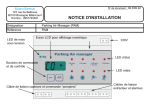
In order to send the measured values or commands to actuators, it is necessary that the probe to be
paired with one or more actuators. This is achieved through "the LCD tools" temporarily mounted on
the probe. Details are described in the document “Setting the E4000 air quality probe in EnOcean sensor
mode”
LCD tool connectors
LCD tool
Beside, for temperature control, EnOcean sensors can be associated with the E 4000 probe (Ex: window
handle to turn off the heating when open, presence sensor or card to switch to ECO mode)
7.2.4.2. Telegram Transmission Principle
In EnOcean sensor mode
The probe sends a telegram of a different profile every 5 seconds (if paired).
Without annex probe, the E4000 probe is sending 5 telegrams (1 for ventilation control, 1 for CO2 +
Temperature & Humidity, one for VOCs, 1 for heater control, 1 for cooling control) so a 25 to 30
seconds cycle.
Telegram emissions are not conditioned by changes of measures because emission rate is enough vis-àvis the HVAC.
This rate is not adjustable.
In EnOcean gateway mode, the probe sends telegrams according to events.
7.2.4.3. Description Radio Telegram
In EnOcean sensor mode
EnOcean profiles:
The following telegrams are sent:
• Controls for ventilation (Bi Directional)
• Or Commands for continuous ventilation (uni-directional)
• Or Commands for single-speed ventilation (ON/OFF)
• Or Commands for Two-speed ventilation (ON/OFF)
• And CO2, Humidity and temperature Measurements
• And VOCs Measurement
(EEP 4BS: A5-20-02)
(EEP RDS: F6-02-01)
(EEP RDS: F6-02-01)
(EEP RDS: F6-03-01)
(EEP 4BS: A5-09-04)
(EEP 4BS: A5-09-05)
And for temperature heating control:
• Control valve battery operated (Bi Directional)
• Or Control valve Basic (Bi Directional)
• Or Control valve wired (Bi Directional)
• Or Control Generic HVAC Interface (Bi Directional)
• Or Temperature (setting + measure)
(EEP 4BS : A5-20-01)
(EEP 4BS : A5-20-02)
(EEP 4BS : A5-20-03)
(EEP 4BS : A5-20-10)
(EEP 4BS : A5-10-03)
www.nano-sense.com
All Rights Reserved
Tel : 33 (0)1 41 41 00 02
page 10/22
Guide d’Installation sonde E4000
E4000 probe Installation Guide
And for temperature cooling control:
• Control valve battery operated (Bi Directional)
• Or Control valve Basic (Bi Directional)
• Or Control valve wired (Bi Directional)
• Or Control Generic HVAC Interface (Bi Directional)
• Or Temperature (setting + measure)
(EEP 4BS : A5-20-01)
(EEP 4BS : A5-20-02)
(EEP 4BS : A5-20-03)
(EEP 4BS : A5-20-10)
(EEP 4BS : A5-10-03)
And, if annex probes are installed:
• Radon Measurement
• And or Particles Measurement
• And or Ozone Measurement
(EEP 4BS: A5-09-06)
(EEP 4BS: A5-09-07)
(EEP 4BS: A5-09-05)
The control algorithm is similar to that of the relays (ventilation one or two speeds) and 0-10V output
(continuous ventilation) of the analog module and combines the CO2, VOCs and humidity
measurements.
The thresholds setting of CO2 and humidity (VOC thresholds are regulatory) is active in EnOcean
sensor mode as for the analog module.
In EnOcean gateway mode
EnOcean profiles:
The gateway supports most of the EEP2.1 plus few more telegrams approved since the publication of
the EEP2.1
The only exceptions are CO2 and VOC telegrams, the probe providing already those data. CO is also
not handled
7.2.4.4. Transmission Range
As radio signals are electromagnetic waves, the signal is damped on its way from the sender to the
receiver. That is to say, the electrical as well as the magnetic field strength is removed inversely
proportional to the square of the distance between sender and receiver (E,H~1/r²).
Beside these natural transmission range limits, further interferences have to be considered: Metallic
parts, e.g. reinforcements in walls, metallized foils of thermal insulations or metallized heat-absorbing
glass, are reflecting electromagnetic waves. Thus, a so-called radio shadow is built up behind these
parts.
Building material used in a building is of paramount importance for the evaluation of the transmitting
range. For an evaluation of the environment, some guide values are listed:
Brick walls/
Aerated concrete blocks
(ACB)
20 meters through
maximum 3 walls
www.nano-sense.com
Plaster board/
Wood (dry)
30 meters through
max. 5 walls
All Rights Reserved
Reinforced concrete
10 meters through
maximum
1 wall/ceiling
Tel : 33 (0)1 41 41 00 02
page 11/22
Guide d’Installation sonde E4000
E4000 probe Installation Guide
Other materials
Air (Visual contacts)
Windows with thermal insulation
Typical range
30m in passages, corridors, up to 100m in halls
5m through 1 Window maximum
Supply blocks and lift shafts should be seen as a compartmentalisation
In addition, the angle with which the signal sent arrives at the wall is of great importance. Depending on
the angle, the effective wall strength and thus the damping attenuation of the signal changes. If possible,
the signals should run vertically through the walling. Walling recesses should be avoided.
Other Interference Sources
Devices that also operate with high-frequency signals, e.g. computer, audio-/video systems, electronical
transformers and ballasts etc. are also considered as an interference source.
The minimum distance to such devices should amount to 0,5m.
Find the Device Positioning by means of the Field Strength Measuring Instrument EPM100
EPM 100 is a mobile tool for measuring and indicating the received field strength (RSSI) of the
EnOcean telegrams and disturbing radio activity at 868,3MHz. It supports electrical installers during the
planning phase and enables them to verify whether the installation of EnOcean transmitters and
receivers is possible at the positions planned. It can be used for the examination of interfered
connections of devices, already installed in the building.
8. Insert gas sensors
8.1.
Sensors on miniSD card
CO2
COV
CO2 and COV sensors are supplied in sealed waterproof bags
.Introduce them into the slot
located on the back side of the card.
Well comply with locations.
Do not open pouches until ready to
install sensors.
Press until it clicks. The sensor
should not pop up.
Insert the sensor when the motherboard is ready to be turned on.
www.nano-sense.com
All Rights Reserved
Tel : 33 (0)1 41 41 00 02
page 12/22
Guide d’Installation sonde E4000
8.2.
E4000 probe Installation Guide
CO2 NDIR Sensor
NDIR Sensor
CO2 NDIR Sensor Connectors
9. Powering
At power up, the red status LED will flash alternatively with the green LED during the initial phase of
gas sensors conditioning (20 minutes), and finally the green LED will flashes every 2 seconds indicating
the good functioning of the probe. During this gas sensors conditioning phase ventilation, heating and
cooling commands are minimal.
Main board status LEDs
The red LED indicates defaults.
The type of failure is indicated by the number of LEDs flashing ("message") in the following order of
priority of default detected:
1 flash: Voltage too high (>35V DC or 25V AC)
2 flashes: low voltage (<15V DC or 10.6V AC)
3 flashes: Calibration EEPROM defective
4 flashes: Humidity sensor defective (out of range)
5 flashes: Faulty temperature sensor (out of range)
There is a break of 2 seconds between each "message"
If the red LED is continuously ON, it indicates that a KNX Bus, LON or POE daughter board has been
detected but communication with the board has failed.
Each location of gas sensor also includes a red LED.
At power up, if no sensor is detected, both LEDs turn red permanent.
If a sensor is detected and the test is negative, the LED blinks rapidly.
If the test result is positive, the LED goes out.
When the sensor reaches the end of life (10 years) the red LED turns ON to request his replacement.
The countdown is on board the sensor module.
Sensors Status LEDs
www.nano-sense.com
All Rights Reserved
Tel : 33 (0)1 41 41 00 02
page 13/22
Guide d’Installation sonde E4000
E4000 probe Installation Guide
ATTENTION
After switching On !
If the CO2 solid state sensor has been stored for several weeks, it takes at least 3 days to
get an accurate value.
With firmware before December 13th 2013, starting values can commonly exceed 2500
ppm then decrease gradually.
With firmware after December 13th 2013, starting value is 390ppm and the sensor will
gain in sensitivity gradually.
www.nano-sense.com
All Rights Reserved
Tel : 33 (0)1 41 41 00 02
page 14/22
Guide d’Installation sonde E4000
E4000 probe Installation Guide
10. Configuration (EnOcean, Modbus RS485 and
Analogical Board)
10.1. Position the micro switches
Two dry contacts of analog board (speed 1 and 2) or RS485 & EnOcean commands operate based on
CO2, VOCs and RH parameterized thresholds by three micro switches:
Position 1
H
Position 2
L
# 1 Thresholds: CO2: 500 ppm or 900
(selectable) / 0.5 ppm formaldehyde
equivalent (VOCs) or 75% RH over 20
minutes. H = High / L = Low
# 2 Thresholds: CO2: 1250 or 1800ppm
(selectable) or 3 ppm formaldehyde
equivalent (VOCs) or 85% RH over 5
minutes. H = High / L = Low
# 1&2 Operating action contact: Normally
Open (NO) or Normally Closed (NC).
Position 1
NO
Position 2
NC
In EnOcean sensor mode: Unique
threshold selection # 1 or # 2 (# 1= NO, #
2 =NC)
Dry contacts type: Isolation 3750 Vrms / 1 min, 30VDC / 0.6 A max.
Hysteresis of contacts: CO2: 100 ppm, VOC: 10% of the formaldehyde threshold equivalent, RH: 10%
of the threshold.
0/10V output is a mix of CO2, VOC and humidity (with an OR function: the most significant prevailing
over others). The speed 1 threshold corresponds to 0.68V and 5.32V threshold to speed 2. Nevertheless
there is always a minimum of 10% ventilation so 1V.
www.nano-sense.com
All Rights Reserved
Tel : 33 (0)1 41 41 00 02
page 15/22
Guide d’Installation sonde E4000
E4000 probe Installation Guide
CO2 Baselines expressed in ppm
200 000
Lethal (deadly) for humans
100 000
Lethal in 10 minutes without an action for resuscitation
40 000
Threshold of irreversible effects on health
5000
Maximum concentration on workplace (8h)
4000
Bedroom poorly ventilated
1000
Significant decrease in intellectual performance. Factor for asthma or
building syndrome. Maximum value allowed inside buildings.
390
Outside air
10.2. Connection diagram according to position of micro
switches
Connection with negative
logic (NC) for one speed
ventilation.
The two micro-switches 1
and 2 in NC position.
Connection with positive
logic (NO) for one speed
ventilation.
The two micro-switches 1
and 2 in NO position.
Connection with positive
or negative logic for two
speed ventilation.
The two micro-switches
in the position proper to
each speed.
To ventilation
11. Completion of installation
By clipping close the cover (the cover is symmetric and therefore can be mounted upside down)
Apart from domestic installations, it is preferable to secure the cover using the two screws.
The cover and housing have pre lateral holes.
www.nano-sense.com
All Rights Reserved
Tel : 33 (0)1 41 41 00 02
page 16/22
Guide d’Installation sonde E4000
E4000 probe Installation Guide
ANNEXES
1. Installation of BUS connections
1.1
RS485
RS485 Modbus Connection
- (A)
+ (B)
Shielding of the cable *
cable
* : Never connect to the – of the power supply.
RS485 Modbus connection is not optically isolated. Therefore, you must pay special attention during
the installation procedures that they do not cause communication failures or does not damage the RS485
coupler. Follow the points in the table below to ensure proper operation of your communication.
1
Use a shielded bus cable and connect one end of the shield to ground. Make sure, wherever
possible, that there is no break in the cables. If this is not possible, you must have shield continuity
consistent with the EMC at the connection points.
2
Keep RS485 cables away from other cables like power cables for example.
3
Connect the shielding to one end grounded to ensure equipotentiality of the shield.
No other grounding is required.
The "Shield" terminal of the power supply terminal block is isolated and is intended to facilitate the
continuity of shielding.
THE SHIELD BUS MUST NOT BE CONNECTED TO THE “-“ OF THE BUS.
Warning: If you do not comply with above, the interface may be destroyed.
4
Make sure electrical signals are correct for the bus cable. This sets the resting level of the signal
between two posts and is important for identifying the beginning of a message. The E4000 probe
produces a 5V electrical signal. The voltage between the data lines + (B) and - (A) should be
between 0.5 and 1V.
5
For bus cable lengths over 100m, make sure to activate the bus termination at both ends. A bus
termination on one side only is sufficient for shorter distances. Bus termination, on E4000 probe
side, is provided by a jumper (see picture below).
6
The polarization of the bus is also highly recommended using the two other jumpers.
RS485 standard requires a differential level of 200 mV for the signal detection. If the RS485 is not
polarized, this level will not be reached at rest (without communication on the line) and then the
operation will not be guaranteed. For this, a bias is applied to only one point of the bus. It is
preferably applied to the master side.
Activation of the RS485 bus termination
and polarization by placing three
jumpers.
www.nano-sense.com
All Rights Reserved
Tel : 33 (0)1 41 41 00 02
page 17/22
Guide d’Installation sonde E4000
1.2
E4000 probe Installation Guide
Programming the physical address
In slave mode, it is possible to program directly the probe address by using buttons on the LCD tool.
(up to address # 255). A default address is implemented and the probability that two sensors have the
same address is 1 / 250 which prevent setting. See document “Setting the E4000 air quality probe in
RS485 mode”
« Paramétrage de la sonde de qualité de l’air E4000 en mode capteur RS485 »
1.3
Choice between RTU and ASCII
Thanks to the LCD tool, it is possible to choose between ASCII and RTU. Default bus is RTU.
1.4
RS485Annexes probes
When a daughter board is installed (EnOcean, KNX, LON, POE), the motherboard interrogates annex
probes and the bus becomes the master. Data from annex probes are sent via the daughter card. The bus
in this case is in ASCII mode. Check that annex probes Radon, Particle and or Ozone are in ASCII
mode or version.
Select the address of each annex probe between 1 and 32.
If the E4000 probe detects several probes of the same type, it will only take into account the first
detected (lowest address).
www.nano-sense.com
All Rights Reserved
Tel : 33 (0)1 41 41 00 02
page 18/22
Guide d’Installation sonde E4000
E4000 probe Installation Guide
2. Choosing Cable Bus
2.1. RS485
The RS422 standard recommends 24AWG (0.23mm2) twisted pair cable with a capacity of 16 pF shunt
per foot and 100 ohm characteristic impedance. Although the standard does not specify anything for
RS485 wiring, the cable can perfectly be used for RS485.
2.1.1.
Topology
The topology of RS485 cabling must be observed. The cable must go to the first bus coupler device,
leave the first device to the second, etc. .. until the last device.
The topologies in tree, branch or star are not allowed.
2.2. KONNEX
Connector for complementary 31 V DC KNX power supply REQUIRED
Programming key
Programming LED
KNX connector
Use twisted pair cable KNX certified (green)
Board and bus being connected, press the programming button.
The programming LED lights on. Beware if the bus is not connected, the interface KNX board will not
be powered and the motherboard cannot communicate with it. (Red LED continuous).
The probe is in programming mode.
Commissioning and configuration of the probe is made via ETS (KNX Tool Software).
For the setting details, refer to the KNX manual setting.
2.3. LONWORKS
Connector for power supply 15-31V DC
Connector for LON bus
Use twisted pair cable recommended for LON:
Generic 16AWG cable (1.3mm diameter) (similar to Belden 8471 or 85102)
Cable NEMA Level 4 (This cable is not equivalent to TIA Category IV cable)
TIA Category 5 cable
JY (St) Y for specific applications in Europe.
Commissioning and configuration of the probe is made via LONMAKER software or equivalent.
For the setting details, refer to the LON manual setting
www.nano-sense.com
All Rights Reserved
Tel : 33 (0)1 41 41 00 02
page 19/22
Guide d’Installation sonde E4000
E4000 probe Installation Guide
2.4. POE
Use an Ethernet cable
3. Ventilation Control
The different measurements are used to control the ventilation based on applications.
The table below summarizes which sensor to use for each application:
Control
Application
Office
Individual
Open space
Meeting room
Small
large
Amphitheatre
Restaurants
Main room
Kitchen
Public buildings
Swimming pool /
Hospitals
Theatres
Other
Housing /Hotels
Bath rooms
Bed rooms
Living rooms
Industrials
premises
Shops
Parking, Garages
NA
*
**
***
CO2
CO2 NDIR
VOC
Humidity
Temperature
Particles
NA
NA
NA
NA
NA
NA
NA
NA
NA
NA
NA
NA
*
**
NA
NA
NA
NA
NA**
NA***
Especially recommended
NA**
NA
NA
NA
NA
NA
NA**
NA**
NA
NA
NA
NA**
Satisfactory
Not Adapted
The environment is too aggressive for CO2 solid state gas sensors because of recurring chlorine
vapors. Use NDIR optional sensor
With regular change of sensor
Use of CO sensors and specific Low Speed, High Speed management.
NanoSense offers specific solutions for car parks.
Note that a humidity outdoor sensor and/or a temperature outdoor sensor can be coupled with E4000’s
humidity and temperature sensors to optimize ventilation.
Example:
If indoor air is too humid (risk of developing mites) and outdoor air is drier, an air renewal will lower
the inside humidity. On the contrary, if the outside air is more humid than indoor air, we can only play
on the temperature.
A Particles sensor, a Radon sensor and an Ozone sensor (under development) can be handled by the
E4000 probe with specific associated control.
www.nano-sense.com
All Rights Reserved
Tel : 33 (0)1 41 41 00 02
page 20/22
Guide d’Installation sonde E4000
E4000 probe Installation Guide
4. Specification
Power supply from 15 to 33V DC and from 12 to 24V AC (preferably DC to minimize ageing)
Consumption on KNX or LON bus: 9mA max (only for interface board)
Consumption on 24V AC or 31V DC: 45 mA (+10 mA during RS485 communication)
RS485 bus interface resident
KNX bus interface module: Optional board (TP1 / E mode)
LON bus interface module: Optional board
EnOcean: Optional radio module
Analog: 2 dry contacts and 1-10V: Optional board
Ambient temperature range: 0 ° C to +45 ° C
Protection class: III
Protection grade: IP 30
Applicable Standard: EN 60730-1 (electrical controls for household machines and the like)
Case: 135 x 90 x 28 mm
The unit complies with European Directive 73/23/EEC (Low Voltage Directive) and 89/336/EEC (EMC
Directive).
KNX:
The ETS database and the LON Plug-In are available on line on www.nano-sense.com
www.nano-sense.com
All Rights Reserved
Tel : 33 (0)1 41 41 00 02
page 21/22
Guide d’Installation sonde E4000
E4000 probe Installation Guide
DRILLING
This drawing is at scale one and can be use directly for drilling in removing this sheet.
www.nano-sense.com
All Rights Reserved
Tel : 33 (0)1 41 41 00 02
page 22/22