1
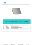
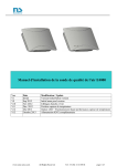
P4000 Particulate matter probe Installation manual
Ver
V1
V2
V3
Date
Initial
04/2015
27/04/2015
www.nano-sense.com
Modification / Update
Version Initial/Initial version
Stop bits settable for RTU version
EnOcean version added
All Rights Reserved
Tel : 33 (0)1 41 41 00 02
page 1/11
Guide d’Installation sonde E4000
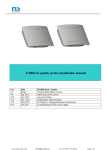
E4000 probe Installation Guide
Summary
1.
2.
3.
4.
5.
6.
6.1.
6.1.1.
6.1.2.
6.2.
7.
8.
9.
10.
11.
Security
Positioning
Installation
Wiring
Motherboard preparation
Connecting
Power Supply
Power Supply Characteristics
Power supply connection
Connecting to the Bus
Powering
EnOcean Pairing
EnOcean Transmission rate
Completion of installation
Maintenance
3
3
4
4
5
5
5
5
5
6
6
6
6
6
7
ANNEXES
1.
1.1
1.2
1.3
1.4
1.5
1.6
1.7
2.
3.
8
Installation of BUS connections
RS485
Programming the physical address
Control On Off
Stop bits setting
Choice between RTU and ASCII
Choosing Bus Cable
Topology
Specification
EnOcean Profile
8
8
9
9
9
9
9
9
10
10
DRILLING
www.nano-sense.com
11
All Rights Reserved
Tel : 33 (0)1 41 41 00 02
page 2/11
Guide d’Installation sonde E4000
E4000 probe Installation Guide
1. Security
WARNING
Danger of death, risk of electric shock and fire!
The installation should only be undertaken by a qualified electrician!
To apply for correct bus and power cables and to activate the device, comply with the state of the art
and standards.
Any intervention or modification to the device will invalidate any warranty claim.
• Use the probe only with secured low voltages!
• Use an external 12 to 24VAC or DC power supply capable of delivering 60mA per probe and ensuring
a peak voltage under 40V.
2. Positioning
The position of the probe is crucial vis-à-vis efficiency and energy savings for
ventilation.
• The probe is designed to ensure air quality; it must be placed in the area of
occupancy of the premise served by outlet vents, on a wall at eyes level
(breathing human level, between 1.5 and 1.8m).
• Avoid drafts (near openings, blowing air, doors, outlet vents) and dead zones
(niche, shelves and curtains).
• Avoid orthogonal walls (corners of room in particular)
• Avoid heat sources and the proximity of occupants (radius of 1 m from
workstation).
• Avoid direct exposure to sunlight.
• Position the sensor vertically on a wall or partition.
This device is not intended for installation in duct or ceilings.
Any work not in accordance with this documentation or
changes to the device will invalidate all warranty claims.
www.nano-sense.com
All Rights Reserved
Tel : 33 (0)1 41 41 00 02
page 3/11
Guide d’Installation sonde E4000
E4000 probe Installation Guide
3. Installation
Attach to the wall through two holes in the case.
TOP
Take care of case orientation (TOP –BOTTOM)
Screws with flat heads, diameter 3mm
BOTTOM
Make sure to position the hole of cables
path at the case bottom
4. Wiring
Be careful, wiring must be sealed. Incoming air, even slight, would seriously jam the temperature,
humidity and air quality measures.
When the switchboard is located in the heated volume: caulk arrivals between cables and ducts at the
switchboard level.
When the switchboard is out of the heated volume, caulk between cables and ducts before entering the
heated volume. A sealing plug must also be placed between duct and cable reaching the P4000 probe to
prevent air entry.
When the sealing of the duct is not possible, use a specific sealant.
In case of use of electrical box, select an airtight case with sealing membrane from
which the duct passes through. If the case crosses through the sealing plane
(plasterboard), seal between the casing and panel with a special sealant without
silicone and VOC.
www.nano-sense.com
All Rights Reserved
Tel : 33 (0)1 41 41 00 02
page 4/11
Guide d’Installation sonde E4000
E4000 probe Installation Guide
5. Motherboard preparation
Clip the mother board into the case
The arrow on the board
indicates the top position
Case
6. Connecting
6.1.
Power Supply
6.1.1.
Power Supply Characteristics
Use a power supply between 12 and 24V AC or 15 and 33V DC with a fluctuation of max
value of less than 10%, preferably a DIN rail regulated one.
Make sure the voltage does not overpass 24V AC or 33V DC before connecting to the
P4000 probe.
Take into account the voltage drop in cable to assess the consumption of each sensor.
Consumption is about 1W. This power is primarily used to heat the air thanks to a resistor for generating
an upward air flow in the sensor.
6.1.2.
Power supply connection
Power supply connector
24VAC or 33V DC
It is recommended to connect one pole of the power supply to the ground.
The power supply connector is designed for monofilament cables from 0,6 to 0,8 mm of Ø. Reveal the wire on 5 mm.
It is not necessary to respect the polarity.
www.nano-sense.com
All Rights Reserved
Tel : 33 (0)1 41 41 00 02
page 5/11
Guide d’Installation sonde E4000
6.2.
E4000 probe Installation Guide
Connecting to the Bus
Measures and orders are transmitted via the RS485 Modbus.
The cable must be twisted. For the selection of cable refer to
§Choosing Bus Cable page 9.
For more details on the connection, see annex § Installation of BUS
connections.
WARNING, DO NOT CONNECT A POLE OF BUS TO POWER SUPPLY OR THE GROUND!
7. Powering
When switched on, the red status LED flashes once quickly for the ASCII version, twice for the RTU
version and once for the EnOcean version.
This LED is used to indicate if the optical needs to be cleaned.
8. EnOcean Pairing
For the EnOcean version once the probe started, a short press on the push button sends a pairing
telegram. The maintenance LED flashes briefly one time. For this step, the LED indicating the need to
clean the lens must be turned off.
9. EnOcean Transmission rate
The coding wheel is used to manage the transmission rate of the EnOcean telegrams. In normal mode
(position 0) the probe emits every 30 seconds and the sensor heater is continuously powered. Other
modes to wake the sensor at a defined rate:
Position Operating mode
10measures every:
Lifetime of the sensor
0
Normal (permanent)
continuous
7 years
1
Intermittent
15mn
10 years
2
Intermittent
30mn
28 years
3
Intermittent
1h
> 40 years
4
Intermittent
2h
> 40 years
5
Intermittent
3h
>> 40 years
6
Intermittent
6
>> 40 years
7
Intermittent
12h
>> 40 years
8
Intermittent
24
>> 40 years
9
Intermittent
48h
>> 40 years
At each wake up, the probe waits 5 minutes to stabilize the airflow and sends a measurement every 30
seconds 10 times (so during 5 minutes) and then returns to sleep mode.
10. Completion of installation
By clipping the cover (the cover is symmetric and therefore can be mounted upside down)
www.nano-sense.com
All Rights Reserved
Tel : 33 (0)1 41 41 00 02
page 6/11
Guide d’Installation sonde E4000
E4000 probe Installation Guide
11. Maintenance
The more the sensor is exposed to dust the more it shall be serviced (cleaning lenses with a wet cotton
swab). Do not use alcohol or solvents. Use only clean water.
This sensor does not have a reference beam to compare with the one exposed to dust using therefore
cumulative sensor exposure to dust is used to determine preventive maintenance timing. When
cumulative exposure is exceeded, an LED indicates the need for cleaning.
After cleaning the lens, the counter will be reset by pressing a button (more than 10 seconds).
Acknowledgement is indicated by the turn off of the LED.
The service time is:
PM2.5 Average
< 5 μg/m3
< 10 μg/m3
< 25 μg/m3
< 50 μg/m3
www.nano-sense.com
Each
5000 Days
2500 Days
1000 Days
500 Days
All Rights Reserved
Tel : 33 (0)1 41 41 00 02
page 7/11
Guide d’Installation sonde E4000
E4000 probe Installation Guide
ANNEXES
1. Installation of BUS connections
1.1 RS485
RS485 Modbus
Power supply + or AC
Power supply – or AC
Bus +
Bus - *
* : Never connect to the « - » of the power supply
RS485 Modbus connection is not optically isolated. Therefore, you must pay special attention during
the installation procedures that they do not cause communication failures or does not damage the RS485
coupler. Follow the points in the table below to ensure proper operation of your communication.
1
Use a shielded bus cable and connect one end of the shield to ground. Make sure, wherever
possible, that there is no break in the cables. If this is not possible, you must have shield continuity
consistent with the EMC at the connection points.
2
Keep RS485 cables away from other cables like power cables for example.
3
Connect the shielding to one end grounded to ensure equipotentiality of the shield.
No other grounding is required.
It is possible to connect the shield to ground by connecting to the 0V of the power supply. This can
be achieved by connecting the cable shield of the bus to the – of the power terminal.
THE SHIELD BUS MUST NOT BE CONNECTED TO THE “-“ OF THE BUS.
Warning: If you do not comply with above, the interface may be destroyed.
4
Make sure electrical signals are correct for the bus cable. This sets the resting level of the signal
between two posts and is important for identifying the beginning of a message. The P4000 probe
produces a 5V electrical signal. The voltage between the data lines + (B) and - (A) should be
between 0.5 and 1V.
5
For bus cable lengths over 100m, make sure to activate the bus termination at both ends. A bus
termination on one side only is sufficient for short distances. Bus termination, on P4000 probe side,
is provided by a jumper (see picture below).
6
The polarization of the bus is also highly recommended using the two other jumpers.
RS485 standard requires a differential level of 200 mV for the signal detection. If the RS485 is not
polarized, this level will not be reached at rest (without communication on the line) and then the
operation will not be guaranteed. For this, a bias is applied to only one point of the bus. It is
preferably applied to the master side.
Activation of the bus 485 termination
and polarization by placing three
jumpers.
www.nano-sense.com
All Rights Reserved
Tel : 33 (0)1 41 41 00 02
page 8/11
Guide d’Installation sonde E4000
E4000 probe Installation Guide
1.2 Programming the physical address
It is possible to program directly the probe address by using the rotary switch.
The bus address is selectable from 1 to 20 for the ASCII version and 1 to 10 for the RTU version
The zero of the encoder is either 10 or 20
ASCII version:
To go in the 11-20 range, the jumper shall be positioned as shown below.
Warning: the address is determined at startup. Any change under voltage will not be taken into account.
1.3 Control On Off
The probe can be turned in sleeping mode by a BUS command. By default, at power On, the sensor is in
continuous operation. During the sleeping period, consumption is reduced and the sensor is no longer
powered. For each controlled wake up, the probe waits 5 minutes to stabilize the air flow and during the
stabilization timeof the air flow, the measurements returned by the sensor are at zero.
The sensor life is extended according to the rhythm of wakes. See EnOcean transmission rate chapter 9.
1.4 Stop bits setting
For the RTU version, the here above jumper is used to set the number of Stop bits:
No jumper: 1 stop bit
Jumper :
2 stop bits
Warning: the configuration is determined at startup. Any change under voltage will not be taken into
account.
1.5 Choice between RTU and ASCII
The choice between RTU and ASCII must be determined in the purchase order and depends on the
firmware. It is not possible to change the firmware without a special programming tool..
1.6 Choosing Bus Cable
The RS422 standard recommends 24AWG (0.23mm2) twisted pair cable with a capacity of 16 pF shunt
per foot and 100 ohm characteristic impedance. Although the standard does not specify anything for
RS485 wiring, the cable can perfectly be used for RS485.
1.7 Topology
The topology of RS485 cabling must be observed. The cable must go to the first bus coupler device,
leave the first device to the second, etc. .. until the last device.
The topologies in tree, branch or star are not allowed.
For diagram (e) however a diversions greater than 30 cm is tolerated (vertical links in the diagram (e)).
www.nano-sense.com
All Rights Reserved
Tel : 33 (0)1 41 41 00 02
page 9/11
Guide d’Installation sonde E4000
E4000 probe Installation Guide
2. Specification
Interface:
Digital output RS485 Modbus (see document on the Modbus protocol for details)
Modbus ASCII or RTU (to be specify when ordering)
E4000 IAQ probe compatible for EnOcean, LON or KNX interface (ASCII only)
20 selectable BUS addresses (1 to 10 and 11 to 20 with a jumper in ASCII only).
Number of stop bits selectable (1 or 2 with a jumper in RTU version only)
EnOcean
EEP: 4BS: A5-09-07
Pairing with push button.
Densities of PM1, PM2.5 and PM10 expressed in μg/m3
Density of PM1, PM2.5 and PM10 also expressed in number/m3 (but EnOcean)
Measuring range 0-950 μg/m3 and 0-65 535 000 particles /m3
Resolution 1μg/m3 and 1000 particles per m3
Running average on 30 seconds
The sensor cannot see particles below 0.5μm
Power supply 12 to 24V DC or AC
Power: 1W
Operating Temperature: 0 to 45 °C
Storage temperature: -30 to 60 °C
Lifespan: 7 years (in continuous)
The unit complies with European Directives 73/23/EEC (Low Voltage Directive) and 89/336/EEC
(EMC Directive).
3. EnOcean Profile
RORG A5 4BS Telegram
FUNC 09 Gas Sensor
TYPE
07 Particles
Status: Approved Aug 16, 2011
Offset
0
9
18
27
Size
9
9
9
1
Bitrange
DB3.7...DB2.7
DB2.6...DB1.6
DB1.5...DB0.5
DB0.4
Data
Particles
Particles
Particles
ShortCut
Part
Part
Part
Description
Particles < 10µm (PM10)
Particles < 2.5µm (PM2.5)
Particles < 1.0µm (PM1)
28
1
DB0.3
LRN bit
LRNB
LRN Bit
29
30
31
1
1
1
DB0.2
DB0.1
DB0.0
www.nano-sense.com
All Rights Reserved
Valid Range
0 .. 511
0 .. 511
0 .. 511
Scale
0..511
0..511
0..511
Unit
µg/m3
µg/m3
µg/m3
Enum:
0 : Teach-in telegram
1 : Data telegram
0/1 : PM10 active (*)
0/1 : PM2.5 active (*)
0/1 : PM1 active (*)
Tel : 33 (0)1 41 41 00 02
page 10/11
Guide d’Installation sonde E4000
E4000 probe Installation Guide
DRILLING
This drawing is at scale one and can be use directly for drilling in removing the sheet.
www.nano-sense.com
All Rights Reserved
Tel : 33 (0)1 41 41 00 02
page 11/11