1
6 - REMOTE CONTROLS MEMORIZATION
4 - FEATURES
! Memory for 85 transmitter keys;
! Single tx code memorization and erasure with a single push-button;
! Single tx or full memory erasing;
! Programmable operating mode for the relays : pulse or step;
! Display of the number of stored users;
! 4 inputs for emergency extra push-buttons.
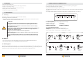
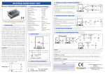
The memorization of the remote controls can be carried on in sequential way, by using only P1.
Each step is confirmed by the led R1, R2, R3, R4.
The procedure consists in a sequence of pressures of P1
The lighting of the leds R1, R2, R3, R4 is cyclic: at each pressure of P1 a led is turned on and the preceding led is turned
off. (fig. 2)
The led light is stable or blinking according to the setting of the corresponding dip-switch. ( see. cap. 8 )
5 - INSTALLATION
5.1 - Positioning
The location choice is very important for the best result of the installation.
The following conditions have to be followed:
- fix the receiver far from interference sources as informatic systems, allarm systems or other radio emissions.
- the distance between 2 receivers should be more than 1,5 m.
R2
R4
R3
Fig. 2
6.1 Relay condition
The relay configuration ( pulse or step ) is displayed by the led light
ATTENTION
1 - The power 12 Vac/Vdc must be provided by a power supplier certified according to
Safety Regulations and must come from a SELV circuit, protected against short circuit.
2 - The appliance must be installed in an enclosure able to assure a Class I or II Safety
Class against electric chock.
!
R1
3 - The protection devices against extracurrents and short circuits must be provided by the
building electric installation when the relays are inserted on the supply of appliances
connected to the distribution network.
LED with stable light :
LED with blinking light :
PULSE Relay
BISTABLE or STEP Relay
6.2 4 keys remote memorization
The memorization consists in a sequence of pressures of P1
Example 2: 4 keys remote memorization with the following links:
Key A --> Relay 1, Key B --> Relay 2, Key C --> Relay 3, Key D --> Relay 4.
4 - Apply a max power of 3,5 KW / 230 Vac to the relay contacts.
In case of connection of the relays to dangerous voltages, foresee a sectioning circuit to
disconnect these parts.
R1 switches off
and on again
R1 lits
R2 switches off
and on again
R2 lits
5 - If there are mixed type loads ( 230V and 12 V ) connected to the relay terminals, these
must be connected by interposing a null relay: example R1=230V, R2=230V, R3= empty,
R4= 12V.
5.2 - Antenna
- if you connect an antenna ( not provided ) fix the wire to the terminal 4 and the shield to the terminal 3;
- if you use the piece of wire ( 16,5 cm ) provided connect it to the terminal 4.
Release
P1
Keep P1 pushed for 2
sec. until LD1
switches on
Release
P1
Press P1
R3 switches off
and on again
R3 lits
5.3 - Auxiliary inputs
Push key A of the
transmitter to
memorize
Push key B of the
transmitter to
memorize
R4 switches off and on
and after 2 sec.
switches off
R4 lits
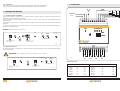
The receiver is equipped with 4 extra inputs ( I1, I2, I3, I4 e COM) which allow to connect 4 NO auxiliary pushbuttons, fot the direct activation of the relays. The push-buttons PR1, PR2, PR3, PR4 on fig. 1 ( not provided ) act on the
relays like the remote controls keys, in pulse or step mode, according to the settings of dip-switch S1.
Press
P1
Release
P1
Push key C of the
transmitter to
memorize
Push P1
Release
P1
Push key D of the
transmitter to
memorize
Fig. 3
4
5
THE SMART LIVING
THE SMART LIVING