1
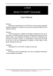
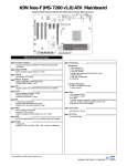
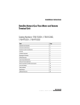
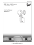
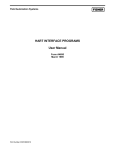
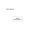
EnSonic
Installation Manual
Document code: 10735.INST.004
____________________________________________________________________________________________________________
EnSonic Installation Manual
10735.INST.004
Document
EnSonic: Installation Manual
Document code
10735.INST.004
Date
June 25, 2003
Publisher
Instromet International N.V.
Rijkmakerlaan 9
B 2910 Essen
Belgium
Phone:
Fax:
Copyright
+32-3-670 0700
+32-3-667 6940
© 2003, Instromet International N.V., Essen, Belgium
Instromet International N.V. is a member of the Instromet group.
All technical and technological information contained in this manual, including
any drawings and technical specifications remain the property of Instromet
International N.V. and may not be used (other than for the operation of this
product), copied, multiplied, passed on or communicated to a third party
without the prior written permission of Instromet International N.V.
Trademarks
Products listed are trademarks of their respective manufacturers. Company
names listed are trade names of their respective companies
Revision History
Revision
002
003
004
Remark
First edition
ACAD drawings implemented
A number of issues added
Date
25-06-2003
4-07-2003
20-01-2004
____________________________________________________________________________________________________________
Page 2 of 18
10735.INST.004
Preface
This document describes the mechanical installation procedure for the EnSonic Energy Measurement
System.
The overall system layout is presented in figure 1. Normally, the EnSonic is installed in the hazardous area as
close as possible to the gas sample point. The gas (pressure between 40 and 80 bar) is led to the EnSonic
using a heat traced tubing. After being analyzed by the EnSonic the gas is vented into the atmosphere via the
vent pipe on the right side of the unit. The auto-calibration system which supplies reference gas to the system
on regular intervals to check the performance is shown on the left side of the unit. During operation the bottle
with reference gas is strapped to the back side of the unit.
The power supplies (24 VDC and 220 VAC) and the M2000 display and control unit are located in the safe
area. The cabling between the unit in the field and the safe area consists of a data, a 24 VDC and a 220 VAC
cable. The data and 24 VDC cable may be combined.
In the safe area the measurement data is presented to the customer via:
a) the analog and digital outputs of the M2000 display and control unit
b) the Instromet Supervisory System
or
c) a user supplied dedicated data logging system
When using the M2000 the user is able to initiate both the auto-calibration and reset function of the EnSonic
remotely via the digital contact inputs of the M2000.
The mechanical installation of the system is described first, the electrical connections are described secondly.
Note: since the EnSonic is installed and operated in the hazardous area where explosive gas
mixtures may be present, the necessary safety precautions should be taken when handling,
installing or operating the system.
The Eex-d box containing the electronics should be de-energized before opening.
Related documents:
‘EnSonic User Manual’
‘EnSonic Programmer’
‘Model 2000 Programmer’
‘Model 2000 Gas Flow Computer’
10735.INST.004
code: 10735.USER.001
code: 10735.ENSCNF.001
code: 10735.M2KCNF.001
code: Model 2000 issue 6, 202/09-02
dd 20-01-2004
dd 25-01-2004
dd 25-01-2004
dd 16-09-2002
Page 3 of 18
vent
drain
4-20 mA
digital out
EnSonic
digital in
empty bottle
detection
Instromet
Supervisory
System
Wobbe: xxxx MJ/Nm3
M2000
reference
gas
heat traced sample line
1/8", 3 mtrs
sample system
24 VDC
220 VAC
line gas, P > 40 bar
hazardous
area
safe area
Figure 1, System Layout
____________________________________________________________________________________________________________
Page 4 of 18
10735.INST.004
1. Mechanical installation
The following items need to be mounted prior to making the electrical connections:
1) the EnSonic Skid
2) the M2000 flow computer
Since the M2000 is the only part that needs to be installed separately from the EnSonic measurement unit
each chapter presents the installation of the M2000 as a separate subject, in cases were no M2000 is used
these sections may be skipped.
EnSonic Skid
The EnSonic measurement system comes mounted on a skid enabling easy field installation. The
recommended way to install the system is to mount the skid on a concrete base taking local regulations into
account. The skid is mounted using M12 bolts (4 pieces) placed on a 450 x 750 mm rectangle (the front of
the EnSonic faces the short side of this rectangle). The dimensions of the skid are presented in Appendix B.
When selecting a suitable place to install the EnSonic the following considerations should be kept in mind:
1)
the unit should be installed as close as possible to the sample point to minimize delay times due
to long sample lines
2)
although not frequently, the reference gas bottle needs replacement so their must be some
space available on the back of the EnSonic to handle the reference gas bottle
3)
the sampled gas is vented from the top of the EnSonic so provisions must be taken to reduce the
build up of high gas concentrations, when necessary local regulations need to be followed
4)
since the EnSonic internally operates at 50 ºC the maximum ambient temperature of the EnSonic
is set at 30 ºC, therefore in some installations the EnSonic may have to be shielded from direct
sunlight
After mounting the EnSonic skid the connection between the sample point for the line gas and the EnSonic
should be made using the heat-traced sample line mounted on the bottom of the unit. This sample line
contains 2 separate 1/8” tubings which are used for the line and the reference gas. The length of the sample
line may be reduced to 2 m to facilitate the installation. An adapter set is included to connect the EnSonic to a
system with 3 mm tubing. The heated tracing should be properly terminated using the provided termination
set.
The reference gas bottle should be properly strapped to the back-side of the skid and the pressure reducing
valve should be installed. The blue wire of the pressure switch should not be damaged. The outlet of the
pressure reducing valve should be connected to the proper inlet of the heat-traced tubing, the length of this
part of the tubing is not critical. At this stage: do not supply pressure to the system!
M2000
The M2000 display and control unit is mounted in the safe area and the M2000 manual should be consulted
for the mechanical installation procedure.
All connectors (: power supply, serial communication ports, analog and digital outputs and digital inputs) are
located on the back side of the unit. Since the twelve digital outputs are opto-coupler based each digital
output requires an additional relay to switch larger currents. These relays have to be mounted on a different
location close to the M2000.
The M2000 is configured via the infra-red serial port located on the front panel of the unit. A serial infra-red
adapter can be fixed to the unit.
10735.INST.004
Page 5 of 18
2. Electrical Installation
The guidelines in this section should be followed to ensure proper functioning of the complete system.
The unit should be properly grounded and connections should be made carefully to ensure long term, failure
free operation.
The electrical installation of the EnSonic is split in two parts:
1) the field connections to the EnSonic measurement system
2) the indoor connections to the EnSonic measurement system and the M2000
Cabling required
Although the measurement data from the EnSonic is present on a 2-wire RS485 serial interface with
MODBUS protocol it is recommended to increase the number of data communication wires to facilitate the
service of the instrument. Therefore the following cabling should be present:
1) Data communication:
a) MODBUS port 2, main measurement data : RS232 or RS485, 2 x 2 shielded twisted pair
b) MODBUS port 1, configuration
: RS232, 2 x 2 shielded twisted pair
b) Ultrasonic unit data & configuration
: RS485, 1 x 2 shielded twisted pair
2) Power supply: nom. 24 VDC, max. 120 W (5 A during startup): 2 wires, shielded
3) Heated tracing: 220 VAC, 3 wires, shielded and armoured
During normal operation MODBUS port 2 of the EnSonic is used to transmit the main measurement data to
the M2000. For configuring and servicing the EnSonic system port 1 is used.
The electronic unit of the ultrasonic velocity of sound measurement unit can be serviced and configured by
Instromet using the RS485 communication port of this unit (however, directly issueing commands to the unit
will interrupt the normal operation of the EnSonic system).
2
All data communication cables may be combined into one 5 x 2 x 0.8 mm armoured shielded cable.
Since the electronics, the internal heating system and the stream selection valve of the EnSonic consume a
reasonable amount of power the resistance of the 24 VDC power supply cable is of importance. To ensure an
input voltage of the system in the field of at least 22 VDC (max. 28 VDC) a low resistance cable should be
selected. As an example: when using a 24 VDC supply as power source the maximum voltage drop of 2 V (:
24 – 22 V) combined with a current of 5 A during startup results in a maximum cable resistance of 0.2 ? per
wire (0.4 ? total). Increasing the input voltage to 28 VDC allows for a cable resistance of 0.6 ? per wire (1.2
2
? total). Although at least a 2 x 2.5 mm armoured shielded cable is recommended the power supply voltage
present on the unit should always be checked. If the remaining voltage drops below 22 VDC a lower
resistance cable and/or a higher voltage power supply needs to be installed.
2
The 220 VAC is used for the heated tracing of the sample line. A 3 x 1.5 mm armoured shielded cable is
recommended.
Field connections
In the field the following connections have to be made to the EnSonic unit.
The 220 VAC power supply is connected to the heat tracing using the terminals in the Eex-e box which is
mounted in the lower left part of the EnSonic cabinet. The heated tracing itself should be properly terminated
using the provided termination set.
The data communication and 24 VDC power supply are connected to terminals located in the Eex-d box of
the EnSonic. To make the connections the cover of the box should be removed using the proper tool. Care
should be taken when handling the relatively heavy cover.
The 24 VDC power supply is connected to the terminal block located on the left side of the temperature
transmitter. The polarity is indicated on the terminals. Checking the actual polarity of the power supply before
making the connections is recommended.
____________________________________________________________________________________________________________
Page 6 of 18
10735.INST.004
The data communication wires are connected to the processor board of the EnSonic located directly above
the 2VOS body. Fig 2 shows the terminal lay-out of this board.
TER 2: Modbus Port 2
RS232: Gnd, Rx & Tx
RS485: A & B
TER 1: Modbus Port 1, RS232
Gnd
Rx
Tx
5
4
3
2
TER 1
1
Gnd
A
B
Rx
Tx
5
4
3
2
1
TER 2
1
1
1
1
24 VDC
1
Fuse 5X20
T3.15A, 250V
+
-
EnSonic computational unit
Figure 2,Terminal lay-out
When making the connections the following should be taken into account:
1) in the Eex-d box the EnSonic computational unit is mounted upside down, consequently the pin
orientation shown in figure 2 must be regarded from left to right (in the box pin 1 is on the left side of
the terminal)
2) TER2 (: terminal 2) is assigned to port 2 which is used for the communication with the M2000. It is
recommended to use the RS485 communication protocol (pin 3 and 4) for this purpose (the required
protocol is selected using the EnSonic configuration software). A twisted pair cable should be used.
3) TER1 (: terminal 1) is assigned to port 1 which is used to configure and check the EnSonic. Since
this port operates in the RS232 mode only, an additional RS232-485 converter may be installed
depending on the cable length in the installation. In this case a twisted pair cable should be
connected to the RS232-485 converter instead of TER1. When the RS232 mode is used two twisted
pair cables should be used.
4) The connection to the ultrasonic measurement unit is not described here since this unit is configured
during the assembly of the EnSonic. The measurement data from the ultrasonic unit is available via
the Modbus registers of the EnSonic. This connection is only to be made by qualified Instromet
employees.
5) The shielding of the data communication cable should be properly connected following the installation
instruction of the Eex-d cable gland.
6) The intrinsic safe connection of the empty bottle detection should be checked: the blue wire from the
pressure switch mounted on the pressure reducing valve of the bottle with reference gas should be
connected to the barrier located on the left side of the box.
Remark:
At the time of writing this document an alternative method to connect the data communication wires to the
unit has been implemented. To the left of the Power Supply terminals a number of terminals is available for
the communication wires:
Upper row labeled 1, 2, 3 and 4 -> Port 2: Tx, Rx & Gnd and Port 2: RS485-A
Lower row labeled 5, 6, 7 and 8 -> Port 1: Tx, Rx & Gnd and Port 2: RS485-B
Which method will be used finally is not yet known.
10735.INST.004
Page 7 of 18
Indoor connections
The following connections should be made in the safe area.
The 220 VAC power supply should be properly connected to the power supply cable of the heated tracing.
Before supplying power the grounding of the cable should be checked.
A 24 VDC power supply should be connected to the 24 VDC power supply cable of the unit in the field. Before
powering the unit the polarity should be checked.
The following connections should be made to the M2000 (all connectors are available on the backside of the
unit), see fig 3.
1) a 24 VDC power supply should be connected to the power input of the M2000 on the left side (the power
output is used to supply power to the relays connected to the digital outputs)
2) the serial data communication cable should be connected to SKT1 (female 9-pin sub-D connector) on
the MPU board located on the right side:
a. when in RS232 mode: pin 2 (:TX), 3 (: RX) and 5 (: GND) must be used
b. when in RS485 mode: pin 6 (: A) and 9 (: B) must be used
3) on the output module the following connections are available:
a. digital outputs which need to be connected to the corresponding relays (A1 / B1, …., A12 / B12)
b. analog outputs (pin A13 / B13, A14 / B14, A15 / B15 and A16 / B16)
Figure 3, Backpannel M2000
4) Three digital inputs are located on the input module (A1, B3 and A3), two of these inputs need to be
connected to the control system of the user. Since the function assignment is software selectable using
the M2000 configuration software the actual mapping of the connections to the digital input is not
important. Jumpers 6, 8 & 10 on the input board have to be fitted.
The connections should be made according to the figure in appendix F.
For the detailed specification of the in- and outputs the manual of the M2000 has to be consulted.
____________________________________________________________________________________________________________
Page 8 of 18
10735.INST.004
3. Powering up the EnSonic
After installing the unit and making the electrical connections the unit can be powered up using the following
procedure:
1) The 24 VDC power supply to the M2000 can be switched on and after a few seconds the M2000
should present readable information on it’s screen. If not, the power supply should be switched off
immediately and the error should be traced.
2) The 24 VDC power supply to the EnSonic unit in the field can be switched on and the following
checks should be performed immediately (only for visibility reasons it is recommended to leave the
cover of the Eex-d box removed, however check for the presense of explosive mixtures before
energising the unit):
a. The three red LED’s on the EnSonic processor board should start blinking, after a few
seconds the LED’s should be blinking simultaneously which indicates proper communication
with the other devices in the system. If one of the LED’s is not lit or does not blink most likely
a communication failure exists with one of the devices in the system.
b. The two LED’s on the EnSonic interface board should blink simultaneously. The LED’s may
be difficult to see since they are located on the far end of the board. If one of the LED’s is not
lit or does not blink most likely a communication failure exists with one of the devices in the
system.
c. Initially, the screen of the PID controller should indicate ‘Startup’. After a few seconds the
upper line on the display should indicate ‘UFL’ (: UnderFLow) while the lower line shows the
set temperature of 50.00 ºC. This underflow condition is to be exepected since the
temperature of the 2VOS body will initially be outside of the span of the temperature
transmitter which ranges from 45 ºC to 55 ºC. When the body temperature rises above the
lower limit of the range the PID controller will start indicating the actual body temperature.
d. The three LED’s on the processor board of the ultrasonic meter should be lit or blinking.
These LED’s may be difficult to see since they are located on the far end of the board. The
green LED indicating a proper power supply should be lit continously. The yellow LED should
be blinking once per second indicating the transmission of data on the serial communication
port. The red LED should be blinking at high rate indicating the measurement rate of the
ultrasonic unit.
e. The bright white LED on the sensor of the CO2 analyser should be blinking regularly and the
small red LED which lites directly after startup should be switched off after a few seconds.
f. One or more LED’s on the barrier of the empty bottle detection should be lit.
If any of these conditions is not met the power should be switched off immediatley and the cause
of the error should be traced.
3) The data communication between the unit in the field and the M2000 can be checked by watching
the measurement results presented on the screen of the M2000. To achieve this the following
keystrokes should be entered on the front panell of the M2000:
a. Press the F4 button under the word ‘Menu’ displayed on the screen
b. Press the upper or lower arrow key on the right side of the screen until the item GAS DATA
is visible and highlighted
c. Press the ENTER key to select this item
d. In the displayed menu select RECEIVED to view the actually received calculation results, use
the arrow keys to view the different pages.
Although the data itself should not be displaying proper or meaningfull values, the trailer of the data
should indicate ‘OK’. If the trailer indicates ‘ALM’ or ‘NA’ proper communication with the unit in the field
is not established. If the communication fails the settings of both communication ports should be
checked using the configuration software.
4) The 220 VAC power supply to the heated tracing can be switched on. After a while the temperature
of the tracing should rise. If not, the connections should be checked.
10735.INST.004
Page 9 of 18
After successfully completing the first 2 of the above 4 steps a PC or laptop with the EnSonic configuration
software should be connected to communication port 1 of the EnSonic processor board. Depending on the
use of a RS232-485 converter in the Eex-d box an additional RS485-232 converter may be necessary to
make the proper connection. When necessary (and allowed!) a direct connection between a laptop and port 1
of the EnSonic processor board can be made in the field. However, check for the presense of explosive
mixtures before doing this!
By running the EnSonic configuration software the performance of the system can easily be checked. The
software itself is described in more detail in the corresponding manual.
Using an infra-red serial adapter and the M2000 configuration software the M2000 can easily be configured.
The M2000 configuration software is described in more detail in the corresponding manual.
It is good practise to upload and save the original settings of the EnSonic and the M2000 when the unit is
working properly after the system has been powered up for the first time.
____________________________________________________________________________________________________________
Page 10 of 18
10735.INST.004
4. Troubleshooting
This section describes some procedures to troubleshoot the EnSonic system.
After switching on the 24 VDC power supply the unit in the field does not start-up properly or behaves
irratically:
The voltage level of the power supply should be checked on the unit itself. If the level falls below 21
Volts a lower resistance cable or a power supply with a higher voltage level should be used.
The three red LED’s on the EnSonic processor board or the 2 LED’s on the interface board do not blink
simultaneously:
In Appendix C and D all possible LED states are presented. Most likely one or more of the devices in
the system is not communication properly with the processor or interface board. Check the operation of
the individual devices by looking at their status LED’s or check their power supply.The baud rates and
HART addresses of the different devices can be set using the EnSonic configuration software.
However, since these values are factory set errors are not likely to occurr in these settings.
There is no communication between the unit in the field and the M2000:
Switch the A & B wire of the RS485 communication either on the unit in the field or on the backside of
the M2000.
Check the settings of the communication ports using the EnSonic configuration software and the
M2000 configuration software. Both ports should have the same settings (baud rate: 38400).
The proper Modbus register configuration must be assigned to port 2. Two different settings can be
configured and the setting of port 2 must resemble the setting expected by the M2000.
The M2000 requires a so called stream number, if the stream number is not set the M2000 is simply
not polling the EnSonic unit for measurement data. Use the M2000 configuration software to set the
stream number.
After switching the 24 VDC power on and off the system has lost it’s configuration and clock settings:
Both the M2000 and the EnSonic processor board come with a lithium battery to save their settings.
The battery back-up must be switched on by setting a dip-switch on the board which is normally done
during assembly of the units. The dip-switch settings for the EnSonic and the M2000 are presented in
appendix E.
The dip-switches of the EnSonic are located on the processor board, to set the dip-switches of the
M2000 the small black plastic cover on the side of the M2000 has to be removed carefully.
The EnSonic configuration software is not able to communicate with the EnSonic processor board:
Check the wiring and the COM:-port settings of the configuration software. When in RS232 mode:
switch the TX and RX lines. When in RS485 mode: check the settings of the converters and/or try to
communicate via the RS232 mode, to achieve this it may be necessary to connect a lap-top directly to
the unit in the field (check for explosive atmospheres before doing this!)
Some modern PC’s or laptops mimic serial COM:-ports via one of their USB ports. Be sure that the
serial COM:-port is actually working. Experience revealed that ‘Edgeport’ USB to RS232 converters do
function properly under Windows XP.
The M2000 configuration software is not able to communicate with the M2000:
Communication via the infra-red port can be time consuming. The infra-red adapter should be fixed
properly to the M2000. Check the COM:-port settings of the configuration program and the M2000
(baud rate: 38400).
Some modern PC’s or laptops mimic serial COM:-ports via one of their USB ports. Be sure that the
serial COM:-port is actually working. Experience revealed that Edgeport USB to RS232 converters do
function properly under Windows XP.
10735.INST.004
Page 11 of 18
Appendix A, Specifications
Skid
Overall Dimensions
Mounting
Weight
: 1900 x 800 x 600 mm
: 4 x M12, rectangle 450 x 750 mm
: approx. 80 kg
Electrical
Power supply
EnSonic : 21 - 28 VDC / 2.5 A / 60 Watt
M2000
: 21 - 28 VDC
Tracing
: 220 VAC
Communication
EnSonic data
EnSonic service
US data & service
: RS 485 or RS232 , MODBUS RTU or ASCII
: RS 232, dedicated protocol
: RS 485, dedicated protocol
Cable requirements:
2
Data
: 5 x 2 x 0.8mm , twisted pair, shielded & armoured
2
24 VDC
: 2 x 2.5 mm , shielded & armoured
See remarks about power supply before installing power supply cable!
2
220 VAC
: 3 x 1.5 mm , shielded & armoured
____________________________________________________________________________________________________________
Page 12 of 18
10735.INST.004
Appendix B, Skid Dimensions
Figure B.1: Skid 3D-view
SE: 1876102
NAME:
REV DWN.
SKID ENSONIC, 3D VIEW
0
HMS
DATE
CHD.
CH. REQ.
COPYHOLDERS
01.07.03
MATERIAL: BEAM 50x50x3
AMERICAN
PROJECTION
SCALE:
UNITS IN:
mm
ROUGHNESS ACCORDING
NEN 3634
THIS DRAWING IS A CONFIDENTIAL DISCLOSURE LOANED SUBJECT TO
THE CONDITIONS THAT IT OR ANY INFORMATION CONTAINED THEREIN
WILL NOT BE USED IN ANY WAY DETRIMENTAL TO OUR INTERESTS
AND THAT ALL COPIES BE RETURNED IMMEDIATELY ON DEMAND.
INSTROMET B.V.
10735.INST.004
SHAPE- AND POSITIONAL
TOLERANCES ACC. NEN-ISO 1101
DRAWING NUMBER
SKID_3D
Munstermanstraat 6, 7064 KA Silvolde Tel +31(0)315 338911 Fax 338679 E-mail: [email protected]
Page 13 of 18
Figure B.2: Skid Topview
SE: 1876102
NAME:
REV DWN.
SKID ENSONIC, FRONT VIEW
0
DATE
CHD.
CH. REQ.
COPYHOLDERS
HMS 01.07.03
MATERIAL: BEAM 50x50x3
AMERICAN
PROJECTION
SCALE:
UNITS IN:
mm
ROUGHNESS ACCORDING
NEN 3634
THIS DRAWING IS A CONFIDENTIAL DISCLOSURE LOANED SUBJECT TO
THE CONDITIONS THAT IT OR ANY INFORMATION CONTAINED THEREIN
WILL NOT BE USED IN ANY WAY DETRIMENTAL TO OUR INTERESTS
AND THAT ALL COPIES BE RETURNED IMMEDIATELY ON DEMAND.
INSTROMET B.V.
SHAPE- AND POSITIONAL
TOLERANCES ACC. NEN-ISO 1101
DRAWING NUMBER
SKID_FRONT
Munstermanstraat 6, 7064 KA Silvolde Tel +31(0)315 338911 Fax 338679 E-mail: [email protected]
____________________________________________________________________________________________________________
Page 14 of 18
10735.INST.004
Figure B.3: Skid Frontview
SE: 1876102
NAME:
REV DWN.
SKID ENSONIC, TOPVIEW
0
DATE
CHD.
CH. REQ.
COPYHOLDERS
HMS 01.07.03
MATERIAL: BEAM 50x50x3
AMERICAN
PROJECTION
SCALE:
UNITS IN:
mm
ROUGHNESS ACCORDING
NEN 3634
THIS DRAWING IS A CONFIDENTIAL DISCLOSURE LOANED SUBJECT TO
THE CONDITIONS THAT IT OR ANY INFORMATION CONTAINED THEREIN
WILL NOT BE USED IN ANY WAY DETRIMENTAL TO OUR INTERESTS
AND THAT ALL COPIES BE RETURNED IMMEDIATELY ON DEMAND.
INSTROMET B.V.
10735.INST.004
SHAPE- AND POSITIONAL
TOLERANCES ACC. NEN-ISO 1101
DRAWING NUMBER
SKID_TOPVIEW
Munstermanstraat 6, 7064 KA Silvolde Tel +31(0)315 338911 Fax 338679 E-mail: [email protected]
Page 15 of 18
Appendix C, LED Status Indication EnSonic Processor board
The 3 red LED’s located on the processor board of the EnSonic computational unit provide full information
about its current status. Depending on the operation mode the following LED combinations are supported:
When in MAIN PROGRAM (: normal operation) mode the following 3 condition groups can be distinguished:
Operating conditions:
LED 1 LED 2 LED 3
FLASH FLASH FLASH
OFF
FLASH OFF
Status definition
LED_OK
LED_WAIT_STATE
ON
LED_UNKNOWN
FLASH
ON
Fault conditions:
LED 1 LED 2 LED 3
FLASH ON
FLASH
FLASH OFF
FLASH
Warning conditions:
LED 1 LED 2 LED 3
FLASH FLASH ON
FLASH FLASH OFF
ON
FLASH FLASH
OFF
FLASH FLASH
Status definition
LED_DATA_FAULT
LED_INPUT_BOARD
Status definition
LED_HART_SENSOR
LED_ULTRASONIC
LED_CO2_METER
LED_OTHER
Remark
OK
Waiting for system power
up
Unknown state
Remark
Data fault
Input board fault
Remark
Hart Sensor
Ultrasonic
CO2 meter
Other
When in BOOT PROGRAM mode (used by Instromet to update the embedded software) the following LED
combinations are supported:
LED 1
FLASH
FLASH
FLASH
FLASH
LED 2
ON
OFF
ON
OFF
LED 3
ON
OFF
OFF
ON
Status definition
LED_PROGRAM_CORRUPTED
LED_PROGRAM_OK
LED_PROGRAM_DOWNLOADING
LED_UNKNOWN
Remark
Failure
OK
Downloading
Unknown state
Summarizing: when all three LED’s are flashing the meter is working properly, all the other combinations
indicate a non-standard condition.
____________________________________________________________________________________________________________
Page 16 of 18
10735.INST.004
Appendix D, LED Status Indication EnSonic Interface board
The 2 red LED’s located on the interface board of the EnSonic computational unit provide full information
about its current status. Depending on the operation mode the following LED combinations are supported:
LED 1
OFF
FLASH
FLASH
OFF
ON
FLASH
ON
LED 2
ON
OFF
ON
FLASH
FLASH
FLASH
OFF
Status definition
LED_UART
LED_COMMS
LED_HART1
LED_HART2
LED_HART3
LED_OK
LED_UNKNOWN
Remark
UART failure
Comms problem
Hart Sensor 1
Hart Sensor 2
Hart Sensor 3
OK
Unknown state
Summarizing: when both LED’s are flashing the board and the communiation are working properly, all the
other combinations indicate a non-standard condition.
10735.INST.004
Page 17 of 18
Appendix E, Dip-switch settings
The four dip-switches of the EnSonic and the M2000 have the following functionality:
SWITCH 1: SECURITY
SWITCH 2: SECURITY
SWITCH 3: BOOT MODE/RUN MODE
SWITCH 4: BATTERY
Security Modes:
SWITCH 1 = OFF SWITCH 2 = OFF :
SWITCH 1 = ON SWITCH 2 = OFF :
SWITCH 1 = OFF SWITCH 2 = ON :
SWITCH 1 = ON SWITCH 2 = ON :
The security setting is determined by the user.
UNIT TOTALLY SECURE
UNIT PARTIALLY SECURE
UNIT PARTIALLY SECURE
UNIT NOT SECURE
Boot/run mode:
SWITCH 3 OFF = BOOT MODE
ON = RUN MODE
: set when uploading embedded software
: set for normal operation
Battery:
SWITCH 4 OFF = BATTERY OFF
ON = BATTERY ON
: set during storage
: set during normal operation
____________________________________________________________________________________________________________
Page 18 of 18
10735.INST.004