1
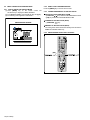
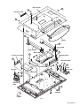
SERVICE MANUAL WIDE LCD PANEL TELEVISION 8 2005 YA232 VCR TV DVD LT-30E45SU, LT-30E45SJ, LT-30E45SU/Z, LT-30E45SU/N MENU BACK P PC TV TABLE OF CONTENTS 1 2 3 4 5 PRECAUTION. . . . . . . . . . . . . . . . . . . . . . . . . . . . . . . . . . . . . . . . . . . . . . . . . . . . . . . . . . . . . . . . . . . . . . . . . 1-3 SPECIFIC SERVICE INSTRUCTIONS . . . . . . . . . . . . . . . . . . . . . . . . . . . . . . . . . . . . . . . . . . . . . . . . . . . . . . 1-6 DISASSEMBLY . . . . . . . . . . . . . . . . . . . . . . . . . . . . . . . . . . . . . . . . . . . . . . . . . . . . . . . . . . . . . . . . . . . . . . 1-10 ADJUSTMENT . . . . . . . . . . . . . . . . . . . . . . . . . . . . . . . . . . . . . . . . . . . . . . . . . . . . . . . . . . . . . . . . . . . . . . . 1-16 TROUBLESHOOTING . . . . . . . . . . . . . . . . . . . . . . . . . . . . . . . . . . . . . . . . . . . . . . . . . . . . . . . . . . . . . . . . . 1-16 COPYRIGHT © 2005 Victor Company of Japan, Limited No.YA232 2005/8 SPECIFICATION Items Contents Dimensions ( W × H × D ) 84.7cm × 52.2cm × 26.0cm [Included stand] 84.7cm × 49.0cm × 10.2cm [TV only] Mass 14.8kg [Included stand] 13.0kg [TV only] Power Input AC100 to AC240 V, 50 Hz Power Consumption 150W (Standby: 4.0W) TV RF System CCIR B/G, I, D/K, L Colour System PAL / SECAM / NTSC 3.58 / NTSC 4.43 (NTSC: EXT only). Stereo System A2 (B/G, D/K), NICAM (B/G, I, D/K, L) Teletext System FLOF (Fastext), TOP, WST (World Standard System) Receiving Frequency VHF 47MHz to 470MHz UHF 470MHz to 862MHz CATV 116MHz to 172MHz / 220MHz to 469MHz Intermediate Frequency VIF 38.9MHz(B/G, D/K, I) SIF 33.4MHz(5.5MHz:B/G) / 32.9MHz(6.0MHz:I) / 32.4MHz(6.5MHz:L,D/K) Colour Sub Carrier Frequency PAL 4.43MHz SECAM 4.40625MHz / 4.25MHz NTSC 3.58MHz / 4.43MHz LCD panel 30V-inch wide aspect (15:9) Screen Size Diagonal : 51.1cm (H:64.3cm × V : 38.6cm) Display Pixels Horizontal : 1280 dots × Vertical : 768 dots (WXGA) Audio Power Output 8W + 8W(10% THD) Speaker 5.0cm, round type × 2 Aerial terminal (VHF/UHF) F-type connector, 75Ω unbalanced, coaxial EXT-1 / EXT-2 (Input / Output) 21-pin Euro connector (SCART socket ) × 2 EXT-3(Input) EXT-4 (Input) Component Video RCA pin jack × 3 625p / 525p / 625i / 525i Y : 1V (p-p), Positive (Negative sync provided), 75 Ω Cb/Cr : 0.7V(p-p), 75 Ω Audio 500mV(rms) (-4dBs), high impedance, RCA pin jack × 2 S-Video Mini-DIN 4 pin × 1 Y: 1V (p-p), Positive (Negative sync provided), 75 Ω C: 0.286V (p-p) (Burst signal), 75 Ω Video 1V (p-p), Positive (Negative sync provided), 75 Ω, RCA pin jack × 1 Audio 500mV (rms), High impedance, RCA pin jack × 2 PC (RGB) Input D-sub 15pin × 1 R/G/B : 0.7V (p-p), 75Ω HD / VD : 1V (p-p) to 5V (p-p), high impedance < Available signal > VGA : 640 pixels × 480 pixels (Horizontal : 31.5kHz / Vertical : 60Hz) XGA : 1024 pixels × 768 pixels (Horizontal : 48.4kHz / Vertical : 60Hz) PC AUDIO input 3.5mm stereo mini jack × 1 Audio output 500mV (rms), Low impedance, RCA pin jack × 2 Subwoofer output More than 0 to 1000mV (rms) (+2.2dBs), low impedance (80Hz when modulated 100%), RCA pin jack × 1 Headphone 3.5mm stereo mini jack × 1 Remote Control Unit RM-C1860 (AA/R6 dry cell battery × 2) Design & specifications are subject to change without notice. 1-2 (No.YA232) SECTION 1 PRECAUTION 1.1 SAFETY PRECAUTIONS (1) The design of this product contains special hardware, many circuits and components specially for safety purposes. For continued protection, no changes should be made to the original design unless authorized in writing by the manufacturer. Replacement parts must be identical to those used in the original circuits. Service should be performed by qualified personnel only. (2) Alterations of the design or circuitry of the products should not be made. Any design alterations or additions will void the manufacturer's warranty and will further relieve the manufacturer of responsibility for personal injury or property damage resulting therefrom. (3) Many electrical and mechanical parts in the products have special safety-related characteristics. These characteristics are often not evident from visual inspection nor can the protection afforded by them necessarily be obtained by using replacement components rated for higher voltage, wattage, etc. Replacement parts which have these special safety characteristics are identified in the parts list of Service manual. Electrical components having such features are identified by shading on the schematics and by ( ) on the parts list in Service manual. The use of a substitute replacement which does not have the same safety characteristics as the recommended replacement part shown in the parts list of Service manual may cause shock, fire, or other hazards. (4) Don't short between the LIVE side ground and ISOLATED (NEUTRAL) side ground or EARTH side ground when repairing. Some model's power circuit is partly different in the GND. The difference of the GND is shown by the LIVE : ( ) side GND, the ISOLATED (NEUTRAL) : ( ) side GND and EARTH : ( ) side GND. Don't short between the LIVE side GND and ISOLATED (NEUTRAL) side GND or EARTH side GND and never measure the LIVE side GND and ISOLATED (NEUTRAL) side GND or EARTH side GND at the same time with a measuring apparatus (oscilloscope etc.). If above note will not be kept, a fuse or any parts will be broken. (5) When service is required, observe the original lead dress. Extra precaution should be given to assure correct lead dress in the high voltage circuit area. Where a short circuit has occurred, those components that indicate evidence of overheating should be replaced. Always use the manufacturer's replacement components. (6) Isolation Check (Safety for Electrical Shock Hazard) After re-assembling the product, always perform an isolation check on the exposed metal parts of the cabinet (antenna terminals, video/audio input and output terminals, Control knobs, metal cabinet, screw heads, earphone jack, control shafts, etc.) to be sure the product is safe to operate without danger of electrical shock. a) Dielectric Strength Test The isolation between the AC primary circuit and all metal parts exposed to the user, particularly any exposed metal part having a return path to the chassis should withstand a voltage of 3000V AC (r.m.s.) for a period of one second. (. . . . Withstand a voltage of 1100V AC (r.m.s.) to an appliance rated up to 120V, and 3000V AC (r.m.s.) to an appliance rated 200V or more, for a period of one second.) This method of test requires a test equipment not generally found in the service trade. b) Leakage Current Check Plug the AC line cord directly into the AC outlet (do not use a line isolation transformer during this check.). Using a "Leakage Current Tester", measure the leakage current from each exposed metal part of the cabinet, particularly any exposed metal part having a return path to the chassis, to a known good earth ground (water pipe, etc.). Any leakage current must not exceed 0.5mA AC (r.m.s.). However, in tropical area, this must not exceed 0.2mA AC (r.m.s.). Alternate Check Method Plug the AC line cord directly into the AC outlet (do not use a line isolation transformer during this check.). Use an AC voltmeter having 1000Ω per volt or more sensitivity in the following manner. Connect a 1500Ω 10W resistor paralleled by a 0.15µF AC-type capacitor between an exposed metal part and a known good earth ground (water pipe, etc.). Measure the AC voltage across the resistor with the AC voltmeter. Move the resistor connection to each exposed metal part, particularly any exposed metal part having a return path to the chassis, and measure the AC voltage across the resistor. Now, reverse the plug in the AC outlet and repeat each measurement. Any voltage measured must not exceed 0.75V AC (r.m.s.). This corresponds to 0.5mA AC (r.m.s.). However, in tropical area, this must not exceed 0.3V AC (r.m.s.). This corresponds to 0.2mA AC (r.m.s.). AC VOLTMETER (HAVING 1000 /V, OR MORE SENSITIVITY) 0.15 F AC-TYPE 1500 10W PLACE THIS PROBE ON EACH EXPOSED METAL PART GOOD EARTH GROUND (No.YA232)1-3 1.2 INSTALLATION 1.2.1 HEAT DISSIPATION If the heat dissipation vent behind this unit is blocked, cooling efficiency may deteriorate and temperature inside the unit will rise. The temperature sensor that protects the unit will be activated when internal temperature exceeds the pre-determined level and power will be turned off automatically.Therefore, please make sure pay attention not to block the heat dissipation vent as well as the ventilation outlet behind the unit and ensure that there is room for ventilation around it. 1.2.3 INSTALLATION REQUIREMENTS To ensure safety in an emergency such as an earthquake, and to prevent accidents, ensure that measures are taken to prevent the TV dropping or falling over. Use the supplied screws to firmly attach the supplied hooks (OPTION) to the back of the TV, and use commercially available cord to fix the TV to rigid components such as walls and columns. Wall Ventilation hole Hook The hook for fall prevention(option) It fixes in a band. TV Stand *Diagram differs from actual appearance. 1.2.2 INSTALLATION REQUIREMENTS Ensure that the minimal distance is maintained, as specified below, between the unit with and the surrounding walls, as well as the floor etc.Install the unit on stable flooring or stands.Take precautionary measures to prevent the unit from tipping in order to protect against accidents and earthquakes. 100 mm 100 mm 100 mm 100 mm 50 mm *Diagram differs from actual appearance. 1-4 (No.YA232) *Diagram differs from actual appearance. 1.2.4 NOTES ON HANDLING (1) WHEN TAKING UNIT OUT OF A PACKING CASE When taking the unit out of a packing case, do not grasp the upper part of the unit. If you take the unit out while grasping the upper part, the LCD PANEL may be damaged because of a pressure. Instead of grasping the upper part, put your hands on the lower backside or sides of the unit. (2) AS FOR PRESSING OR TOUCHING A SPEAKER Be careful not to press the opening of the speaker in the lower part of the unit and around them since the decorative sheet on the surface of the openings may be deformed. 1.3 HANDLING LCD PANEL 1.3.1 PRECAUTIONS FOR TRANSPORTATION When transporting the unit, pressure exerted on the internal LCD panel due to improper handling (such as tossing and dropping) may cause damages even when the unit is carefully packed. To prevent accidents from occurring during transportation, pay careful attention before delivery, such as through explaining the handling instructions to transporters. Ensure that the following requirements are met during transportation, as the LCD panel of this unit is made of glass and therefore fragile: (1) USE A SPECIAL PACKING CASE FOR THE LCD PANEL When transporting the LCD panel of the unit, use a special packing case (packing materials). A special packing case is used when a LCD panel is supplied as a service spare part. (2) ATTACH PROTECTION SHEET TO THE FRONT Since the front (display part) of the panel is vulnerable, attach the protection sheet to the front of the LCD panel before transportation. Protection sheet is used when a LCD panel is supplied as a service spare part. (3) AVOID VIBRATIONS AND IMPACTS The unit may be broken if it is toppled sideways even when properly packed. Continuous vibration may shift the gap of the panel, and the unit may not be able to display images properly. Ensure that the unit is carried by at least 2 persons and pay careful attention not to exert any vibration or impact on it. (4) DO NOT PLACE EQUIPMENT HORIZONTALLY Ensure that it is placed upright and not horizontally during transportation and storage as the LCD panel is very vulnerable to lateral impacts and may break. During transportation, ensure that the unit is loaded along the traveling direction of the vehicle, and avoid stacking them on one another. For storage, ensure that they are stacked in 2 layers or less even when placed upright. 1.3.2 OPTICAL FILTER (ON THE FRONT OF THE LCD PANEL) (1) Avoid placing the unit under direct sunlight over a prolonged period of time. This may cause the optical filter to deteriorate in quality and COLOUR. (2) Clean the filter surface by wiping it softly and lightly with a soft and lightly fuzz cloth (such as outing flannel). (3) Do not use solvents such as benzene or thinner to wipe the filter surface. This may cause the filter to deteriorate in quality or the coating on the surface to come off. When cleaning the filter, usually use the neutral detergent diluted with water. When cleaning the dirty filter, use water-diluted ethanol. (4) Since the filter surface is fragile, do not scratch or hit it with hard materials. Be careful enough not to touch the front surface, especially when taking the unit out of the packing case or during transportation. 1.3.3 PRECAUTIONS FOR REPLACEMENT OF EXTERIOR PARTS Take note of the following when replacing exterior parts (REAR COVER, FRONT PANEL, etc.): (1) Do not exert pressure on the front of the LCD panel (filter surface). It may cause irregular COLOUR. (2) Pay careful attention not to scratch or stain the front of the LCD panel (filter surface) with hands. (3) When replacing exterior parts, the front (LCD panel) should be placed facing downward. Place a mat, etc. underneath to avoid causing scratches to the front (filter surface). (No.YA232)1-5 SECTION 2 SPECIFIC SERVICE INSTRUCTIONS 2.1 FEATURES T-V LINK When you have a T-V LINK compatible VCR connected to the EXT-2 Terminal on the TV,it is easier to set up the VCR and to view videos. ZOOM This function can change the screen size according to the picture aspect ratio. 2.2 OFF TIMER This function can set the TV to automatically turn off after a set time. COLOUR SYSTEM If the picture is not clear or no colour appears, change the current colour system to another colour system. MAIN DIFFERENCE LIST Items LT-30E45SU LT-30E45SJ LT-30E45SU/Z LT-30E45SU/N POWER CORD EU type(2-pin) UK type(3-pin) SWE Type(3-pin) EU type(2-pin) AV JACK PWB VE-20185947 ← ← VE-20148274 2.3 21-PIN EURO CONNECTOR (SCART) : EXT-1 / EXT-2 Pin No. Signal designation Matching value 500mV(rms) (Nominal),, Low impedance EXT-1 Used (TV OUT) EXT-2 1 AUDIO R output Used (LINE OUT) 2 AUDIO R input 500mV(rms) (Nominal),, High impedance Used (R1) Used (R2) 3 AUDIO L output 500mV(rms) (Nominal),, Low impedance Used (TV OUT) Used (LINE OUT) 4 AUDIO GND Used Used 5 GND (B) Used Used 6 AUDIO L input 500mV(rms) (Nominal),, High impedance Used (L1) Used (L2) 7 B input 700mV(B-W), 75Ω Used Used 8 FUNCTION SW (SLOW SW) Low : 0V-3V High : 8V-12V, High impedance Used Used Used 9 GND (G) Used 10 SCL / T-V LINK Not used Used (SCL2 / TV-LINK) 11 G input Used Used 12 SDA Not used Used (SDA2) 13 GND (R) Used Used 14 GND (YS) Used Not used 15 R / C input R : 700mV(B-W), 75Ω C : 300mV(P-P), 75Ω Used (R) Used (C2/R) 16 Ys input (FAST SW) Low : 0V-0.4V, High : 1V-3V, 75Ω 17 GND (VIDEO output) 700mV(B-W), 75Ω Used Used Used Used Used Used 18 GND (VIDEO input) 19 VIDEO output 1V(P-P) (Negative sync), 75Ω Used (TV OUT) Used (LINE OUT) 20 VIDEO / Y input 1V(P-P) (Negative sync), 75Ω Used Used 21 COMMON GND Used Used (P-P= Peak to Peak, B-W= Blanking to white peak) [Pin assignment] 20 21 1-6 (No.YA232) 18 16 19 17 14 15 12 13 11 10 8 9 6 7 4 5 2 3 1 2.4 TECHNICAL INFORMATION 2.4.1 LCD PANEL This unit uses the flat type panel LCD (Liquid Crystal Display) panel that occupies as little space as possible, instead of the conventional CRT (Cathode Ray Tube), as a display unit. Since the unit has the two polarizing filter that are at right angles to each other, the unit adopts "normally black" mode, where light does not pass through the polarizing filter and the screen is black when no voltage is applied to the liquid crystals. 2.4.1.1 SPECIFICATIONS The following table shows the specifications of this unit. Item Specifications Displayed colour 16777216 colours Brightness 500cd/m2 Contrast ratio 600: 1 Response time 15ms View angle Horizontally: 170°, Vertically: 170° Remarks 256 colours for R, G, and B 2.4.1.2 PIXEL FAULT There are three pixel faults - bright fault , dark fault and flicker fault - that are respectively defined as follows. BRIGHT FAULT In this pixel fault, a cell that should not light originally is lighting on and off. For checking this pixel fault, input ALL BLACK SCREEN and find out the cell that is lighting on and off. DARK FAULT In this pixel fault, a cell that should light originally is not lighting or lighting with the brightness twice as brighter as originally lighting. For checking this pixel fault, input 100% of each R/G/B colour and find out the cell that is not lighting. FLICKER FAULT In the pixel fault, a cell that should light originally or not light originally is flashing on and off. For checking this pixel fault, input ALL BLACK SCREEN signal or 100% of each RGB colour and find out the cell that is flashing on and off. (No.YA232)1-7 2.5 BASIC OPERATION OF SERVICE MODE 2.5.1 HOW TO ENTER THE SERVICE MODE (1) Press [MENU] key on the remote control unit simultaneously to display the MENU SCREEN. (2) In the MENU SCREEN, press the [4] ,[7] ,[2] and [5] key. (3) The following menu appears on the screen. SERVICE MODE SCREEN 2.5.2 HOW TO EXIT THE SERVICE MODE Press the [MENU] key to exit the Service mode. 2.5.3 CHANGE AND MEMORY OF SETTING VALUE SELECTION OF SETTING MENU & ITEM • [FUNCTION /] key: Select the SETTING MENU & ITEM • [OK] key: Decision the SETTING MENU & ITEM CHANGE OF SETTING VALUE (DATA) • [FUNCTION /] key. MEMORY OF SETTING VALUE (DATA) The setting value will be stored automatically when release the REMOTE CONTROL UNIT keys 2.5.4 SERVICE MODE SELECT KEY LOCATION [ 1-8 (No.YA232) [OK] ] [ ] 2.5.5 SERVICE MODE SETTING ITEMS Setting menu display calibration deinterlacer Setting items Variable range Setting value blank color brack / red / green / blue black scart prescale 0 - 127 14 nicam prescale 0 - 127 35 fm/am prescale 0 - 127 16 subwoofer corner 0-7 5 subwoofer level 0 - 32 32 agc 0 - 31 16 color temperature 5500K / 6500K / 7500K / 9300K / user 5500K color temperature-user 5500K / 6500K / 7500K / 9300K 5500K video format auto / ntsc / pal / secam / ntsc auto color space RGB / YPbPr SMPTE240 / YPbPr REC709 / YCbCr REC601 RGB test pattern none / solid color / vert bars. none color components all / red / green / blue. all solid field level 0 - 64 33 initial aps on / off on black expansion on / off dcti 0 - 255 dlti 0 - 255 These values are notrecorded for this reasonthey are adjusted to aspecified value. luminance peaking on / off film mode on / off film mode speed 0/1/2/3 vof on / off bad cut on / off nr threshold low / high noise reduction 0 - 255 lai level 0/1/2 sharpness 0 - 255 sparkle 0 - 255 (No.YA232)1-9 SECTION 3 DISASSEMBLY 3.1 DISASSEMBLY PROCEDURE NOTE: • Make sure that the power cord is disconnected from the outlet. • Pay special attention not to break or damage the parts. • When removing each board, remove the connectors as required. Taking notes of the connecting points (connector numbers) makes service procedure manageable. • Make sure that there is no bent or stain on the connectors before inserting, and firmly insert the connectors. 3.1.1 REMOVING THE STAND (Fig.1) (1) Remove the 4 screws [A], then remove the STAND. 3.1.2 REMOVING THE REAR COVER (Fig.1) • Remove the STAND. (1) Remove the 12 screws [B] and 4 screws [C], then remove the REAR COVER. 3.1.3 REMOVING THE MAIN PWB (Fig.1) • Remove the STAND. • Remove the REAR COVER. (1) Remove the 4 screws [D], then remove the RIGHT FRAME. (2) Remove the 4 screws [E], then remove the LEFT FRAME. (3) Remove the 2 screws [W], then remove the TERMINAL BASE. (4) Remove the 8 screws [F] and 2 screws [G], then remove the MAIN PWB. 3.1.4 REMOVING THE POWER PWB (Fig.1) • Remove the STAND. • Remove the REAR COVER. (1) Remove the 4 screws [H], then remove the POWER PWB. 3.1.5 REMOVING THE POWER UNIT (Fig.1) • Remove the STAND. • Remove the REAR COVER. (1) Remove the 4 screws [J], then remove the POWER UNIT. 3.1.6 REMOVING THE CONTROL BOTTON PWB (Fig.1) • Remove the STAND. • Remove the REAR COVER. (1) Remove the 3 screws [K], then remove the CONTROL BOTTON PWB. 1-10 (No.YA232) 3.1.7 REMOVING THE FAV PWB (Fig.1) • Remove the STAND. • Remove the REAR COVER. (1) Remove the 2 screws [L], then remove the CONTROL BASE with FAV PWB. (2) Remove the 2 screws [M], then remove the FAV PWB from the CONTROL BASE. 3.1.8 REMOVING THE AMPLIFIRE PWB (Fig.1) • Remove the STAND. • Remove the REAR COVER. (1) Remove the 4 screws [N], then remove the AMPLIFIRE PWB. 3.1.9 REMOVING THE NOISE FILTER PWB (Fig.1) • Remove the STAND. • Remove the REAR COVER. (1) Remove the 3 screws [P], 2 screws [R] and 1 screw [Q], then remove the NOISE FILTER PWB. 3.1.10 REMOVING THE LED PWB (Fig.1) • Remove the STAND. • Remove the REAR COVER. (1) Remove the 2 screws [T], then remove the LED PWB. REAR COVER A C CONTROL KNOB B D STAND E LEFT FRAME G RIGHT FRAME CONTROL BUTTON PWB K H W MAIN PWB TERMINAL BASE F J AMPLIFIER PWB N P Q POWER PWB NOISE FILTER PWB FAV PWB M R POWER UNIT L CONTROL BASE T LED PWB FRONT Fig.1 (No.YA232)1-11 3.1.11 REMOVING THE SPEAKER (Fig.2) • Remove the STAND. • Remove the REAR COVER. (1) Remove the 4 screws [A], then remove the SPEAKER with SPEAKER BASE. (2) Remove the 4 screws [B], then remove the SUB SPEAKER (L/R). (3) Remove the 8 screws [C], then remove the SPEAKER from the SPEAKER BASE. 3.1.12 REMOVING THE LCD PANEL UNIT (Fig.2) • Remove the STAND. • Remove the REAR COVER. (1) Remove the 4 screws [D] and the 12 screws [E], then remove the LCD PANEL UNIT with the MAIN BASE. (2) Remove the 4 screws [F], then remove the MAIN BASE from the LCD PANEL UNIT. NOTE: • Pay special attention not to break or damage on the LCD PANEL face or frame. • The LCD PANEL UNIT is fixed to the FRONT COVER (at the back side) by using double-side adhesive tapes. To remove the LCD PANEL UNIT, remove the adhesive tape on the FRONT PANELslowly. 1-12 (No.YA232) F E F MAIN BASE LCD PANEL UNIT D D SUB SPEAKER (L) C C A B A SPEAKER (L) SPEAKER (R) SPEAKER BASE B SUB SPEAKER (R) SPEAKER BASE FRONT PANEL FRONT Fig.2 (No.YA232)1-13 3.2 MEMORY IC REPLACEMENT • This model uses the memory IC. • This memory IC stores data for proper operation of the video and drive circuits. • When replacing, be sure to use an IC containing this (initial value) data. 3.2.1 SETTINGS OF FACTORY SHIPMENT 3.2.1.1 BUTTON OPERATION Setting item Off VOLUME 21 TV/AV TV REMOTE CONTROL DIRECT OPERATION Setting item Setting position POWER 3.2.1.3 3.2.1.2 ZOOM Setting position AUTO REMOTE CONTROL MENU OPERATION (4) OPTIONS (1) PICTURE Setting item brightness Setting position Setting item Setting position 61 language Contrast 36 vcr OFF Sharpness 50 osd timeout 15 Color 43 menu background Translucent tint 50 child lock OFF phase (PC signal input only) 50 scart 2 out Scart 1 sleep timer 0 (2) WINDOW Setting item image size TV/EXT PC pip size (pip selected only) Setting position Auto Fill all 10 pip position (pip selected only) upper left posision h position (PC signal input only) 10 v position (PC signal input only) 21 (3) AUDIO Setting item Setting position volume 21 hp volume 19 hp sound mode Autodetected balance 0 equalizer 120Hz flat 500Hz flat 1.5kHz flat 5kHz flat 10kHz flat hyper sound OFF Dynamic bass OFF 1-14 (No.YA232) english 3.3 REPLACEMENT OF CHIP COMPONENT 3.3.1 CAUTIONS (1) Avoid heating for more than 3 seconds. (2) Do not rub the electrodes and the resist parts of the pattern. (3) When removing a chip part, melt the solder adequately. (4) Do not reuse a chip part after removing it. 3.3.2 SOLDERING IRON (1) Use a high insulation soldering iron with a thin pointed end of it. (2) A 30w soldering iron is recommended for easily removing parts. 3.3.3 REPLACEMENT STEPS 1. How to remove Chip parts 2. How to install Chip parts [Resistors, capacitors, etc.] [Resistors, capacitors, etc.] (1) As shown in the figure, push the part with tweezers and alternately melt the solder at each end. (1) Apply solder to the pattern as indicated in the figure. (2) Grasp the chip part with tweezers and place it on the solder. Then heat and melt the solder at both ends of the chip part. (2) Shift with the tweezers and remove the chip part. [Transistors, diodes, variable resistors, etc.] [Transistors, diodes, variable resistors, etc.] (1) Apply extra solder to each lead. SOLDER (1) Apply solder to the pattern as indicated in the figure. (2) Grasp the chip part with tweezers and place it on the solder. (3) First solder lead A as indicated in the figure. SOLDER A (2) As shown in the figure, push the part with tweezers and alternately melt the solder at each lead. Shift and remove the chip part. B C (4) Then solder leads B and C. A B NOTE : After removing the part, remove remaining solder from the pattern. C (No.YA232)1-15 SECTION 4 ADJUSTMENT This service manual does not describe ADJUSTMENT. SECTION 5 TROUBLESHOOTING This service manual does not describe TROUBLESHOOTING. 1-16 (No.YA232) Victor Company of Japan, Limited AV & MULTIMEDIA COMPANY DISPLAY CATEGORY 12, 3-chome, Moriya-cho, Kanagawa-ku, Yokohama-city, Kanagawa-prefecture, 221-8528, Japan (No.YA232) Printed in Japan VPT