1
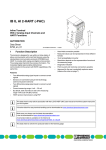
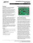
VHF Modbus Receiver User Manual
Version 2.0
1
Table of Contents
1
WEEE & THE BATTERY DIRECTIVE ........................................................................................ 3
2
INTRODUCTION ........................................................................................................................... 4
3
3.1
3.2
INSTALLATION............................................................................................................................. 5
Location ........................................................................................................................................ 5
LED Indication ............................................................................................................................. 5
4
CONNECTIONS ............................................................................................................................. 6
5
CONFIGURATION ......................................................................................................................... 7
5.1 Dip Switch Settings ...................................................................................................................... 7
5.2 Programming ................................................................................................................................ 7
5.3 Addressing Modes ........................................................................................................................ 8
5.3.1 8-Bit Addressing........................................................................................................................... 8
5.3.2 16-Bit Addressing (Extended Addressing Range) ....................................................................... 8
5.4 Code Examples ............................................................................................................................. 9
5.4.1 Code 66 – Program Unit ID ......................................................................................................... 9
5.4.2 Code 03 – Read Holding Registers (8-Bit Addressing) ............................................................... 9
5.4.3 Code 03 – Read Holding Registers (16-Bit Addressing) ............................................................. 9
5.4.4 Code 16 – Write Multiple Register (8-bit Addressing) .............................................................. 10
5.4.5 Code 16 – Write Multiple Register (16-Bit Addressing) ........................................................... 10
6
TRANSMITTER TYPES .............................................................................................................. 11
6.1 Pulse Transmitter – Type 81 ...................................................................................................... 11
6.2 Digital Temperature Transmitter – Type 82............................................................................... 11
6.3 Alarm/Status Transmitter – Type 88 .......................................................................................... 12
APPENDIX 1 ............................................................................................................................................ 13
Memory Map (8-Bit Addressing) ......................................................................................................... 13
Memory Map (16-Bit Addressing) ....................................................................................................... 18
APPENDIX 2 ............................................................................................................................................ 22
Modbus CRC Algorithm ....................................................................................................................... 22
2
1 WEEE & the Battery Directive
Waste Electrical and Electronic Equipment.
HWM-Water Ltd is a registered producer of Electrical and Electronic Equipment in the United Kingdom (registration
number WEE/AE0049TZ). Our products fall under category 9 (Monitoring and Control Instruments) of The Waste Electrical
and Electronic Equipment (WEEE) Regulations. We take all environmental issues seriously and fully comply with the
requirements for collection, recycling and reporting of waste products.
HWM-Water Ltd is responsible for WEEE from customers in the United Kingdom provided that:
The equipment was produced by HWM-Water Ltd (Palmer Environmental/Radcom Technologies/Radiotech/ASL Holdings
Ltd) and supplied on or after 13th August 2005
The equipment was supplied before 13th August 2005 that has been directly replaced HWM-Water Ltd products
manufactured since 13th August 2005.
HWM-Water products supplied after 13th August 2005 can be identified by the following symbol:
Under HWM-Water Ltd Terms and Conditions of Sale, customers are responsible for the cost of returning WEEE to HWMWater Ltd and we are responsible for the costs of recycling and reporting on that waste.
Instructions for returning WEEE:
Ensure that the WEEE meets one of the two conditions above.
The waste will need to be returned in accordance with the regulations for transporting data loggers with lithium batteries.
a. Pack loggers in strong, rigid outer packaging to protect them from damage.
b. Attach a Lithium Warning Label to the package.
c. The package must be accompanied by a document (e.g. consignment note) that indicates:
i. The package contains lithium metal cells;
ii. The package must be handled with care and that a flammability hazard exists if the package is damaged;
iii. Special procedures should be followed in the event the package is damaged, to include inspection and
repacking if necessary; and
iiii. A telephone number for additional information.
d. Refer to the ADR regulations on shipping dangerous goods by road.
Return the WEEE to HWM-Water Ltd using a licensed waste carrier.
In accordance with the regulations, customers outside the United Kingdom are responsible for WEEE.
The Battery Directive
As a distributor of batteries HWM-Water Ltd will accept old batteries back from customers for disposal, free of charge, in
accordance with the Battery Directive.
PLEASE NOTE: All lithium batteries MUST be packaged and returned in accordance with the relevant regulations for
transporting lithium batteries.
A licensed waste carrier must be used for transporting all waste.
For more information on WEEE compliance or the Battery Directive please e-mail [email protected] or phone
+44 (0)1633 489 479
If further support or assistance is required, please contact
HWM Technical Support on 01633 489479 (option 5)
or e-mail [email protected]
3
2 Introduction
The VHF Modbus receiver has been designed to provide a complete solution for fixed data collection. It
is designed to work in conjunction with most of the AMR range of VHF transmitters. The receiver
decodes the data, verifies using a 16-bit CRC check (Appendix 2) and passes the data packet through to
the serial port.
Receiver Frequency:
Modbus Mode:
Number of Devices Supported:
Communications Protocol:
Communications Setup:
Functions Codes Supported:
153.10MHz or 169.40625MHz.
Modbus Slave Remote Terminal Unit (RTU) supported.
Slave address configurable.
32
RS232 & RS485
4800, No Parity, 8-bits, 1-Stop or 9600, No Parity, 8-bits,1-Stop
•
•
•
0x03 (03 dec) Read Holding Registers
0x10 (16dec) Write Multiple Registers
0x42 (66 dec) Special Function Code
Operating Environment:
Operating Temperature Range: -10°C to +40°C (Recommended for indoor use only).
Dimensions: 98 x 198 x 82mm (approx.) excluding connectors and glands.
Protection Rating: IP65 (when sealed).
Power Supply:
Operating Voltage: 12VDC from plug top power supply.
Enclosure:
Die-cast Aluminium – painted grey.
4
3 Installation
As with any radio communication system, the Modbus receiver should be connected to a clean and
stable power supply. Both AC and DC power supplies can be used to power the receiver.
If using a switch mode power supply, be aware these types can be rich in harmonics that can cause the
high gain receiver module to block the reception of data. The frequency of offending harmonics can
shift with temperature, time and load.
For maximum transmission range the antenna of both the transmitter and receiver should point upward
(vertical polarization) and should be kept clear of obstructions, particularly metallic surfaces.
As standard, an N-type helical antenna is supplied with the Modbus receiver, should an alternative be
required contact the HWM Sales department for alternatives. Whatever antenna type is selected ensure
the impedance is 50Ω.
3.1 Location
For indoor installations, it is recommended that the receiver is located away from sources of heat and
electrical apparatus such as inverters. Care should be taken to minimise cable lengths both with respect
to the antenna location and the attached terminal equipment. Generally, RS232 should be used for short
distance links <10m and RS485 for longer links <300m.
3.2 LED Indication
A number of visual indicators are present on the PCB to provide some level of diagnostics.
DC Power:
TxD LED:
RxD. LED:
ON (Green) – Receiver has power
ON (Red) – Sending data on communications port
ON (Amber) – Receiving data
5
4 Connections
Data and power connections should always be made using screened cable. Using a screened cable will
help to reject interference. You should always use a common ground point and avoid the formation of
current loops.
Terminal
Screen
0V
+12V
TX(DATA)
RX(DATA)
B/Z (-)
A/Y (+)
+5V (OUT)
Description
Earth (Comms Cable Screen)
DC Power –ve
DC Positive +ve
RS232 Tx Output
RS232 RX Input
BZ - RS485 +ve
AY - RS485 –ve
+5V Out
Notes
Can be used as pull-up for RS485 bus
Note: RS485 connections, it is the responsibility of the system builder to ensure that the connections
are correctly terminated. Normally, cables with an impedance of greater than 100Ω should be used.
Open ends may need terminating using 120Ω resistors between the AY and BZ terminals.
6
5 Configuration
5.1 Dip Switch Settings
SW1 – Receiver outputs Binary data
SW2 – Receiver outputs ASCII data
SW3 – Set data rate to 4800Baud (either SW3 or SW4 ON – do not set both to ON position).
SW4 – Set data rate to 9600Baud (either SW3 or SW4 ON – do not set both to ON position).
Note: Only select SW1 or SW2 to be ON for serial format, similarly with SW3 or SW4 for Baud-rate.
Configuration DIP
Switches.
Default Settings:
SW1 – OFF
SW2 – OFF
SW3 – ON
SW4 – OFF
The communication mode selection jumper should set to either:
Left + Middle of header pins for RS232 mode.
Or Middle + Right of header pins for RS485 mode.
5.2
Programming
A simple programming application is available from HWM to program and validate the receiver.
However, it is strongly recommended that this is built into the system.
The Modbus Receiver supports the Modbus remote terminal unit (RTU) Slave Mode. Only two
standard function codes are supported (03dec & 16dec), an additional custom code (66dec) is used to
program unit ID.
The receiver needs to be programmed with the addresses of all the transmitters expected to receive. A
memory map is defined (Appendix 1) holding the transmitter IDs, status and data bytes. This data can
be read back by the Modbus Master device.
7
5.3
Addressing Modes
5.3.1 8-Bit Addressing
The addresses of the transmitters need to be programmed into the memory map and read back with the
data as verification. E.g. consider transmitter in memory slot 2:
No.
2
2
2
2
2
2
2
2
Reg DEC
792
793
794
795
796
797
798
799
Reg HEX
0318
0319
031A
031B
031C
031D
031E
031F
Description
Transmitter Address HHO
Transmitter Address HO
Transmitter Address LO
Transmitter Status
Data 1
Data 2
Data 3
Data 4
Registers 792-794dec (0x0318) hold the 24-bit transmitter address, so if data needs to be received from
transmitter number 54322dec (00D432hex), the registers will need to be programmed with the value
00D432hex, 00hex into register 0x0318, D4hex into register 0x0319 and 32hex into register 0x031A
5.3.2
16-Bit Addressing (Extended Addressing Range)
No.
2
2
2
2
2
2
Reg DEC
4118
4119
4120
4121
4122
4123
Reg HEX
1016
1017
1018
1019
101A
101B
Description
Transmitter Address Hi 16bits
Transmitter Address Lo 16bits
0 Transmitter Status
0
Data 1
Data 2 Data 3
0
Data 4
Registers 4118 (0x1016) and 4119 (0x1017) hold the 24-bit transmitter address, so if data needs to be
received from transmitter number 76322 (012A22hex), the registers will need to be programmed with the
value 012A22hex, 0001hex into register 0x1016 and 2A22hex into register 0x1017.
When data is received from the transmitter, the rest of the registers will be filled with the data received.
The transmitter status and data values vary in their content types depending on the transmitter type being
received.
Modbus supports 8 to 16-bit formats and many of the values implemented on the AMR transmitters vary
between 8 to 24-bits. The Modbus receiver has an 8-bit and 16-bit Modbus (v8 firmware) standards
implemented.
When using the 8-bit standard every register has the first 8-bits set as 00. E.g.data value 1122867dec
(112233hex) in Modbus communications would be broken up into 3 registers and sent as 0011hex, 0022hex
and 0033hex.
8
5.4
Code Examples
Similarly, the host has to configure the addresses in the same way.
Below are some example messages:
Note: When using 8-bit addressing mode all data is transmitted as an 8-bit value and Modbus reads
registers as 16-bit (2 registers). Therefore the high register is always set as 00.
5.4.1
Code 66 – Program Unit ID
To configure the receiver with unit ID 1001 hex using Modbus address 4
00 42 10 01 04 31 EE - all values are hexadecimal
where 0042 - Global Message Code 66
10 01 -16-bit Receiver Address
04
- Modbus Address (to be programmed into unit)
31 EE - CRC
To configure the receiver unit ID 1010 with a Modbus address 10
00 42 10 10 0A BC 7A - all values are hexadecimal
5.4.2
Code 03 – Read Holding Registers (8-Bit Addressing)
Read Ch1 – Ch8 from Modbus Slave 10
0A 03 03 10 00 40 44 C0 - all values are hexadecimal
where 0A
- Slave Address 10
03
- Modbus Function Code
03 10 - First Register to Read
00 40 - 64 Registers to Read (Appendix 1)
44 C0 - CRC
Read Ch9 – Ch16 from Modbus Slave 10
0A 03 03 50 00 40 45 14 - all values are hexadecimal
Read Ch17 – Ch24 from Modbus Slave 10
0A 03 03 90 00 40 45 28 - all values are hexadecimal
Read Ch25 – Ch32 from Modbus Slave 10
0A 03 03 C8 00 40 C4 FB - all values are hexadecimal
5.4.3
Code 03 – Read Holding Registers (16-Bit Addressing)
Read Ch1 – Ch8 from Modbus Slave 10
0A 03 10 10 00 30 44 C0 - all values are hexadecimal
where 0A
- Slave address 10
03
- Modbus Function Code
10 10 - First Register to Read
00 30 - 48 Registers to read (Appendix 1)
41 A0 - CRC
9
5.4.4
Code 16 – Write Multiple Register (8-bit Addressing)
Write address 51234dec (00C822hex) into Ch1 location and clear all other locations- to Slave 4
04 10 03 10 00 08 10 00 00 00 C8 00 22 00 00 00 00 00 00 00 00 00 00 35 93
where
5.4.5
04
- Slave address 4
10
- Modbus Function Code 16
03 10 - First Register to Write to
00 08 - Number of Registers to Write to
10
- Number of bytes following (16)
00 00 00 C8 00 22
- address written into first 3 registers
00 00 - Register 4
00 00 - Register 5
00 00 - Register 6
00 00 - Register 7
00 00 - Register 8
35 93 - CRC
Code 16 – Write Multiple Register (16-Bit Addressing)
Write address 51234dec (00C822hex) into Ch1 location and clear all other locations- to Slave 4
04 10 10 10 00 05 0C 00 00 C8 22 00 00 00 00 00 00 00 00 35 93
where
04
- Slave address 4
10
- Modbus Function Code 16
10 10 - First Register to Write to
00 05 - Number of Registers to Write to
0C
- Number of Bytes Following (12)
00 00 - Transmitter Address Hi 16 bits
C8 22 - Transmitter Address Lo 16 bits
00 00 - Register 3 (0, Transmitter Status)
00 00 - Register 4 (0,Data 1)
00 00 - Register 5 (Data 2,Data 3)
00 00 - Register 6 (0,Data 4)
35 93 - CRC
10
6 Transmitter Types
The firmware in Modbus receivers manufactured on and after May 2013 will have updated firmware.
The update allows for all data types to be received and 16-bit mapping implemented.
Below is a description of the data packet breakdowns for popular types of transmitter. For a complete
list of transmitter types please contact HWM.
6.1
Pulse Transmitter – Type 81
Transmitter Status
Data 1 – Data 3
Data 4
6.2
Bit 7 set for Low Battery.
Bit 4 is Tamper (if available).
Bits 0-3 is Firmware Revision.
24-bit Pulse Count Value.
For example, Value 234455hex = 2311253dec
Cumulative Counter that increments for each data transmission.
High nibble is signal strength (between 0-10) for VHF transmitters.
Low nibble is incremental counter (between 0-15).
Digital Temperature Transmitter – Type 82
Transmitter Status
Data 1 – Data 2
Bit 7 set for Low Battery.
Bits 0-3 is Firmware Revision.
16-bit Temperature Channel 1.
MSB set if Invalid Temperature.
Temperature Value = value/2.
Value Count Positive if Temperature > 0.
Value Counts in Reverse if Temperature < 0.
0002 1.0°C
0001 0.5°C
0000 0°C
0FFF -0.5°C
0FFE -1.0°C
Example:
8034hex = MSB set - Invalid Temperature
0034hex = 52dec Temperature = 52/2 = 26.0°C
0FC3hex = 4035dec
Temperature = (4096-4035)/2 = -30.5°C
Data 3 :
Not Used – Ignore.
Data 4 :
Cumulative Counter that increments for each data transmission.
HO nibble is signal strength (between 0-10).
LO nibble is incremental counter (between 0-15).
11
6.3
Alarm/Status Transmitter – Type 88
Transmitter Status
Data 1 – Data 3
Data 4
Bit 7 set for Low Battery.
Bit 5 is Contact Status Ch2.
Bit 4 is Contact Status Ch1.
Bits 0-3 is Firmware Revision.
24-bit pulse count value.
For example, value 234455hex = 2311253dec
Cumulative Counter that increments for each data transmission.
High nibble is signal strength (between 0-10) for VHF transmitters.
Low nibble is incremental counter (between 0-15).
12
Appendix 1
Memory Map (8-Bit Addressing)
Tx.
No.
1
1
1
1
1
1
1
1
2
2
2
2
2
2
2
2
3
3
3
3
3
3
3
3
4
4
4
4
4
4
4
4
5
5
5
5
5
5
5
5
6
6
6
6
6
6
Modbus Register
Address
Dec
Hex
784
785
786
787
788
789
790
791
792
793
794
795
796
797
798
799
800
801
802
803
804
805
806
807
808
809
810
811
812
813
814
815
816
817
818
819
820
821
822
823
824
825
826
827
828
829
0310
0311
0312
0313
0314
0315
0316
0317
0318
0319
031A
031B
031C
031D
031E
031F
0320
0321
0322
0323
0324
0325
0326
0327
0328
0329
032A
032B
032C
032D
032E
032F
0330
0331
0332
0333
0334
0335
0336
0337
0338
0339
033A
033B
033C
033D
Description
Transmitter Address HHO
Transmitter Address HO
Transmitter Address LO
Transmitter Status
Data 1
Data 2
Data 3
Data4
Transmitter Address HHO
Transmitter Address HO
Transmitter Address LO
Transmitter Status
Data 1
Data 2
Data 3
Data 4
Transmitter Address HHO
Transmitter Address HO
Transmitter Address LO
Transmitter Status
Data 1
Data 2
Data 3
Data4
Transmitter Address HHO
Transmitter Address HO
Transmitter Address LO
Transmitter Status
Data 1
Data 2
Data 3
Data 4
Transmitter Address HHO
Transmitter Address HO
Transmitter Address LO
Transmitter Status
Data 1
Data 2
Data 3
Data4
Transmitter Address HHO
Transmitter Address HO
Transmitter Address LO
Transmitter Status
Data 1
Data 2
13
6
6
7
7
7
7
7
7
7
7
8
8
8
8
8
8
8
8
9
9
9
9
9
9
9
9
10
10
10
10
10
10
10
10
11
11
11
11
11
11
11
11
12
12
12
12
12
12
12
12
13
13
13
13
13
13
830
831
832
833
834
835
836
837
838
839
840
841
842
843
844
845
846
847
848
849
850
851
852
853
854
855
856
857
858
859
860
861
862
863
864
865
866
867
868
869
870
871
872
873
874
875
876
877
878
879
880
881
882
883
884
885
033E
033F
0340
0341
0342
0343
0344
0345
0346
0347
0348
0349
034A
034B
034C
034D
034E
034F
0350
0351
0352
0353
0354
0355
0356
0357
0358
0359
035A
035B
035C
035D
035E
035F
0360
0361
0362
0363
0364
0365
0366
0367
0368
0369
036A
036B
036C
036D
036E
036F
0370
0371
0372
0373
0374
0375
Data 3
Data 4
Transmitter Address HHO
Transmitter Address HO
Transmitter Address LO
Transmitter Status
Data 1
Data 2
Data 3
Data4
Transmitter Address HHO
Transmitter Address HO
Transmitter Address LO
Transmitter Status
Data 1
Data 2
Data 3
Data 4
Transmitter Address HHO
Transmitter Address HO
Transmitter Address LO
Transmitter Status
Data 1
Data 2
Data 3
Data4
Transmitter Address HHO
Transmitter Address HO
Transmitter Address LO
Transmitter Status
Data 1
Data 2
Data 3
Data 4
Transmitter Address HHO
Transmitter Address HO
Transmitter Address LO
Transmitter Status
Data 1
Data 2
Data 3
Data4
Transmitter Address HHO
Transmitter Address HO
Transmitter Address LO
Transmitter Status
Data 1
Data 2
Data 3
Data 4
Transmitter Address HHO
Transmitter Address HO
Transmitter Address LO
Transmitter Status
Data 1
Data 2
14
13
13
14
14
14
14
14
14
14
14
15
15
15
15
15
15
15
15
16
16
16
16
16
16
16
16
17
17
17
17
17
17
17
17
18
18
18
18
18
18
18
18
19
19
19
19
19
19
19
19
20
20
20
20
20
20
886
887
888
889
890
891
892
893
894
895
896
897
898
899
900
901
902
903
904
905
906
907
908
909
910
911
912
913
914
915
916
917
918
919
920
921
922
923
924
925
926
927
928
929
930
931
932
933
934
935
936
937
938
939
940
941
0376
0377
0378
0379
037A
037B
037C
037D
037E
037F
0380
0381
0382
0383
0384
0385
0386
0387
0388
0389
038A
038B
038C
038D
038E
038F
0390
0391
0392
0393
0394
0395
0396
0397
0398
0399
039A
039B
039C
039D
039E
039F
03A0
03A1
03A2
03A3
03A4
03A5
03A6
03A7
03A8
03A9
03AA
03AB
03AC
03AD
Data 3
Data4
Transmitter Address HHO
Transmitter Address HO
Transmitter Address LO
Transmitter Status
Data 1
Data 2
Data 3
Data 4
Transmitter Address HHO
Transmitter Address HO
Transmitter Address LO
Transmitter Status
Data 1
Data 2
Data 3
Data4
Transmitter Address HHO
Transmitter Address HO
Transmitter Address LO
Transmitter Status
Data 1
Data 2
Data 3
Data 4
Transmitter Address HHO
Transmitter Address HO
Transmitter Address LO
Transmitter Status
Data 1
Data 2
Data 3
Data4
Transmitter Address HHO
Transmitter Address HO
Transmitter Address LO
Transmitter Status
Data 1
Data 2
Data 3
Data 4
Transmitter Address HHO
Transmitter Address HO
Transmitter Address LO
Transmitter Status
Data 1
Data 2
Data 3
Data4
Transmitter Address HHO
Transmitter Address HO
Transmitter Address LO
Transmitter Status
Data 1
Data 2
15
20
20
21
21
21
21
21
21
21
21
22
22
22
22
22
22
22
22
23
23
23
23
23
23
23
23
24
24
24
24
24
24
24
24
25
25
25
25
25
25
25
25
26
26
26
26
26
26
26
26
27
27
27
27
27
27
942
943
944
945
946
947
948
949
950
951
952
953
954
955
956
957
958
959
960
961
962
963
964
965
966
967
968
969
970
971
972
973
974
975
976
977
978
979
980
981
982
983
984
985
986
987
988
989
990
991
992
993
994
995
996
997
03AE
03AF
03B0
03B1
03B2
03B3
03B4
03B5
03B6
03B7
03B8
03B9
03BA
03BB
03BC
03BD
03BE
03BF
03C0
03C1
03C2
03C3
03C4
03C5
03C6
03C7
03C8
03C9
03CA
03CB
03CC
03CD
03CE
03CF
03D0
03D1
03D2
03D3
03D4
03D5
03D6
03D7
03D8
03D9
03DA
03DB
03DC
03DD
03DE
03DF
03E0
03E1
03E2
03E3
03E4
03E5
Data 3
Data 4
Transmitter Address HHO
Transmitter Address HO
Transmitter Address LO
Transmitter Status
Data 1
Data 2
Data 3
Data4
Transmitter Address HHO
Transmitter Address HO
Transmitter Address LO
Transmitter Status
Data 1
Data 2
Data 3
Data 4
Transmitter Address HHO
Transmitter Address HO
Transmitter Address LO
Transmitter Status
Data 1
Data 2
Data 3
Data4
Transmitter Address HHO
Transmitter Address HO
Transmitter Address LO
Transmitter Status
Data 1
Data 2
Data 3
Data 4
Transmitter Address HHO
Transmitter Address HO
Transmitter Address LO
Transmitter Status
Data 1
Data 2
Data 3
Data4
Transmitter Address HHO
Transmitter Address HO
Transmitter Address LO
Transmitter Status
Data 1
Data 2
Data 3
Data 4
Transmitter Address HHO
Transmitter Address HO
Transmitter Address LO
Transmitter Status
Data 1
Data 2
16
27
27
28
28
28
28
28
28
28
28
29
29
29
29
29
29
29
29
30
30
30
30
30
30
30
30
31
31
31
31
31
31
31
31
32
32
32
32
32
32
32
32
998
999
1000
1001
1002
1003
1004
1005
1006
1007
1008
1009
1010
1011
1012
1013
1014
1015
1016
1017
1018
1019
1020
1021
1022
1023
1024
1025
1026
1027
1028
1029
1030
1031
1032
1033
1034
1035
1036
1037
1038
1039
03E6
03E7
03E8
03E9
03EA
03EB
03EC
03ED
03EE
03EF
03F0
03F1
03F2
03F3
03F4
03F5
03F6
03F7
03F8
03F9
03FA
03FB
03FC
03FD
03FE
03FF
0400
0401
0402
0403
0404
0405
0406
0407
0408
0409
040A
040B
040C
040D
040E
040F
Data 3
Data4
Transmitter Address HHO
Transmitter Address HO
Transmitter Address LO
Transmitter Status
Data 1
Data 2
Data 3
Data 4
Transmitter Address HHO
Transmitter Address HO
Transmitter Address LO
Transmitter Status
Data 1
Data 2
Data 3
Data4
Transmitter Address HHO
Transmitter Address HO
Transmitter Address LO
Transmitter Status
Data 1
Data 2
Data 3
Data 4
Transmitter Address HHO
Transmitter Address HO
Transmitter Address LO
Transmitter Status
Data 1
Data 2
Data 3
Data4
Transmitter Address HHO
Transmitter Address HO
Transmitter Address LO
Transmitter Status
Data 1
Data 2
Data 3
Data 4
The transmitter address and data values are 24-bit, Modbus works with 16-bit registers, all the above
registers are sent as 16-bit addresses. The high byte will always be 00, for example: for a pulse count of
34562dec (008702hex), will be sent as 0x0000, 0x0087 & 0x0002 for Data 1, Data 2 and Data 3.
17
Memory Map (16-Bit Addressing)
Note: 16-bit addressing mode is only available on firmware version V8.00 and above. The Following
table details the extended register map used for 16-bit addressing mode.
Tx.
No.
N/A
N/A
N/A
1
1
1
1
1
1
2
2
2
2
2
2
3
3
3
3
3
3
4
4
4
4
4
4
5
5
5
5
5
5
6
6
6
6
6
6
7
7
7
7
7
7
8
Modbus Register
Address
Dec
Hex
4096
4097
4098
4112
4113
4114
4115
4116
4117
4118
4119
4120
4121
4122
4123
4124
4125
4126
4127
4128
4129
4130
4131
4132
4133
4134
4135
4136
4137
4138
4139
4140
4141
4142
4143
4144
4145
4146
4147
4148
4149
4150
4151
4152
4153
4154
1000
1001
1002
1010
1011
1012
1013
1014
1015
1016
1017
1018
1019
101A
101B
101C
101D
101E
101F
1020
1021
1022
1023
1024
1025
1026
1027
1028
1029
102A
102B
102C
102D
102E
102F
1030
1031
1032
1033
1034
1035
1036
1037
1038
1039
103A
Description
High byte
Low byte
Firmware ID
Firmware Version
Frequency band
Transmitter Address Hi 16bits
Transmitter Address Lo 16bits
0
Transmitter Status
0
Data 1
Data 2
Data 3
0
Data 4
Transmitter Address Hi 16bits
Transmitter Address Lo 16bits
0
Transmitter Status
0
Data 1
Data 2
Data 3
0
Data 4
Transmitter Address Hi 16bits
Transmitter Address Lo 16bits
0
Transmitter Status
0
Data 1
Data 2
Data 3
0
Data 4
Transmitter Address Hi 16bits
Transmitter Address Lo 16bits
0
Transmitter Status
0
Data 1
Data 2
Data 3
0
Data 4
Transmitter Address Hi 16bits
Transmitter Address Lo 16bits
0
Transmitter Status
0
Data 1
Data 2
Data 3
0
Data 4
Transmitter Address Hi 16bits
Transmitter Address Lo 16bits
0
Transmitter Status
0
Data 1
Data 2
Data 3
0
Data 4
Transmitter Address Hi 16bits
Transmitter Address Lo 16bits
0
Transmitter Status
0
Data 1
Data 2
Data 3
0
Data 4
Transmitter Address Hi 16bits
18
8
8
8
8
8
9
9
9
9
9
9
10
10
10
10
10
10
11
11
11
11
11
11
12
12
12
12
12
12
13
13
13
13
13
13
14
14
14
14
14
14
15
15
15
15
15
15
16
16
16
16
16
16
17
17
17
4155
4156
4157
4158
4159
4160
4161
4162
4163
4164
4165
4166
4167
4168
4169
4170
4171
4172
4173
4174
4175
4176
4177
4178
4179
4180
4181
4182
4183
4184
4185
4186
4187
4188
4189
4190
4191
4192
4193
4194
4195
4196
4197
4198
4199
4200
4201
4202
4203
4204
4205
4206
4207
4208
4209
4210
103B
103C
103D
103E
103F
1040
1041
1042
1043
1044
1045
1046
1047
1048
1049
104A
104B
104C
104D
104E
104F
1050
1051
1052
1053
1054
1055
1056
1057
1058
1059
105A
105B
105C
105D
105E
105F
1060
1061
1062
1063
1064
1065
1066
1067
1068
1069
106A
106B
106C
106D
106E
106F
1070
1071
1072
Transmitter Address Lo 16bits
0
Transmitter Status
0
Data 1
Data 2
Data 3
0
Data 4
Transmitter Address Hi 16bits
Transmitter Address Lo 16bits
0
Transmitter Status
0
Data 1
Data 2
Data 3
0
Data 4
Transmitter Address Hi 16bits
Transmitter Address Lo 16bits
0
Transmitter Status
0
Data 1
Data 2
Data 3
0
Data 4
Transmitter Address Hi 16bits
Transmitter Address Lo 16bits
0
Transmitter Status
0
Data 1
Data 2
Data 3
0
Data 4
Transmitter Address Hi 16bits
Transmitter Address Lo 16bits
0
Transmitter Status
0
Data 1
Data 2
Data 3
0
Data 4
Transmitter Address Hi 16bits
Transmitter Address Lo 16bits
0
Transmitter Status
0
Data 1
Data 2
Data 3
0
Data 4
Transmitter Address Hi 16bits
Transmitter Address Lo 16bits
0
Transmitter Status
0
Data 1
Data 2
Data 3
0
Data 4
Transmitter Address Hi 16bits
Transmitter Address Lo 16bits
0
Transmitter Status
0
Data 1
Data 2
Data 3
0
Data 4
Transmitter Address Hi 16bits
Transmitter Address Lo 16bits
0
Transmitter Status
0
Data 1
Data 2
Data 3
0
Data 4
Transmitter Address Hi 16bits
Transmitter Address Lo 16bits
0
Transmitter Status
19
17
17
17
18
18
18
18
18
18
19
19
19
19
19
19
20
20
20
20
20
20
21
21
21
21
21
21
22
22
22
22
22
22
23
23
23
23
23
23
24
24
24
24
24
24
25
25
25
25
25
25
26
26
26
26
26
4211
4212
4213
4214
4215
4216
4217
4218
4219
4220
4221
4222
4223
4224
4225
4226
4227
4228
4229
4230
4231
4232
4233
4234
4235
4236
4237
4238
4239
4240
4241
4242
4243
4244
4245
4246
4247
4248
4249
4250
4251
4252
4253
4254
4255
4256
4257
4258
4259
4260
4261
4262
4263
4264
4265
4266
1073
1074
1075
1076
1077
1078
1079
107A
107B
107C
107D
107E
107F
1080
1081
1082
1083
1084
1085
1086
1087
1088
1089
108A
108B
108C
108D
108E
108F
1090
1091
1092
1093
1094
1095
1096
1097
1098
1099
109A
109B
109C
109D
109E
109F
10A0
10A1
10A2
10A3
10A4
10A5
10A6
10A7
10A8
10A9
10AA
0
Data 1
Data 2
Data 3
0
Data 4
Transmitter Address Hi 16bits
Transmitter Address Lo 16bits
0
Transmitter Status
0
Data 1
Data 2
Data 3
0
Data 4
Transmitter Address Hi 16bits
Transmitter Address Lo 16bits
0
Transmitter Status
0
Data 1
Data 2
Data 3
0
Data 4
Transmitter Address Hi 16bits
Transmitter Address Lo 16bits
0
Transmitter Status
0
Data 1
Data 2
Data 3
0
Data 4
Transmitter Address Hi 16bits
Transmitter Address Lo 16bits
0
Transmitter Status
0
Data 1
Data 2
Data 3
0
Data 4
Transmitter Address Hi 16bits
Transmitter Address Lo 16bits
0
Transmitter Status
0
Data 1
Data 2
Data 3
0
Data 4
Transmitter Address Hi 16bits
Transmitter Address Lo 16bits
0
Transmitter Status
0
Data 1
Data 2
Data 3
0
Data 4
Transmitter Address Hi 16bits
Transmitter Address Lo 16bits
0
Transmitter Status
0
Data 1
Data 2
Data 3
0
Data 4
Transmitter Address Hi 16bits
Transmitter Address Lo 16bits
0
Transmitter Status
0
Data 1
Data 2
Data 3
0
Data 4
Transmitter Address Hi 16bits
Transmitter Address Lo 16bits
0
Transmitter Status
0
Data 1
Data 2
Data 3
20
26
27
27
27
27
27
27
28
28
28
28
28
28
29
29
29
29
29
29
30
30
30
30
30
30
31
31
31
31
31
31
32
32
32
32
32
32
4267
4268
4269
4270
4271
4272
4273
4274
4275
4276
4277
4278
4279
4280
4281
4282
4283
4284
4285
4286
4287
4288
4289
4290
4291
4292
4293
4294
4295
4296
4297
4298
4299
4300
4301
4302
4303
10AB
10AC
10AD
10AE
10AF
10B0
10B1
10B2
10B3
10B4
10B5
10B6
10B7
10B8
10B9
10BA
10BB
10BC
10BD
10BE
10BF
10C0
10C1
10C2
10C3
10C4
10C5
10C6
10C7
10C8
10C9
10CA
10CB
10CC
10CD
10CE
10CF
0
Data 4
Transmitter Address Hi 16bits
Transmitter Address Lo 16bits
0
Transmitter Status
0
Data 1
Data 2
Data 3
0
Data 4
Transmitter Address Hi 16bits
Transmitter Address Lo 16bits
0
Transmitter Status
0
Data 1
Data 2
Data 3
0
Data 4
Transmitter Address Hi 16bits
Transmitter Address Lo 16bits
0
Transmitter Status
0
Data 1
Data 2
Data 3
0
Data 4
Transmitter Address Hi 16bits
Transmitter Address Lo 16bits
0
Transmitter Status
0
Data 1
Data 2
Data 3
0
Data 4
Transmitter Address Hi 16bits
Transmitter Address Lo 16bits
0
Transmitter Status
0
Data 1
Data 2
Data 3
0
Data 4
Transmitter Address Hi 16bits
Transmitter Address Lo 16bits
0
Transmitter Status
0
Data 1
Data 2
Data 3
0
Data 4
Note: All the above registers are sent as 16 bit data with the high byte sent first (Big Endian), e.g. for a
pulse count of 34562dec (8702hex), will be sent as 0x87 & 0x02.
21
Appendix 2
Modbus CRC Algorithm
A CRC-16 checksum is implemented on every message to detect any bit errors in the message.
The checksum calculation is only used to detect errors but cannot correct them. The CRC is transmitted
low byte first (Little Endian).
The CRC generating polynomial used is: x16 + x15 + x2 + 1
Visual Basic CRC Routine:
CRC Algorithm
Function Tcrcgen()
Hicrc = &HFF
Locrc = &HFF
‘Put data received into array
For i% = 1 To Len(Outstring)
Outarray(i%) = Mid$(Outstring, i%, 1)
Hicrc = Hicrc Xor Asc(Outarray(i%))
For Q = 1 To 8
Carry = Hicrc And &H1
‘Below is Hicrc=((Hicrc shr 1)&$7F) OR ((Locrc & $01) shl 7)
Hicrc = Hicrc / 2
If (Locrc AND &H1) <> 0 Then
Hicrc = Hicrc Or &H80
End If
‘Below is Locrc=(Locrc shr 1) and $7Fh
Locrc = Locrc / 2
If Carry <> 0 Then
Locrc = Locrc Xor &HA0
Hicrc = Hicrc Xor &H1
End If
Next Q%
Next i%
End Function
22