1
User Manual
AM503S
Current Probe System
070-8170-00
Please check for change information at the rear
of this manual.
First Printing: March 1992
Copyright Tektronix, Inc. 1992. All rights reserved.
Tektronix products are covered by U.S. and foreign patents, issued and pending. Information in this publication supercedes that in
all previously published material. Specifications and price change privileges reserved.
Printed in the U.S.A.
Tektronix, Inc., P.O. Box 1000, Wilsonville, OR 97070–1000
TEKTRONIX and TEK are registered trademarks of Tektronix, Inc.
WARRANTY
Tektronix warrants that this product will be free from defects in materials and workmanship for a period of one (1) year from the date of shipment. If
any such product proves defective during this warranty period, Tektronix, at its option, either will repair the defective product without charge for parts
and labor, or will provide a replacement in exchange for the defective product.
In order to obtain service under this warranty, Customer must notify Tektronix of the defect before the expiration of the warranty period and make
suitable arrangements for the performance of service. Customer shall be responsible for packaging and shipping the defective product to the service
center designated by Tektronix, with shipping charges prepaid. Tektronix shall pay for the return of the product to Customer if the shipment is to a
location within the country in which the Tektronix service center is located. Customer shall be responsible for paying all shipping charges, duties, taxes,
and any other charges for products returned to any other locations.
This warranty shall not apply to any defect, failure or damage caused by improper use or improper or inadequate maintenance and care. Tektronix shall
not be obligated to furnish service under this warranty a) to repair damage resulting from attempts by personnel other than Tektronix representatives to
install, repair or service the product; b) to repair damage resulting from improper use or connection to incompatible equipment; or c) to service a
product that has been modified or integrated with other products when the effect of such modification or integration increases the time or difficulty of
servicing the product.
THIS WARRANTY IS GIVEN BY TEKTRONIX WITH RESPECT TO THIS PRODUCT IN LIEU OF ANY OTHER WARRANTIES,
EXPRESSED OR IMPLIED. TEKTRONIX AND ITS VENDORS DISCLAIM ANY IMPLIED WARRANTIES OF MERCHANTABILITY
OR FITNESS FOR A PARTICULAR PURPOSE. TEKTRONIX’ RESPONSIBILITY TO REPAIR OR REPLACE DEFECTIVE
PRODUCTS IS THE SOLE AND EXCLUSIVE REMEDY PROVIDED TO THE CUSTOMER FOR BREACH OF THIS WARRANTY.
TEKTRONIX AND ITS VENDORS WILL NOT BE LIABLE FOR ANY INDIRECT, SPECIAL, INCIDENTAL, OR CONSEQUENTIAL
DAMAGES IRRESPECTIVE OF WHETHER TEKTRONIX OR THE VENDOR HAS ADVANCE NOTICE OF THE POSSIBILITY OF
SUCH DAMAGES.
' "#)! '&' $+ ($ $%&( ( )&&#( &$ -'("
+( "%'' $# ( )&&#( &$ "%!& )&&#(
&$ # )&&#( &$ $ $(# $%&(# # '&*# #$&".
($# $& ( $+& $)! && ($ ( #'(&)($# #).
! $ $(# '&*# #$&"($# $& ( # #!)# &%!! %&(' !'( && ($ ( &* #)!
(&$#, %&( #)"& .
.
' "#)! )'' ( $!!$+# $#*#($#'
H
&&' ($ $"#($# $ $+& $)! #
)&&#( &$ "%!& # # $& )&&#(
&$
H
&&' ($ $+& $)! $+& "$)! &&' ($
#- (&$#, . $& .&' %$+& "$)!
H
&&' ($ ( )&&#( &$ "%!&
H
! ! "! ! ! "! H
! ! !! " ! "!!
! ! ! ! H
! " ! #" $ ! ! ! !""! ! " $ # ! !! $" ! ! ! $" "!
NOTE
Read note statements for helpful information.
ii
" $ " % # $! "#" #! "
H
# General Information "!" # #" $ &#
# "!" & # "# &! $ # "("# !%" ! "#( $"
H
# Control Summary !( "!" # $#" #
!# #!"
H
# Operation #" & # !# # "("# #" " !# "!#"
H
# Applications "&" " #( H
' Specifications "#" ! " #" # $!!# ! ("#
H
' Glossary of Terms " ( # #!" $" #"
$
H
' Troubleshooting Guide "#" "" "$#" # " # "#) "$!# !"
#" #
iv
Contents
AM 503S User Manual
General Information . . . . . . . . . . . . . . . . . . . . . . . . . . . . . . . . . . . . . . . . .
1Ć1
Features . . . . . . . . . . . . . . . . . . . . . . . . . . . . . . . . . . . . . . . . . . . . . . . .
Applications . . . . . . . . . . . . . . . . . . . . . . . . . . . . . . . . . . . . . . . . . . . . .
AM 503S System Components . . . . . . . . . . . . . . . . . . . . . . . . . . . .
# " # " ! $ # $ #"#" " % ! # # Options . . . . . . . . . . . . . . . . . . . . . . . . . . . . . . . . . . . . . . . . . . . . . . . . .
Power Cord Options . . . . . . . . . . . . . . . . . . . . . . . . . . . . . . . . . . . . .
Optional Accessories . . . . . . . . . . . . . . . . . . . . . . . . . . . . . . . . . . . .
Initial Inspection . . . . . . . . . . . . . . . . . . . . . . . . . . . . . . . . . . . . . . . . .
1Ć2
1Ć2
1Ć3
&
&
&
&
&
&
&
&
1Ć7
1Ć8
1Ć8
1Ć9
v
vi
Safety Summary . . . . . . . . . . . . . . . . . . . . . . . . . . . . . . . . . . . . . . . . .
/&(%+ '! "*&+ )" $#$ *" -,$('+ Operating Temperature . . . . . . . . . . . . . . . . . . . . . . . . . . . . . . . . . . .
Operating Voltage . . . . . . . . . . . . . . . . . . . . . . . . . . . . . . . . . . . . . . . .
Installing the AM 503A Into the Power Module . . . . . . . . . . . . .
Packaging for Shipment . . . . . . . . . . . . . . . . . . . . . . . . . . . . . . . . . .
Customer Support . . . . . . . . . . . . . . . . . . . . . . . . . . . . . . . . . . . . . . .
"*.$ " -))(*, %"+ -))(*, 1Ć9
0
0
1Ć13
1Ć13
1Ć17
1Ć20
1Ć21
0
0
Control Summary . . . . . . . . . . . . . . . . . . . . . . . . . . . . . . . . . . . . . . . . . . . .
(',*(% '!$ ,(* '!$ ,(* -,,(' (',*(% -,,('+ -,,(' (''" ,(* (''" ,(* "%"+" "."* 2Ć1
0
0
0
0
0
0
0
0
0
0
Contents
AM 503S User Manual
Operation . . . . . . . . . . . . . . . . . . . . . . . . . . . . . . . . . . . . . . . . . . . . . . . . . . .
3Ć1
Choosing an Oscilloscope to Use with the AM 503S . . . . . . . .
Connecting the AM 503A to an Oscilloscope . . . . . . . . . . . . . . .
Adjusting the Oscilloscope . . . . . . . . . . . . . . . . . . . . . . . . . . . . . . .
Using the Current Probes . . . . . . . . . . . . . . . . . . . . . . . . . . . . . . . .
! " # " " " %!" " " #!! " ! Making Current Measurements . . . . . . . . . . . . . . . . . . . . . . . . . . .
!# "! !# "! Probe Coupling Considerations . . . . . . . . . . . . . . . . . . . . . . . . . . .
Probe Bandwidth Considerations . . . . . . . . . . . . . . . . . . . . . . . . .
Maximum Current Limits of the Probes . . . . . . . . . . . . . . . . . . . .
$# "##! # " $# #! # " #" How to Extend the Measurement Range of the AM 503S . . . .
$" " $" " 3Ć1
3Ć2
3Ć4
3Ć5
&
&
&
&
3Ć13
&
&
3Ć18
3Ć20
3Ć21
&
&
&
3Ć25
&
&
vii
How to Increase the Sensitivity of the AM 503S . . . . . . . . . . . .
Measuring Differential Currents or Current Nulls . . . . . . . . . . .
Error Codes . . . . . . . . . . . . . . . . . . . . . . . . . . . . . . . . . . . . . . . . . . . . .
Test Mode . . . . . . . . . . . . . . . . . . . . . . . . . . . . . . . . . . . . . . . . . . . . . . .
Maintenance . . . . . . . . . . . . . . . . . . . . . . . . . . . . . . . . . . . . . . . . . . . .
3Ć29
3Ć31
3Ć33
3Ć34
3Ć36
Applications . . . . . . . . . . . . . . . . . . . . . . . . . . . . . . . . . . . . . . . . . . . . . . . .
4Ć1
Automobile Charging Systems . . . . . . . . . . . . . . . . . . . . . . . . . . . .
Inductance Measurements . . . . . . . . . . . . . . . . . . . . . . . . . . . . . . . .
Measuring Inductor Turns Count . . . . . . . . . . . . . . . . . . . . . . . . . .
Continuity Test of MultipleĆConductor Cable . . . . . . . . . . . . . . .
4Ć2
4Ć6
4Ć12
4Ć15
Appendix A: Specifications . . . . . . . . . . . . . . . . . . . . . . . . . . . . . . . . . . .
AĆ1
Appendix B: Glossary of Terms . . . . . . . . . . . . . . . . . . . . . . . . . . . . . . .
BĆ1
Appendix C: Troubleshooting Guide . . . . . . . . . . . . . . . . . . . . . . . . . .
CĆ1
Index . . . . . . . . . . . . . . . . . . . . . . . . . . . . . . . . . . . . . . . . . . . . . . . . . . . . . . .
IĆ1
Change Information
viii
Contents
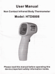
Figure 1Ć1:ăComponents of the AM 503S . . . . . . . . . . . . . . . . . . . . . . . .
Figure 1Ć2:ăTM 502A Voltage Selector . . . . . . . . . . . . . . . . . . . . . . . . . .
Figure 1Ć3:ăChanging the TM 502A Operating Voltage . . . . . . . . . . . .
Figure 1Ć4:ăInstalling the AM 503A Into the Power Module . . . . . . . . .
Figure 2Ć1:ăThe AM 503A Front Panel . . . . . . . . . . . . . . . . . . . . . . . . . . .
Figure 3Ć1:ăConnecting the AM 503A to an Oscilloscope . . . . . . . . . .
Figure 3Ć2:ăConnecting a Current Probe to the AM 503A . . . . . . . . . .
Figure 3Ć3:ăOperating the A6302 Current Probe Slide . . . . . . . . . . . . .
Figure 3Ć4:ăOperating the A6303 Current Probe Slide . . . . . . . . . . . . .
Figure 3Ć5:ăMeasuring Current with the AM 503S . . . . . . . . . . . . . . . . .
Figure 3Ć6:ăEffect of Probe Coupling on LowĆFrequency
Measurements . . . . . . . . . . . . . . . . . . . . . . . . . . . . . . . . . . . . . . . . . . .
Figure 3Ć7:ăApplying the AmpSecond Product Rule . . . . . . . . . . . . .
Figure 3Ć8:ăIncreasing the DC Measurement Range . . . . . . . . . . . . . .
Figure 3Ć9:ăIncreasing Probe Sensitivity . . . . . . . . . . . . . . . . . . . . . . . . .
Figure 3Ć10:ăMeasuring Differential Current and Nulls . . . . . . . . . . . . .
1Ć4
1Ć14
1Ć16
1Ć19
2Ć2
3Ć3
3Ć7
3Ć10
3Ć11
3Ć16
3Ć19
3Ć23
3Ć28
3Ć30
3Ć32
ix
Figure 4Ć1:ăSetup for Measuring Charging Current . . . . . . . . . . . . . . .
Figure 4Ć2:ăCharge Current Waveforms . . . . . . . . . . . . . . . . . . . . . . . . .
Figure 4Ć3:ăMeasuring Inductance with a LowĆImpedance Source . .
Figure 4Ć4:ăLinear Current vs. Time Ramp . . . . . . . . . . . . . . . . . . . . . . .
Figure 4Ć5:ăMeasuring Inductance with a HighĆImpedance Source .
Figure 4Ć6:ăHighĆImpedance Source Current Ramp . . . . . . . . . . . . . . .
Figure 4Ć7:ăMeasuring the Number of Turns in a Coil . . . . . . . . . . . . . .
Figure 4Ć8:ăTurns Measurement Using Reference Coil . . . . . . . . . . . .
Figure AĆ1:ăFrequency Derating Curves . . . . . . . . . . . . . . . . . . . . . . . . .
Figure AĆ2:ăA6302 AmpSecond Product Curve . . . . . . . . . . . . . . . . .
Figure AĆ3:ăA6303 AmpSecond Product Curve . . . . . . . . . . . . . . . . .
Figure AĆ4:ăA6302 Insertion Impedance Curve . . . . . . . . . . . . . . . . . . .
Figure AĆ5:ăA6303 Insertion Impedance Curve . . . . . . . . . . . . . . . . . . .
Figure AĆ6:ăProbe Jaw Dimensions . . . . . . . . . . . . . . . . . . . . . . . . . . . . .
x
4Ć3
4Ć5
4Ć7
4Ć8
4Ć10
4Ć11
4Ć13
4Ć14
AĆ8
AĆ9
AĆ10
AĆ11
AĆ12
AĆ13
%'
& " " !"! %'
& $ " !"! %'
& # " " !"! %'
& $! " !"! '
'
'
'
xi
xii
'%"!+ (%%!' %" ,&' "!&&'& " ! (%%!' %" #% ! (%%!' %" ' (%%!' %"
, "%% &#%', "% & ! "#'"! ! "*% "(
'& ,"( (& "! #%" '" & ('!"(&, &(% !
(%%!' #% "!)%'& ' &!& (%%!' !'" #%"#"%'"! )"' &! '' ,"( ! &(% %', *' ! "&".
&"# "% & % &(%! )
"( ! &' ' #%" '' &' '& ,"(% ##'"! #%"
(&& ") & '" # %"(! ' "!('"% (!% '&' '"! Operation ! '"! Applications #%") !"% '"! '" # ,"(
""& ' "%%' #%" "% ,"(% ##'"!
#%")& ''% !%', '! "'% (%%!' &(% !'
&,&' & (& " (%%!' #%"&& (& *' ' #%" &(% !' #', ! !*' "* ' '" (.
%', %#%&!' &$(% *)& ! &'.%& &!& &!&')', "
' + -& &(% !' #%&"!
1Ć1
! ! !
H
! ! ! ! H
" $
H
%! ! !
! $ ! # " $ ! H
%! ! H
# ! " H
! " H
! ! $ Applications
1Ć2
$! -.) , /,,!). ,*! 3-.!( %)'/ !- .$! "*''*1%)# %.!(-$*1) %) %#/,! 4
H
/,,!). ,*! (+'%"%!,
H
/,,!). ,*! "*, *+.%*)' +,*!- -!! .$! *+.%*)- '%-.
H
*1!, * /'!
H
**'*2
H
*1!, *,
H
/.+/. '!
H
!,(%).%*)
H
-!, )/' ) /%& !"!,!)! ,
) %.%*) .* .$! -3-.!( 3*/ )!! ) *-%''*-*+! .* %-+'3 .$!
(!-/,!(!).- $! *-%''*-*+! ) 1% .$ -$*/' ! ++,*2%4
(.!'3 "*/, .%(!- .$! ) 1% .$ *" 3*/, /,,!). +,*! ) -$*/' ! +4
'! *" %-+'3%)# 0!,.%' -'! ".*, *" ( %0
1Ć3
Output Cable
Power Cord
User Manual
Quick Reference
Termination
AM 503A
TM 502A
Toolbox
A6302 Probe
A6303 Probe (Optional)
Figure 1Ć1:ăComponents of the AM 503S
1Ć4
General Information
' '#!/+( #'(&)"#( (( %!)' #($ #- (&$#,
.
/ $& /'&' %$+& "$)! "%!' (
)&&#( '#' - ( %&$ # $#*&(' ( )&&#( ($ %&$%$&($#!
*$!( (( ' '%!- $# # $'!!$'$% $& $(& '"!& "')&#
*
%&$' *!! $& )' +( ( '-'(" & ( #
( ' %&$' $*& + &# $ %%!($#' $& #$&"($#
$)( ",")" $%&(# !"(' ' %%#, Specifications '(#/
& '-'(" #!)' ( &$ -$) "- $& ')'(()(
( &$ ' ( %($#' !'( # (' '($# $& !(&#(* '-'("
$#)&($#' # %&$' "- !'$ $&& '%/
&(!- $) # '##(!- ,(# ( -#" &# $ ( &$ - )'# ( / /)&&#( &#'$&"& / # $&&
&$" -$)& (&$#, '!' &%&'#((* $& "$& #$&"($# $)( )'#
( / +( ( '-'(" ' ($# Operation
1Ć5
#*% #( & '*' $#%' $#*% &($$ + ''
#$%'& #" '% #% #% , " $'& ($ '# '*#
&" -*' "&'%(!"'& &( & ' #% !-'## ' #")%'%
$#*% #% &($$ & $#*% '# ' #*% #( )%
#$'#"& # ' $#*% #% % ) & ' $#*% #% #$'#"& &'
#('$(' #""'& ' #('$(' # ' '#
+#(% #& #&#$ #% !&(%" )
(& ' #('$(' !$" # ' & ' "$(' !$" # +#(% #& #&#$ !(&' ' "$(' !$" # +#(%
#& #&#$ & '' ' -'%#( '%!"'#" '# ' #& #&#$ "$('
1Ć6
$*$% &$ % ) # $% # !# $ $ $+
$ #$ $ % $ % ) !& % % )%
% % !#
$ &$# & )!$ ( % &$ % &##% $&#%
$*$% "& ## # !# '$ %% # % ! &$%#+
% $%$ $'# ! #%% !#% &$ $%$ % $$%
$%!$ # &##% $&#% #' #% # % &##% # $ % &##% # !# $
!# ' % AM 503S Service Manual !#% $#' $%#&+
% $ # % # % TM 502A Instruction Manual
& ## % ( !% $ # % &##% # *$%
!% % # !% &$%%&% % # # % # 1Ć7
,1 !+ ,."#. 0&# $,)),3'+% -,3#. !,." ,-0',+/ $,. 0&# 1..#+0
., # 5/0#*
-0',+ +'2#./) 1.,-#+ -0',+ +'0#" '+%",* -0',+ 1/0.)' -0',+ ,.0& *#.'! -0',+ 3'06#.)+" ,1 !+ ,."#. 0&# $,)),3'+% ,-0',+) !!#//,.'#/ $,. 0&# 1..#+0
., # 5/0#*
H
#.2'!# +1) #(0.,+'4 -.0 +1* #. 7
7
H
1..#+0 ,,- #(0.,+'4 -.0 +1* #. 77
&# #.2'!# +1) -.,2'"#/ '+$,.*0',+ $,. 0#/0'+% !)' .0'+%
+" 0.,1 )#/&,,0'+% 5,1. /5/0#*
&# !1..#+0 ),,- '/ 1/#" $,. !&#!('+% 0&# -#.$,.*+!# !&.!0#.'/0'!/ ,$ 0&#
#$#. 0, 0&# #.2'!# +1) $,. *,.# '+$,.*0',+ ,10
0&#/# !!#//,.'#/
1Ć8
#! !$( $ ($! $!!# ! ("# %!( ##
($ % # #" ! ($! "("# $!# " "! #"
$ ( # " "" "$# ($! #!' !!"##% !
"""#
"!% # "#( !$#" "! #" "$!( & !#
# $!!# ! ("# &!" $#" !
#!$$# # $ $# ( # ! #" "$!(
" #& #!" ! $"
H
"###" #( #" ! !#" ## $ !"$# # # $# ! #! !!#(
H
"###" #( #" ! !#" ## $ !"$# !" $!( ! "" 1Ć9
& '*" '% & ##% "! $(# !'
H
CAUTION !'& #%&"! !(%+ ,% !"' '+ &&
& "! %& ' %! "% ,% '" #%"#%'+ !(! ' $(#!' '&
H
DANGER !'& #%&"! !(%+ ,% "! %& ' %!
& &+ " ##%& !
'+ && &
!(&
''-!&') )&
& &+ "& ##% "! $(# !'
"'
1Ć10
%"'')
%"(! %'
'% !
% '"
!(
"!% #" !$#" # "$! '$! !" "#' #
!%# # '$! $#
) " !$# " " # !# ! &!
"$! ## & # ' ! # #& # "$' $(
#!" ! #& #! "$' $#! !$ !##% !$
# ' &' # !$ $#! # &! ! " ""(
# ! " !#
) " !$# " !$ #!$ # !$(
$#! # &! ! % #! " $ # &!
! # !!' &! !# ! # $# # #
!$# $# ! $#$# #!" !##% !$ $#! #
&! ! " ""# ! " !#
) "" # !##%
!$ # "" $#% !#" $ " #!" ## ' ! # "$# !! #! "
1Ć11
Use the Proper Power Cord# "
Use the Proper Fuse# ! "
Do Not Operate in Explosive Atmospheres# Do Not Remove Covers or Panels# 1Ć12
General Information
&## % #! "# !"#% % %"#+
%&#$ %( _* _* $%!# % %"#%&#$ #!
_* %! _* $%!# % %"#%&#$ !&%$ % !"#% %$
!( % $$$ %! # % $" !"#% %"#%&# # !#
"") "!(#
!(# !& !"#% #! ! ! !&# '!%$
!"#% '!% $ %# ) % '!% $%!# !% ! %
## " ! % $ &# +
WARNING
To avoid personal injury or equipment damage, do not connect the
power module to the AC line receptacle or turn the power module
on until you have verified that the proper operating voltage is
selected.
1Ć13
Selector Window
Latch
Voltage Selector
TM 502A Power Module
Figure 1Ć2:ăTM 502A Voltage Selector
1Ć14
General Information
$# !& " $" !" %% !# " " $#
&# $" " "% $#! " " "! !"! "
!" " " $#
#! # " " # " $" !" !!&
#"
!!! " $" !" ! !% # '
"" " !" #" " $" ! "
%%
!! " $" !" #! " " "
% # #" " !! " ! " " % " " % # " "
"
1Ć15
Rotate fuse block so that
the correct voltage
appears in the window
Fuse
Fuse Block
Selector Window
Figure 1Ć3:ăChanging the TM 502A Operating Voltage
1Ć16
General Information
" ! ! ! " " ! CAUTION
Make sure the power switch of the power module is off before
installing the AM 503A (and before connecting a current probe to
the AM 503A). If you install or remove a plugĆin instrument while the
power module is on, you might damage the equipment.
! ! ! # ! 1Ć17
! !
Control Summary 1Ć18
Slide instrument into
power module
Release Lever
Figure 1Ć4:ăInstalling the AM 503A Into the Power Module
AM 503S User Manual
1Ć19
$ ! # " " H
"
H
$ H
$ H
! ! "
!
" % "
$ ! $ %
$ # !
1Ć20
)% $ $ #$ "" " )%" #)#$ $"(
"# $ ' %#$" #% "$ #"&#
% )%" #)#$ " " )% $ '# $ #"& $
)%"# $$ )%" "#$ $"( "& $"
"" $ !% $ ##"# $ $"( $
"$ $" $ **
*
1Ć21
1Ć22
! ""# ! % # $ %
! ! ! Operation ApĆ
plications
# % ! % ! Operation
2Ć1
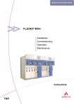
The DC LEVEL knob vertically positions the
signal on the oscilloscope screen. Rotate
the knob to move the signal up or down the
screen.
The OVERLOAD indicator lights when a
measurement exceeds the maximum
continuous current ratings of the AM 503S
system.
The CURRENT/DIVISION display shows
the current AM 503A scale factor in
either mA/division or A/division.
The PROBE OPEN indicator lights when
the attached current probe is unlocked.
The PROBE DEGAUSS AUTOBALANCE
button removes magnetism from the
attached current probe. The probe must
be removed from the test circuit and
locked.
The CURRENT/DIVISION knob changes
the AM 503A scale factor.
The COUPLING switches select AC or DC
probe coupling or a zeroĆcurrent
reference.
The 20 MHz BW LIMIT button alternately
selects or deselects a 20 MHz bandwidth
limit for noise filtering.
The AM 503A output appears at the
OUTPUT connector. Connect this output
to a 50Ă input of your oscilloscope.
The current probes connect to the
AM 503A at the INPUT connector.
Pull the release lever to remove the
AM 503A from the power module.
Figure 2Ć1:ăThe AM 503A Front Panel
2Ć2
Control Summary
" #!"! " !" "" ! " " #"#" " " ! " ! " " !)
' %$ ! " $ " !" " " !! "
!"" ( )# " " !! $ " !" " !
" #! # " " %! " $ " !'
%$ # " !! ! # " #" %! " $ "
%$ % " ! #!"" !!"$"' ! " ! " %$ !
$ " &"' $! # #!""
$ ! " !" ! " #!"" # ! !" % " #"" ! !! " $ ! !" " ( !" " " #" " # ! !" % " #"" ! !! " $ ! " "! # " !""
2Ć3
NOTE
To maintain measurement accuracy, position the signal with the
AM 503A DC LEVEL control. Do not adjust the vertical position
control of your oscilloscope once you have established a zeroĆcurĆ
rent reference.
2Ć4
$ $# $ " "# ) % $$ $ #%"$ ) % "
$ (# $ $% %# !$% $ $ ""$ &" #$%$ %# !" " %# + +%""$ "#+
"" '$ $ " $ &" !" !"##$# $ $
%""$ # $ $ %"$) #%" '$ $ #)#$ &" # $* $ !" ) % # % ')# %## $ !" $" &" $ %"#
WARNING
To avoid personal injury or equipment damage, do not exceed the
specified electrical limits of the AM 503S or any applicable accesĆ
sories.
2Ć5
PROBE OPEN Indicator
%! ! !
! ! ! " ! ! % !
! PROBE DEGAUSS AUTOBALANCE Button
! # ! $& !'
!% ! "
% ! ! " % ! ! %
NOTE
The probe degauss/autobalance routine will not work if the current
probe is unlocked or disconnected from the AM 503A input. To
properly degauss the current probe, remove the probe from the
conductor under test and lock the probe.
2Ć6
Control Summary
! NOTE
The AM 503A front panel digital readout will display an error code
(54) if the AM 503A is not properly terminated into 50Ă at the
oscilloscope input. Refer to Connecting the AM 503A to an OscilĆ
loscope" in Section 3, , for more information.
2Ć7
CURRENT/DIVISION Control
CURRENT/DIVISION %$*(%" )*) * )" *%( )$) * , *. % *
$ //
)'+$ )** $ % * ) %$*(%" ) )&". %$ *
*" (%+* $ * +$ *) $ *%( %** * !$% "%!- ) *% /
() * )" *%( $() * $)*(+#$* )$) * , *. $ %+$*(/
"%!- ) *% $() * )" *%( () * $)*(+#$* )$) * , *.
CURRENT/DIVISION )&". $ *) * )" *%( %$".
#)+(#$* %+*&+* ) )&". %$ * %) ""%)%&
NOTE
To maintain accurate measurements, the vertical gain of the oscilloĆ
scope must remain at 10 mV/div.
COUPLING Buttons
+**%$) *(# $ * %+&" $ *-$ * +(($* &(%
$ * % %+&" * +(($* &(% %( &"+) #)+(/
#$*) &()) * DC +**%$ % %+&" * +(($* &(% %( #)+(/
2Ć8
Control Summary
&% ! ) "$%% & '&&! ! %&% *$!+'$$ & $$ "$%% & '&&! '%& & ! &$! %$ $$
"$%% !'" '&&! &% &! & & %& !
NOTE
To maintain correct operation of the AM 503A coupling buttons,
leave the input coupling of your oscilloscope at DC.
$%% & (& & '&&! &$ &) %&% & '
(& "&) ! & '$$ & "$!
! &! !$ &
* (& % & (& & ' &! ( )!' $ %'$+
!$ !(+$#' ) '$$ &% )!' ( & &! &$ +$#' )
!% & '&&! &% & (& & % ! ( & '&&! % ' & & (& & % !
2Ć9
#%"$ %$!%$ !!"# $ $ $ "
$$ $ $# $ " $ $" $
&"$ !%$ ' %" # # ! %$!%$ ! $
# NOTE
To obtain accurate measurements, the input impedance of your
oscilloscope must be 50 . With 1 M oscilloscopes, use a 50 feedthrough termination (one is supplied with the AM 503S sysĆ
tem). Connect the termination to the oscilloscope input, not the
AM 503A output. Failure to properly terminate the AM 503A will
result in an error code (54) being displayed on the AM 503A front
panel digital readout.
%""$ !" # $$ $ $ $ $ $ " (!
$ " " "$ %$ $$ !" $ $# $ "
# $ Operation
2Ć10
CAUTION
To avoid equipment damage, turn the power module off before
removing or installing any plugĆin unit.
2Ć11
2Ć12
$ $%! $#$ !( %! !"#% % $&$$$ %!#$
*!& $!& ! $# ( $&# &## % (% % $*$%
"" ) Troubleshooting Guide "#!'$ $% ! !! $&#,
% "#!$ %# $!&%! $
!& ( !$!$!" %! $"* % $&# % !&%"&%
! &%+ % & (% "%* ! % %% &## %
"#! % !$!$!" (% $!& ""#!)%* !&# %$ %%
! % &## % "#! !# )" ( &$ "#! % !$!,
$!" (% $!& % $% + &$ "#!
% !$!$!" (% $!& % $% + !$!$!"
&$% $! " ! $"* '#% $ %!# ! '
3Ć1
! ! % % !&%"&% ! %!# %! *!&# !$!$!" &$ ! $ $&"" (% *!&# $*$% ! % ! ! % %! % !&%"&% ! %!# % !%# %! % "&%
! % $# '#% ! *!&# !$!$!" $ &# + "&% " ! % !$!$!" &$% !%#($ *!&
( !& %# $!( "&$ #$"! $ #$ ##%! $ !# !##%
$&# % "%&$
NOTE
If your oscilloscope impedance is 1 M, install a 50 feedthrough
termination at the oscilloscope input connector, not at the AM 503A
output connector (a 50 termination is supplied with the
AM 503S). Failure to properly terminate the AM 503A will result in
an error code (54) being displayed on the AM 503A front panel
digital readout if you attempt to degauss/autobalance the system.
! !"%! "!(# !&$ !( *!& %! #+#!&% % "&+ $%#& %
!&%"&% %! % ## %# ! % "!(# !& ## %! % %#! )
%! !# *!&# %#! ) $$ #"#$ %%' ! +
&# !# !"#%! (% %$ "!(# !&$ $%#&%! $ !# ! &# 3Ć2
AM 503S
Service Manual Test Oscilloscope
AM 503A
A6302 Probe
Output
Input
50Ă Input
Figure 3Ć1:ăConnecting the AM 503A to an Oscilloscope
AM 503S User Manual
3Ć3
" &# $ " " " " !! " %(
#!""! " " ! !! NOTE
Before making any adjustments, allow the equipment, including the
current probe, to warm up for at least 20 minutes.
" " $ " " !! " $
" " !! # ! " " ! "
" " "# " " ! ' (# " " " #" # " !! " # & !! %" " !
!# " !! #" ! " " %" 3Ć4
NOTE
Do not change the vertical amplifier settings of the oscilloscope
while using the AM 503S. All subsequent measurement adjustĆ
ments should be made on the AM 503A amplifier. To maintain
accurate readings, the vertical gain of the oscilloscope channel
must remain at 10 mV/DIV and the coupling must remain at DC.
" "# "!" & # "# $!!# ! ! '$! #
& # !# # $!!# !" % &# # ! " $!!# ! !$' "! '$! # '$
# "$! &(#$ ! (! $' $!!#" #!' $" ! '$ # "$! ! $!!# %$" # &! !(
$" "! $" # ! ! ( ($!!# !"(
3Ć5
!! &# ! "$# # " # #" ' Specifications # #! & ! & &! "# &# ($! " # ! # Applications
CAUTION
Handle the current probes with care. To avoid damaging the probe
core, do not drop the probe or subject it to impact. Also, to avoid
damaging the AM 503A, do not connect or disconnect a current
probe while the probe is clamped around a live conductor or while
the AM 503A is turned on. Excessive voltages and surge currents
can result.
# $!!# ! # # $# #! # # # ! #! &# # "# # $# #! "
$!) # # # ! #! &# # !% # $# #! " "& $! ) $" # ! #!
& #&"# # !! &" # # #!
3Ć6
AM 503A
Push connector in
and twist to lock
Probe
Connector
Probe
Connector
Tab
AM 503A
Slot
(a) Aligning the Tab with the Connector Slot
Groove
Alignment
Dot
(b) Inserting the Connector into the AM 503A
Figure 3Ć2:ăConnecting a Current Probe to the AM 503A
AM 503S User Manual
3Ć7
%""$ " # "$ " $ # # #% $ "!%"
%"$" %#$$ " "!%"# "$ "" $ $ "& % " "$ #$"%$# " $$ )%" $"( #"&
" "#$$&
%""$ "# & # # $$
# ## $ " ' ' )% $ $ " "% $#$ %$" # %#$ $ %"$) #%" %""$ "
$ %## $ " " # % " #$ " $
$ $" ' $
%" + %#$"$# $ # "$ $ " $
" % $ # %$ $ ' # $ " %# $
# "'" %$ $ $$ # # $ %" + %#$"$# $ # "$ $ " $
" "## $ $$ $ %$$ #!%* $ %$ $
" # $ " "# $ #!%* "## $
$ $ %$$
3Ć8
CAUTION
The exposed core pieces are not insulated. To avoid equipment
damage, remove power from an uninsulated wire before clamping
the current probe around it.
3Ć9
Probe Open
Probe Locked
Figure 3Ć3:ăOperating the A6302 Current Probe Slide
3Ć10
Operation
(2)
Lock
the
probe
(1)
Unlock
the probe
(2)
Squeeze
the handle
(1)
Release
squeeze
handle
(a) Opening the Probe
(b) Closing and Locking the Probe
Figure 3Ć4:ăOperating the A6303 Current Probe Slide
AM 503S User Manual
3Ć11
Degaussing the Probes
#% !&(%" (%%"' $%#%! ' $%# (&&('# " %#('"
(&&" ' $%# %!#)& %&( !"'&! %#! ' $%# #%
"'&! " "'%#( !&(%!"' %%#% &( & " +'%"#(& #&' ('# "" %!#)& ("*"' #&'& " ' !$ % %('%,
#!"& " ('#!'& '& ("'#"& " #" (''#"#
"'' ' (&&('# " %#('" $%#%! '& &'$&
ăStep 1:ă%, '' ' (%%"' $%# & #""' '# ' "
%!#) %#! ' #"('#% ("% '&'
ăStep 2:ă# ' $%# & & (%& - " -
ăStep 3:ă%&& ' PROBE DEGAUSS AUTO BALANCE (''#"
NOTE
The AM 503A front panel digital readout will display an error code
(54) if the AM 503A is not properly terminated into 50Ă at the
oscilloscope input. Refer to Connecting the AM 503A to an OscilĆ
loscope," in this section, for more information.
3Ć12
Operation
# !"'" !&(%!"' (%, (&& ,#(% $%# #% # '&
%(!&'"&
H
'% '(%"" ' #" " #*" -!"(' *%!-($ $%#
H
#% #""'" ' $%# '# #"('#% #% "" #"('#%&
H
*")% " #)% # #"'#" #(%&
H
*")% ' $%# & &(' '# &'%#" +'%" !"' #( &#( (&& ' $%# $%# , (%" (& (% '# (&&
' $%# & " (& # !&(%!"' %%#%&
'% ,#( ) #!$ ' ' #& #&#$ (&'!"'& " ' (&&('# " $%#(% ,#(% &,&'! & %, '# !&(% (%%"'
& &'#" &%& #* '# ! " !&(%!"'& #% !#%
!&(%!"' +!$ & & '#" Applications
# !&(% (%%"' $%#%! '& &'$&
3Ć13
ăStep 1:ă#( %% % '#% ! % !$!$!" $ ' %
"&% !&" $ % "&% " $ $% %! ăStep 2:ă&$% % #!& ## ! % !$!$!" $! % )#!*
&## % %# ""#$ % % $# #%& ăStep 3:ă! % "#! "#$$ % REF !&" &%%! % "#$$ % PROBE DEGAUSS AUTOBALANCE &%%! ăStep 4:ă%# % &$$&%! #!&% !"%$ #"!$%!
% #!& ## $$#( ! (!&# !$!$!" &$ %
DC LEVEL ! %#!
ăStep 5:ă" % "#! $ " % "#! #!& % ! &%!#
& # %$% % ! % $
NOTE
For correct measurement polarity, make sure the probe arrow is
pointing in the direction of conventional current flow (conventional
current flow is from positive to negative).
ăStep 6:ă#$$ % DC !&" &%%! $% CURRENT/DIĆ
VISION %! % $# $
3Ć14
Operation
ăStep 7:ă ! DC LEVEL
ăStep 8:ă " ! !
AM 503S User Manual
3Ć15
Power
Supply
-
+
Load
A6302
Current
Probe
Figure 3Ć5:ăMeasuring Current with the AM 503S
3Ć16
Operation
! $&# &## % ! * !!( % $ $ $%#&%! $ !# &## % $&# %$ )"% % !&" %! NOTE
Even when making AC current measurements, leave the oscilloĆ
scope coupling on DC. You need only change the AM 503A couĆ
pling to AC.
*!& %! $&# +"%& &## %$ ! $# &$ +
+&## % # $!## (% "#! + "#!'$ $%"+
!( #%!$ ! !# !# !# !#%! !&% % + ! $&%
*!&# %#! ) $$ #"#$ %%'
3Ć17
Probe Coupling
Considerations
$* # $*%! ) *''#) %'$ )$ ) ,) )' $' $*%!# $*%!# ($,( ) # "(*'"#) $"%$##)(
,! $*%!# &* !. # $#+##)!. '"$+( ) $"%$##)
$*%!# # %'(#) ($" %'$!"( ) '&*#( !$, / $'
-"%! %*!( *''#)( ". -) '$!!$ $' '( "%!)* 0
*'0 ($,( !$,0'&*#. (&*' ,+ $('+ *(# $*%!#
(#! -)( !$,0'&*#. '$!!$ . ## ) $*%!#
)$ ) %*!( !))#( $*) ( ($,# # *' 0
.$* ' )'.# )$ -"# !$,0'&*#. (#! )) ( (*%'"%$( $#
$"%')+!. !' $"%$##) .$* # '($!+ ) (#! . %'0
$'"# )( ()%(
ăStep 1:ă) ) $*%!# )$ AC
ăStep 2:ă
*() ) CURRENT/DIVISION $#)'$! $ ) ($ ))
) (#! ($,( "-"*" )! ,)$*) $# $ ) $(!!$($%
('#
ăStep 3:ă) ) $*%!# )$ DC #)' ) $"%$##) $#
) /'$0*''#) !# . *()# ) DC LEVEL $#)'$! $ ) $, .$* # +, !' $"%$##) (#!( ,)$*) ) (#! '0
)$# )) # $*' ,# !$,0'&*#. (#!( ' $*%!
3Ć18
Operation
(a) ACĆCoupled signal
(b) DCĆCoupled signal
Figure 3Ć6:ăEffect of Probe Coupling on LowĆFrequency Measurements
AM 503S User Manual
3Ć19
%" $! ! # $'"% ! $
& !! '"% !#! ! $!
! # $ "
WARNING
To avoid personal injury or equipment damage, do not exceed the
specified bandwidth limits of your current probe. Measuring freĆ
quencies in excess of the specified limit can cause the probe to
overheat severely.
3Ć20
! # # $ % # Specifications # # $ &
$ # ! " $ $ # # ! $ " " " &
3Ć21
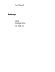
The ampsecond product defines the maximum width of pulsed current that
you can measure when the pulse amplitude is between the maximum
continuous and maximum pulsed current specifications (don't forget to
derate the maximum continuous specification according to the pulse freĆ
quency). If a measurement exceeds the specified ampsecond product,
probe saturation occurs. For convenience, Appendix A, Specifications, rates
the probes in ampmicroseconds and provides an ampsecond curve for
each probe.
To determine if your measurement exceeds the ampsecond product,
perform one of the following steps:
To determine the maximum allowable pulse width, measure the
peak current of the pulse (see Figure 3Ć7). Divide the specified ampĆseĆ
cond (or microsecond) product of your probe by the measured peak
current of the pulse. The quotient is the maximum allowable pulse
width. The pulse width at the 50% point of the measured signal must be
less than this value. For example, if a pulse measured with an A6302
probe had a peak current of 40 A, the maximum allowable pulse width
would be 100 Ams divided by 40 A, or 2.5 ms.
3Ć22
Imax
Maximum
Pulsed
Current
ĂDo Not Exceed
p
Pulse Width
at 50%
50%
Pulse Width
at 50%
50%
Imax
c
Maximum
Continuous
Current
0A
Figure 3Ć7:ăApplying the AmpSecond Product Rule
AM 503S User Manual
3Ć23
$" $ (% ' %# $% *
#%" $ %# '$ $ $ $# # %" * & $
# # " m# "%$ )%" " ) $ %# '$
## " m# !%$$ # $ (% ' %""$ $% $ #%" %# %#$ ## $ $# &% "
( %# #%" '$ " '$ m#
$ (% ' %""$ '% m# & )
m# " NOTE
Always degauss the probe after measuring a current that exceeds
the maximum continuous current, maximum pulsed current, or
ampsecond product rating of the probe. Exceeding these ratings
can magnetize the probe and cause measurement errors.
3Ć24
#( !, "#("'% &'('#"& *% ,#(% !&(%!"' +& ' !+!(! (%%"' %'" # ' #""' $%# & &'#" &(&&& !'#& #% +'"" " (%%"' %"&
WARNING
To avoid personal injury or equipment damage, do not exceed the
specified electrical limits of the AM 503S or any applicable accesĆ
sories.
#( " +'" ' !$ '( !' # ' , (&" ' '%#"+ - -(%%"' %"&#%!% - &" #% (& *' '
(%%"' $%# +'"& ' %" , '#% # #% " " $%#) +'%" (" (%%"' ($ '# #% !#% "#%!'#" #(' ' - #"&( ' ,#(% '%#"+ & & %$%&"'')
(& ' - & #*% "*' !' '" ' $%# &'
' #($ " '# *" (&" ' -
3Ć25
+!' ) & &! %'$ !),"&' !"! & && % %'"$,
"!% ! *&$+ $ %&+ %&& !"! & %' % "!)$ %'""+ !$ +!' ) & &! *& & '$$ & $ ! +!'$ "$!
+!' !%& ' '$$ & )& %! ! '&!$
! %'""+ &! ' '$$ & " %! ! '&!$ && % pure !"! & ! !) (' & "$! ) )& & ! '&!$
' $ &%& % '$ ,
$ & & %! ! '&!$ %! && & ',
'$$ & !)% & !""!%& $&! ! & !) & ! '&!$
' $ &%&
!' $% & (' ! & ' '$$ & + ) '&" &'$ %
! & %! ! '&!$ $!' & "$! % %!) '$ ,
' '$$ & % #' &! & '$$ & !) & ! '&!$ &% &
'$ ! &'$ % )!' $!' & "$! !$ *" & %! ! '&!$ % '$$ & ! !) &$!' & & % )$""
$!' & "$! ( &% & &! ' '$$ & % '&" + !$ ! &$ %'$ & ('% %"+ & (' ! & *&$ ',
'$$ & &! & %"+ %'$ &
3Ć26
WARNING
Under no circumstances should you exceed the maximum continuĆ
ous or pulsed current limits of the probe or the conductors. If the
probe limits are exceeded, remove the conductors from the probe
and perform the probe degauss/autobalance routine.
NOTE
Adding a second conductor to the probe increases the insertion
inductance and reduces the upper bandwidth limit of the probe.
Winding multiple turns further increases the insertion inductance,
further reducing the upper bandwidth limit.
3Ć27
Current
Current
Current
Current
Conductor
Under Test
A6302
Current
Probe
Bucking Current
Supplied by
Second Conductor
(a) Adding a Second Conductor
Conductor
Under Test
A6302
Current
Probe
Extra Turns Added
to Increase
Bucking Current
(b) Adding Multiple Turns
Figure 3Ć8:ăIncreasing the DC Measurement Range
3Ć28
Operation
%! ! #&!% "% &
! %! ! " % % # " ! ! ! ! # ! & ! % ! ! ! "#
" % ! % ! ! ! ! "! $ !&
# ! " # ! ! # " % NOTE
Winding multiple turns around the probe increases insertion inducĆ
tance and reduces the upper bandwidth limit of the probe.
3Ć29
Conductor
Under Test
A6302
Current Probe
Extra Turns for
Increased
Sensitivity
Figure 3Ć9:ăIncreasing Probe Sensitivity
3Ć30
Operation
Measuring
Differential Currents
or Current Nulls
$ $" #& !" #& # $!!# !" !# ! &# '$! "" # "$! !# $!!#
&%! '$ " "$! !# $!!# ! $"# $!!# $"
&# $"# ! $!!# ! ' !! #"
"# "
ăStep 1:ă!# # #& $#!" $! #"# " ## # !#"
" #! # $!!# ! !$ # "
$!)
ăStep 2:ă"$! # $!!# !#' # " ' "$!)
# #" & $#! " !!' # !#! $!!#
ăStep 3:ă $"# ! $!!# $ $"# # $!!# #
$#!" $# # " ' "$!# " (!
AM 503S User Manual
3Ć31
Conductor #2
Conductor #1
Current
Current
A6302
Current Probe
Figure 3Ć10:ăMeasuring Differential Current and Nulls
3Ć32
Operation
# " " " #" " !&! "
# "$! ! " " #& $" !" #" # # ! " !& % ! # " NOTE
The AM 503A front panel digital readout will display error code 54
if the AM 503A is not properly terminated into 50Ă at the oscilloĆ
scope input. Refer to Connecting the AM 503A to an OscilloĆ
scope," in this section, for more information.
" ! ""& "$ !$'!" #" ! "
& !& " " " " ! "# " !" #" " " " !!"! $ " !" #" ! $ & #'
! $ ! " ! " " $ #
3Ć33
!& +! "&+)&$ #,( ++)0 '%* .# +! "*1
($0 ."$$ %'%&+)"$0 $*! +! !)+)* .!& +! "&*+),%&+ "* +,)&
'& ') ++)0 )($%&+ "&*+),+"'&* )) +' +! )-"
&,$
& "+"'& +' &')%$ '()+"'& +! !* +*+ %' .!"! "* ,*
/$,*"-$0 ') *)-""& +! "&*+),%&+ ! +*+ %' "* )"$0 %&+"'&
!) *' +!+ 0', & )'-) *!',$ 0', "&+$$0 "&"+"+ "+ ') %')
"&')%+"'& ',+ +! +*+ %' )) +' +! )-" &,$
CAUTION
Do not run test mode routines. Some routines can destroy RAM
data and impair instrument operation. Test mode should be operĆ
ated by qualified service personnel only.
*+ %' "* &+) 0 ()')%"& +!* *+(*
)** & !'$ +! ,++'&
3Ć34
ăStep 2:ă#!' !"" # PROBE DEGAUSS AUTOBALANCE
$##
ăStep 3:ă" # BW LIMIT $## !$# % "(
' !$# $!
&# # #"# !! #" "# "
ăStep 1:ă!"" # BW LIMIT $## " ## # $## " !
ăStep 2:ă## # DC LEVEL ! !"" # $##" "#!$# "$ !#$! # ! !#
AM 503S User Manual
3Ć35
" !! ! " " &
! ## ""! ! ! & & ! % " ! $ ! & " ! ! "! !!
$! ! ! $ ! % " $! ! !
CAUTION
Avoid using chemical cleaning agents that damage plastic. For
example, avoid using chemicals that contain benzene, toluene,
xylene, acetone, or similar solvents. Recommended cleaning
agents are isopropyl alcohol (Isopropanol) or ethyl alcohol (FotoĆ
col or Ethanol).
! ! ! ! ! # " # ! & ! !
! &" ! !% # !
3Ć36
WARNING
To avoid injury or equipment damage, refer servicing to qualified
service personnel only.
3Ć37
3Ć38
H
H
H
H
4Ć1
$ !!% )$ % # &##% # &% %#+
% # #&% $% &% %' # $*$%$ # %#+!$ %#% #$
(% ##$! %( # $#' % # &##% ('+
# "&* #' #&% $ $ #% # ! $! &##%
%# ( % %% $+!$ !# &$ % %#
'#$ % % % # &##% &##% $&#%
$*$% %% &# * $%% &$* % # * #+
&%&% # &##%
# &# + $ ($ % "&!% $%&! % &##%$
$$ % (% # $*$%$ # $ (% % #"&$
# #* ( &##% # ($ &$ # %$ !!% ($ &$$ % ! # & % ! $%' %%#* # % %#% # &$ % !# $ ## % '% &##%
( % !# ## ( ! %$ (* # % %#% # % (# % %%#*
$ % #&% &% ($ $%#% % %$ (# %&# % $% % % #&%
4Ć2
A6303
+
-
+
Battery
Alternator
-
To
Ground
To Ground
Figure 4Ć1:ăSetup for Measuring Charging Current
AM 503S User Manual
4Ć3
%# &$% % "&!% % % ( $%%$ % (' # #!#*
$% &#
* ($ %
AM 503A
COUPLING DC LEVEL )# *&##% ## $ $% %
$ $ ! # & ## CURRENT/DIVISION BW LIMIT Oscilloscope
&! %$'$ # *&##% # %# #%& $ m$'$ 4Ć4
Applications
! $ ! $ # ! " ! ! # ! # $ ! # "
# # ! $
40A
0A
(a) Normal Waveform
(b) Waveform with One Bad Phase
Figure 4Ć2:ăCharge Current Waveforms
AM 503S User Manual
4Ć5
Inductance
Measurements
" " ! ! " "! $ !
! " ! ! $' " " ! ! ! ! ' " "
$ #"
LowĆImpedance Pulse Sources
" ' $ "! !" " !!'#! " ! %!& $ "!"! "! !
! "!"! ! ! " " "! !'
! ! ! " ! "! "
"! !#& & ! ! "! $ " ' !!& % & ! $
"
L + E dt
di
$ L ! "! E ! #! ! " !
dt ! ! di ! "!
4Ć6
Applications
Current
Flow (i)
Pulse Generator
Inductor
A6302 Current Probe
Figure 4Ć3:ăMeasuring Inductance with a LowĆImpedance Source
AM 503S User Manual
4Ć7
Current Flow (i)
di
Time (t)
dt
4Ć8
! " " $ ! " !!
! "!"! #! ! "! ! "! "! & ! ! !! ! "# " (
$ ! !" $ ! ! #" % "! ! " ( $ $ ! #" ! "(
! " !
! " ! "! ! "! ! "! "(
!
L + ' R
$ L ! "! ! ! " ! "! !
! !! "! #" R ! " ! ! " !
4Ć9
Resistance L
Current
Flow (i)
Pulse Generator
Inductance
A6302 Current Probe
4Ć10
Current Flow (i)
Time (t)
Figure 4Ć6:ăHighĆImpedance Source Current Ramp
AM 503S User Manual
4Ć11
$ ! ! ! ! ! ! # ! & ! ! !
! ! ! ! ! "! ! ! ! ! ! ! !% % ! ! !% # # ! ! ! ! %! # # ! ! ! ! ! &
"!% $ &
! ! ! & ! ! " % ! # # ! ! ! % ! !
N2 + N1 *
Im
I1
# N2 ! ! N1 ! ! Im ! ! I1 ! !&
4Ć12
Measure Input Current Here
Current Flow (i)
Coil
Clamp probe around coil
to measure current from
coil turns
Figure 4Ć7:ăMeasuring the Number of Turns in a Coil
AM 503S User Manual
4Ć13
A6303 Current Probe
Electron Flow in Coil #1
Input Current
Electron Flow in Coil #2
4Ć14
! ! ! ! 4Ć15
4Ć16
' "#" " " #" # $!!# ! ("#
# "("# $" ! $!!# ! &! $ " " #" ! % ( $! # &
#"
H
# "("# " !# # # # !#$! #&
_) _)
H
# "("# " !# %!# &" #" ! "! *
# !# # !#$! #" ! _) # _) $""
#!&" "##
H
# "("# " &!*$
H
# ! $""$# !$# " !! #! #
*$# &!*$ !
H
# " ! !( #!# # )
! # "# $#"
AĆ1
Because of a connector change, these specifications apply only to probes
above certain serial numbers. Refer to the AMĂ503S Service Manual for
more information. Specifications are subject to change without notice.
Specifications are separated into two categories, warranted specifications,
and nominal or typical characteristics.
Warranted characteristics, TableĂAĆ1, are guaranteed performance specificaĆ
tions. See the AM 503S Service Manual for the performance verification
procedures.
Nominal and typical characteristics, TableĂAĆ2, are not guaranteed and are
provided to characterize the configuration, performance or operation of
typical systems.
TableĂAĆ1:ăWarranted AM 503S Characteristics
Characteristic
AM 503A with A6302
AM 503A with A6303
Bandwidth
DC to 50 MHz
DC to 15 MHz
DC Measurement Accuracy
±3%
±3%
Rise Time
v7 ns
v23 ns
AĆ2
Appendix A: Specifications
TableĂAĆ2:ăNominal and Typical AM 503S Characteristics
Characteristic
AM 503A with A6302
AM 503A with A6303
Aberrations
±5%
±5%
Amp@Second Product
100 10Ć6 (100 AĂ·Ăms)
(see amp@second curve in
Figure AĆ2)
10,000 10Ć6 (10,000 AĂ·Ăms)
(see amp@second curve in
Figure AĆ3)
Deflection Factor
ąoscilloscope at 10 mV/div
1 mA/div to 5 A/div
in 1-2-5 increments
10 mA/div to 50 A/div
in 1-2-5 increments
Frequency Derating
maximum continuous current ratĆ
ing decreases above 20 kHz
maximum continuous current ratĆ
ing decreases above 20 kHz
(see frequency derating curve in
Figure AĆ1)
(see frequency derating curve in
Figure AĆ1)
Insertion Impedance
0.1 W at 1 MHz
0.5 W at 50 MHz
(see insertion impedance curve
in Figure AĆ4)
0.02 W at 1 MHz
0.15 W at 15 MHz
(see insertion impedance curve
in Figure AĆ5)
LowĆFrequency Limit
ąAC coupled
v7 Hz
v7 Hz
AM 503S User Manual
AĆ3
TableĂAĆ2:ăNominal and Typical AM 503S Characteristics (Cont.)
Characteristic
AM 503A with A6302
AM 503A with A6303
- #+# %$* $+%+) +(($*
/(* , * ('+$.1
/) +( 0
&! &! - #+# +") +(($*
/$%* *% - * #&)%$
/&(%+*
- #+# %"*
/( , (
%,( %$)+#&* %$
**) #- #+#
**) #- #+#
$%# % )
#
#
AĆ4
Appendix A: Specifications
TableĂAĆ3:ăAM 503S Environmental Characteristics
Name
Description
!% #$%&$
#$%!
_) %" _)
"!*#$%!
_) %" _)
& %(
#$%!
_) %" "!*#$%!
_) %" %%&
#$%!
"!*#$%!
AM 503S User Manual
%
%
' &
' &
AĆ5
TableĂAĆ4:ăAM 503S Physical Characteristics
Name
Description
*( (0
'",#
&& $'
$,#
&& $'
$"#,
&& $'
. ) '$'" +
$"-* 2
&& $'
% '",#
& !,
/$&-& ('-,(* $& , *
1+ $"-* 2
&& $' (*
" +(%$ * .$* *( (0
'",#
&& $'
$,#
&& $'
$"#,
&& $'
. ) '$'" +
AĆ6
$"-* 2
&& $' && $'
% '",#
& !,
/$&-& ('-,(* $& , *
1+ $"-* 2
&& $' (*
" +,*' * .$* Appendix A: Specifications
TableĂAĆ4:ăAM 503S Physical Characteristics
Name
Description
&%! !"#
!$
!
$
!
$
!
$ $
"'
AM 503S User Manual
AĆ7
Maximum Input Current (Amperes P-P)
Frequency
AĆ8
Amperes (Peak)
!
! Allowable Pulse Width (Microseconds)
Figure AĆ2:ăA6302 AmpSecond Product Curve
AM 503S User Manual
AĆ9
# " Amperes (Peak)
$ !
"! !
$ !
Allowable Pulse Width (Microseconds)
AĆ10
Insertion Impedance (Ohms)
Frequency (MHz)
Figure AĆ4:ăA6302 Insertion Impedance Curve
AM 503S User Manual
AĆ11
Insertion Impedance (Ohms)
Frequency (MHz)
Figure AĆ5:ăA6303 Insertion Impedance Curve
AĆ12
Appendix A: Specifications
Maximum Wire Size
3.8 mm (0.15 in)
Maximum Wire Size
21.1 mm (0.83 in)
A6302 Jaw Dimensions
A6303 Jaw Dimensions
Figure AĆ6:ăProbe Jaw Dimensions
AM 503S User Manual
AĆ13
AĆ14
Appendix B: Glossary of Terms
$ ! !
ampsecond product: ! ! $! !
! ! ! ! % ! "!
# $! !! $! ! ! ! ! ! # autoĆbalance: " !# ! % ! $! ! !% ! ! ! bucking current: ! % ! ! #&!% ! ! ! !
# ! ! !%
AM 503S User Manual
BĆ1
! ! ! ! ! !
# # ! ! # !$
" " # ! ! ! ! ! !
# " " # BĆ2
! !" "! ! ! ! ! "! # " ! ! $'"& "! ! ! !! " #! !! ! #
$ ! !" ! # #!
!! !& ! ! ! ! ! !! #! !& ! & ! ! !& "& " ! " ! ! "!
" ! ! $'"& "! ! "#! !" ! ! !
"! $ ! "! " ! ! "!
" % ! "! "! "
! ! & %! ! $ ! !& $ ! " ! ! " & %! !
! !! " $ ! ! !! !
% ! %" # !! ! !"! " ! & ! ! !! "! "! " " "& ! " ! " "'
"! # ! $ " !"! " " ! !"! " BĆ3
BĆ4
Appendix C: Troubleshooting Guide
' $$", '(' $#'' $&# !' (( -#) !- "#)"(& +" !/
')&" )&&"( +( ( ' (' $$", ' %) (&#) '##(/
" &&" #& !#& "/$( ')''#" # )&&"( !')&!"(
$&# !' ' (#" Operation
Problem
Remedy
&#"( $" '$ -' &&#& # 54
H
&# ' "#( (&!"( "(# .W ( #' #'#$ "$)( !/
$" (# .W; '( ( #' #'#$ "$)( #)$ " (# H
#' #'#$ "$)( !$" ' , ( .W (( .W
(&!"(#" '("& ''#&- (# #' #'#$
"$)( # "#( (( (&!"(#" (# #)($)(
H
&!"(#" ' (( (# #)($)( !#* " &/
(( (&!"(#" (# #' #'#$ "$)(
H
((&- ' + ((&- &$ !"( '#) $&#&! %) '&* $&'#"" & (# ( &*
") #& !#& "#&!(#"
&#"( $" '$ - '' LO )&"
$#+&/)$
AM 503S User Manual
CĆ1
Problem
Remedy
"$ # )# """ H
%" $ #$"%$ '$ ' ## $ '" % $
#$"%$ &' #$$ "$ "$ $#
% $ """ $ "##$# "" $ #$"%$ $
!% #"& "# " " "
$ %""$ #%"$
H
" # $ H
" # " ") $ $ $ %$ *
$"
H
% # #$ $ REF #$ $ AC " DC
H
" # $ H
" # " ") $ $ $ %$ *
$"
H
" # &" % " ( # $ $
%## $ "
$ %## $ "
$") $ #%"$
CĆ2
Appendix C: Troubleshooting Guide
%'$ &% $ '$&
H
!'&"'& % !& &$ & &! ! & "'&
" ! !%!%!" &! !$ ! & &$!' &$ &! &! & !%!%!" "'& not &! &
!'&"'&
H
$& "$ ! !%!%!" % !& & (
H
!%!%!" $!' $$ % "$!"$+ '%&
H
! &$! % !& '%& &! & ,$!'$$ & $$ H
%'$ & *% & *' ! & '!'% '$$ &
!$ "%! "$!'& $& % ! & "$! % &! Operation !$ !$ !$&! !'& *' '$$ & $& % "!%% '"$ &! "$! )& $ '$$ &
$& !$ '% -
&$ %!$$
%'$ &% $! ! & $#' %
H
)& & % &'$ ! $+ && )& &
%)&% ! both & & !%!%!" $ %& &!
& ' )& "!%&! %'$ &% $! ! & !) $#' %
H
!'" % %& &! $+ && & !'" %)&% !
both & & !%!%!" $ %& &! & "!%&! CĆ3
!# "! &" &!!$ !
H
! " H
! ' " " " #"
H
#"#" ! " " " " " #"
!! " " (
" # " " " " !! #" not " "
#"#"
H
#"#" ! " " " " " #"
!! " " (
" # " " " " !! #" not " "
#"#"
H
!# " &! " &# "##! # "
! #" "! " (
" ! " Operation !! # " %" # " " #! ( " ! !# " "! & "
! "
CĆ4
!# "! &" &!!$ '
!% #! !!
H
#"#" ! " " " " " #"
!! " " (
" # " " " " !! #" not " "
#"#"
H
!# " &! " ! #" "
! " Operation " #"
! #" !! # " %" # " " #! ( " ! H
%" " ! "# ' "" %" "
!%"! both " " !! !" "
" # %" !"
CĆ5
CĆ6
bucking current, 3Ć26, BĆ1
AC coupling, 2Ć8, 3Ć17, 3Ć18
current limitations
ampsecond product, 3Ć2
maximum continuous, 3Ć21
maximum pulsed, 3Ć21
accessories, 1Ć3
CURRENT/DIV switch, 2Ć8
adjustments
AM 503A, 3Ć13
oscilloscope, 3Ć4
BW LIMIT switch, 2Ć9
applications, 4Ć1
CAUTION
statement in manuals, 1Ć9
statement on equipment, 1Ć10
autoĆbalance, BĆ1
changing the operating voltage, 1Ć13
ampsecond product, 3Ć22, BĆ1
choosing a probe, 3Ć5
continuity measurements, 4Ć15
control summary, 2Ć1
bandwidth limits, 2Ć9, 3Ć20
coupling modes, 3Ć18
batteryĆlow indicator, 3Ć33
COUPLING switch, 2Ć8
conventional current flow, BĆ2
customer support, 1Ć21
DANGER, statement on equipment,
1Ć10
DC coupling, 2Ć8, 3Ć18
DC LEVEL control, 2Ć3, 3Ć15, 3Ć18
degauss function, 2Ć6, 3Ć12, BĆ2
IĆ1
&&#& #' 3Ć33
&&#& 3Ć2, CĆ1
CĆ1
"&'" )" )&&"( 3Ć26
,("" ( )&&"( &" # (
$&#' 3Ć25
"&'" $&# '"'(*(- 3Ć29
")(" !')&!"(' 4Ć6
#""(#& 2Ć10
"'&(#" !$" BĆ3
"'( " ( 1Ć17
&%)"- &(" 3Ć21
&#"( $" #"(&# ' 2Ć1
#" ( $&#' 3Ć8
#+ ((&- "(#" 3Ć33
)'' BĆ2
#''&- # (&!' BĆ1
!,!)! #"(")#)' )&&"( &("
3Ć21
!,!)! $) ' )&&"( &(" 3Ć21
!')&" #"(")(- 4Ć15
!')&" )&&"(
3Ć17
)&&"( ") ' 3Ć31
3Ć13
&"( )&&"( 3Ć31
!')&" ")(" 4Ć6
#$(#" ''#&' 1Ć8
#$(#" $#+& #&' 1Ć8
#$(#"' 1Ć7
#""(#& 2Ć10
"(#& 2Ć5
!"("" 3Ć36
IĆ2
('( "$ 3Ć34
%&(' i
&& #(& $)(%)( 3Ć2
(&$)!'$$( # CĆ1
%$+& $&' 1Ć8
&!' !*& 2Ć11
)(($# 2Ć6 3Ć12
&%!! %&(' i
# ($& 2Ć6
%&$'
#+ ( $#' &( $#' 3Ć20
$)%! # 3Ć18
)'' # "#( . # /
3Ć12
'& %( $# 1Ć5
#&' # ( )&&#( ! " ( 3Ć25
" #(## 3Ć36
", ")" )&&#( ! " (' 3Ć21
$%&( $# 3Ć8
'()&( $# 3Ć21
'!( # 3Ć5
(- -"$!' 1Ć10
'(- #$&"( $# 1Ć9
'()&( $# BĆ3
'% ( $#' AĆ1
($$!$, 1Ć7
*$!( '!($& 1Ć13
'(("#( # "#)! 1Ć9
')'%( ! (- BĆ3
(&" #( $# &' '($& 1Ć6 3Ć2
IĆ3
IĆ4