1
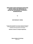
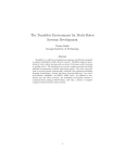
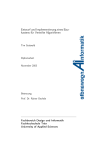
ViSiDiA - User Manual
Cédric Aguerre
<[email protected]>
June 4, 2010
ii
Contents
1 Software installation
1
2 ViSiDiA functionalities
2.1 Graphical User Interface . . . . .
2.1.1 Global view . . . . . . . .
2.1.2 Left menu and top toolbar
2.1.3 Graph panel . . . . . . . .
2.1.4 Secondary toolbar . . . . .
2.2 Message passing simulation . . .
2.2.1 Run the simulation . . . .
2.2.2 View statistics . . . . . . .
2.3 Mobile agent simulation . . . . .
2.4 Mobile sensors . . . . . . . . . . .
2.5 Rewriting rules . . . . . . . . . .
2.6 Specific settings . . . . . . . . . .
2.6.1 Preferences . . . . . . . .
2.6.2 Set properties . . . . . . .
2.6.3 Repat simulations . . . . .
2.6.4 Recording a simulation . .
2.7 Remote network . . . . . . . . . .
.
.
.
.
.
.
.
.
.
.
.
.
.
.
.
.
.
.
.
.
.
.
.
.
.
.
.
.
.
.
.
.
.
.
.
.
.
.
.
.
.
.
.
.
.
.
.
.
.
.
.
.
.
.
.
.
.
.
.
.
.
.
.
.
.
.
.
.
.
.
.
.
.
.
.
.
.
.
.
.
.
.
.
.
.
3 Developing your own agents or algorithms
3.1 General considerations . . . . . . . . . . .
3.2 Developing agents . . . . . . . . . . . . . .
3.2.1 Asynchronous agents . . . . . . . .
3.2.2 Synchronous agents . . . . . . . . .
3.2.3 Sensor agents . . . . . . . . . . . .
3.3 Developing algorithms . . . . . . . . . . .
3.3.1 Asynchronous algorithms . . . . . .
3.3.2 Synchronous algorithms . . . . . .
3.3.3 Sensor algorithms . . . . . . . . . .
3.4 Compiling your agent or algorithm . . . .
3.5 API packages . . . . . . . . . . . . . . . .
3.5.1 Edge states . . . . . . . . . . . . .
3.5.2 Messages . . . . . . . . . . . . . . .
3.5.3 Criteria . . . . . . . . . . . . . . .
iii
.
.
.
.
.
.
.
.
.
.
.
.
.
.
.
.
.
.
.
.
.
.
.
.
.
.
.
.
.
.
.
.
.
.
.
.
.
.
.
.
.
.
.
.
.
.
.
.
.
.
.
.
.
.
.
.
.
.
.
.
.
.
.
.
.
.
.
.
.
.
.
.
.
.
.
.
.
.
.
.
.
.
.
.
.
.
.
.
.
.
.
.
.
.
.
.
.
.
.
.
.
.
.
.
.
.
.
.
.
.
.
.
.
.
.
.
.
.
.
.
.
.
.
.
.
.
.
.
.
.
.
.
.
.
.
.
.
.
.
.
.
.
.
.
.
.
.
.
.
.
.
.
.
.
.
.
.
.
.
.
.
.
.
.
.
.
.
.
.
.
.
.
.
.
.
.
.
.
.
.
.
.
.
.
.
.
.
.
.
.
.
.
.
.
.
.
.
.
.
.
.
.
.
.
.
.
.
.
.
.
.
.
.
.
.
.
.
.
.
.
.
.
.
.
.
.
.
.
.
.
.
.
.
.
.
.
.
.
.
.
.
.
.
.
.
.
.
.
.
.
.
.
.
.
.
.
.
.
.
.
.
.
.
.
.
.
.
.
.
.
.
.
.
.
.
.
.
.
.
.
.
.
.
.
.
.
.
.
.
.
.
.
.
.
.
.
.
.
.
.
.
.
.
.
.
.
.
.
.
.
.
.
.
.
.
.
.
.
.
.
.
.
.
.
.
.
.
.
.
.
.
.
.
.
.
.
.
.
.
.
.
.
.
.
.
.
.
.
.
.
.
.
.
.
.
.
.
.
.
.
.
.
.
.
.
.
.
.
.
.
.
.
.
.
.
.
.
.
.
.
.
.
.
.
.
.
.
.
.
.
.
.
.
.
.
.
.
.
.
.
.
.
.
.
.
.
.
.
.
.
.
.
.
.
.
.
.
.
.
.
.
.
.
.
.
.
.
.
.
.
.
.
.
.
.
.
.
.
.
.
.
.
.
.
.
.
.
.
.
.
.
3
3
3
4
5
5
6
6
8
9
11
13
14
14
15
16
16
17
.
.
.
.
.
.
.
.
.
.
.
.
.
.
19
19
20
20
22
23
23
23
25
26
26
26
26
26
27
iv
CONTENTS
3.6 Developing an algorithm: example of Rendez-Vous
3.6.1 Context . . . . . . . . . . . . . . . . . . .
3.6.2 Algorithm description . . . . . . . . . . .
3.6.3 Implementation using the API ViSiDiA . .
3.6.4 Complete Java code . . . . . . . . . . . . .
Appendices
.
.
.
.
.
.
.
.
.
.
.
.
.
.
.
.
.
.
.
.
.
.
.
.
.
.
.
.
.
.
.
.
.
.
.
.
.
.
.
.
.
.
.
.
.
.
.
.
.
.
.
.
.
.
.
27
27
27
27
28
30
A Install Java
31
A.1 Troubleshooting . . . . . . . . . . . . . . . . . . . . . . . . . . . . . . 31
A.1.1 GNU Java Compiler (GJC) . . . . . . . . . . . . . . . . . . . 31
A.1.2 OpenJDK . . . . . . . . . . . . . . . . . . . . . . . . . . . . . 32
Chapter 1
Software installation
ViSiDiA requires Java 6 or greater to run properly. Please refer to appendix A for
information about Java installation.
Once a recent Java Virtual Machine (JVM) is installed, download visidia.jar and
run it either by double-clicking on it, or from the command line:
$ java -jar visidia.jar
Please visit the website http://visidia.labri.fr for more information.
1
2
CHAPTER 1. SOFTWARE INSTALLATION
Chapter 2
ViSiDiA functionalities
2.1
2.1.1
Graphical User Interface
Global view
When ViSiDiA starts, the main window appears (figure 2.1). The Graphical User
Interface (GUI) consists in four parts:
• at the center, a tabbed panel for displaying different graph views (a single tab
for graph drawing, and a tab for each simulation).
• at the left, a textual menu-like toolbar listing software functionalities relative
to graph edition, simulation and graph view;
• at the top, a toolbar with icons representing the most useful functionalities
associated to the current view;
• at the bottom, a secondary (optional) toolbar used for inputs or information
display.
The contents of toolbars change depending on ViSiDiA running mode. Either you
are editing a graph, or you are visualizing a simulation. So you have access either
to edition or to simulation functionalities. And you always have access to view
functionalities.
3
4
CHAPTER 2. VISIDIA FUNCTIONALITIES
Figure 2.1: ViSiDiA main window
2.1.2
Left menu and top toolbar
Toolbar management
Toolbar position cannot be changed in ViSiDiA window. However, toolbars can be
detached (floated) or attached (docked) to the window. To detach a toolbar from
the window, just drag it outsine the window. To attach a toolbar, use the close
button in the floating toolabr window.
Edition
You can create an empty new graph, load a graph from a file or save a graph to a
file. Graph files are in GML format. When loading a graph, the file selection dialog
contains a checkbox to display or hide the selected graph (default is to display the
graph).
You can undo/redo graph operations: vertex/edge creation, suppression, movement,
merge.
From the edition menu, you can remove or duplicate selected items, complete the
graph or select all elements. If using sensors, you can randomly place sensors on
support graph.
Simulation
From the simulation menu, you can specify the number of simulations (see section 2.6.3). You can either define rewriting rules or select an algorithm/agent from
a file. If using agents, you can randomly place some agent one the graph.
2.1. GRAPHICAL USER INTERFACE
5
From the simulation toolbar, you can start/pause/stop the simulation, and adjust
its speed.
View
In the view menu and toolbar, you can display graph properties (general information,
or information about selection). If a single graph element (vertex or edge) is selected
(either in edition or simulation tabs), you can manage its properties (set, add,
remove), such as label, weight, orientation, and so on.
Zoom functionalities are also available.
The menu contains a checkbox to display or hide the current graph. If the graph is
hidden, the graph panel displays some graph properties in edition mode.
ViSiDiA menu
From the ViSiDiA menu, you can adjust preferences, replay a previously recorded
simulation (see section 2.6.4) and quit the application.
2.1.3
Graph panel
In the edition tab, left click to add a new vertex. Drag with left button pressed to
add an edge.
Right click on vertices and edges to select/unselect them. Drag with right button
pressed to select all items in a rectangular area.
Drag with middle button pressed to move graph elements. If first click in on a selected element, all selected elements move. If first click is on an unselected vertex,
this vertex moves. If first is not on a graph element, the whole graph will move.
Note that moving a vertex implies moving its incident edges.
If you move a vertex on another vertex, the vertices will be merged, and their incident edges are recomputed.
You can remove selected items with either DELETE or BACKSPACE key.
In a simulation tab, you can right click on vertices and edges to select/unselect
them.
2.1.4
Secondary toolbar
The secondary toolbar in edition tab lets you both define the simulation mode and
create a new simulation tab.
There are eight simulation modes, based on a combination of three choices:
• the type of processes, which can be fixed or mobile;
• the type of network in which the processes work, local or remote
• the type of process execution, by passing messages or using mobile agents.
6
CHAPTER 2. VISIDIA FUNCTIONALITIES
When you have created a graph, select the simulation mode and click the "New
simulation" button. If you use fixed processes, a new simulation tab appears.
For the particular case of mobile processes (sensors), you must first define a support
graph for sensors and click the "Set support graph" button to validate, then place
sensors on this support graph, and finally click the "New simulation" button. If you
click the "Set support graph" without defining a graph, ViSiDiA suggests using a
regular grid as a support graph.
2.2
2.2.1
Message passing simulation
Run the simulation
Suppose a graph as illustrated in figure 2.2, and start a new message-passing simulation with fixed processes and local network.
Figure 2.2: A graph created with ViSiDiA
From the "Simulation" menu, select an algorithm using the proposed file dialog.
An algorithm is a compiled Java class. The file dialog contains a short description
2.2. MESSAGE PASSING SIMULATION
7
of each algorithm (figure 2.3). Open the "Spanning_Tree_RDV" algorithm. The
algorithm will be copied to each vertex.
Figure 2.3: Algorithm selection
Right-click on a vertex to select it. Click the "Graph properties" button in view
toolbar or menu. Change the vertex label to "A". Start the simulation (figure 2.4).
On the left side of the window, you can choose the kind of messages to be displayed.
8
CHAPTER 2. VISIDIA FUNCTIONALITIES
Figure 2.4: Message-passing simulation
2.2.2
View statistics
Click the "Statistics" button in the left side of simulation window to visualize the
number of sent messages.
The number of messages is displayed for each simulation (figure 2.5), in case of
multiple (repeated) simulation (see section 2.6.3). Note that if the selected algorithm has no termination detection, statistics will be useless since the number of messages will grow up indefinitely. In the previous example, the "Spanning_Tree_RDV" algorithm has no termination detection. An appropriate algorithm is "Spanning_Tree_ID_With_Termination".
2.3. MOBILE AGENT SIMULATION
9
Figure 2.5: Statistics in message passing simulation
2.3
Mobile agent simulation
Suppose the same graph as illustrated in figure 2.2, and start a new mobile agent
simulation with fixed processes and local network.
Select one or more vertices. From the "Simulation" menu, select an agent using the
proposed file dialog. An agent is a compiled Java class.
Repeat for other agents or vertices in the same graph if needed, then start the
simulation (figure 2.6).
10
CHAPTER 2. VISIDIA FUNCTIONALITIES
Figure 2.6: Mobile agent simulation
Using the buttons on the bottom-left side while the simulation is running, you
can:
• switch a vertex on/off: agents won’t go to switched off vertices;
• delete an agent : a removed agent will come back if you restart the current
simulation;
• view and modify agent properties.
You can display statistics about the mobile agent simulaiton, using the "Statistics" button in the left side of simulation window.
2.4. MOBILE SENSORS
11
Figure 2.7: Statistics in mobile agent simulation
2.4
Mobile sensors
Message-passing and mobile agent simulation is available using mobile processes
(sensors). First define a support graph (either loading an existing graph or using a
regular grid), then place sensors on this support graph (figure 2.8).
12
CHAPTER 2. VISIDIA FUNCTIONALITIES
Figure 2.8: Sensors are placed on a support graph (here a regular grid)
Select an algorithm or agents as described in the previous sections, then start
the simulation. The sensors start moving. If two sensors are close enough, they are
linked by an edge and can exchange messages or agents (figure 2.9). The sensor
communication distance can be set in the ViSiDiA/Preferences menu.
Figure 2.9: Message passing simulation using sensors
2.5. REWRITING RULES
2.5
13
Rewriting rules
Rewriting rules can be defined thanks to the graphical interface, enabling the user
to draw an algorithm only with the mouse. Rules execution can be visualized with
agents or message passing. This depends on the simulation mode you chose in the
graph editor.
A dialog appears when clicking the command Define rewriting rules in the Simulation menu.
From this dialog, you can create a new set of rules, or load a previously saved rewriting rule system.
To create a new set of rules:
• Double click with left mouse button on dashed circle to add a node (and an
edge linking this node to the central node).
• Simple click with right button mouse on a node or an edge to edit its properties.
• Simple click with right button mouse on window background to add or remove
a rule.
Figure 2.10: Example of rewriting rules
On figure 2.10, one of the three rules used to create a spanning tree with termination detection is presented. This rule means :
If u is a node of label "A" with a neighbor of label "A" with a marked edge
between them, and u has no neighbor of label "N" with an unmarked edge
("Context 1"), then u can take the label "F". In fact, there is another
forbidden context hidden under the "Context 2" tab.
14
2.6
2.6.1
CHAPTER 2. VISIDIA FUNCTIONALITIES
Specific settings
Preferences
From Visidia menu, you can adjust preferences relative to graph (figure 2.11), colorpalette (figure 2.12) or sensors (figure 2.13).
Figure 2.11: Adjusting graph preferences
Figure 2.12: Adjusting color palette preferences
2.6. SPECIFIC SETTINGS
15
Figure 2.13: Adjusting sensor preferences
2.6.2
Set properties
Vertices, edges and agents have specific properties, such as labels, weights, etc. You
can adjust these predefined properties and add new ones by selecting one item (vertex, egde or agent) then clicking the Info button in top toolbar. Different types of
properties are available : Boolean, String, Double, Integer. Each new property can
be displayable, which means that it can be visualized on the graph.
Figure 2.14 gives an example of setting an edge properties. Three properties are
specific to edges and cannot be removed (oriented, label, weight). The user has
added two other properties (comment, nbTransfers) which are both displayable, but
only nbTransfers is displayed on the graph.
16
CHAPTER 2. VISIDIA FUNCTIONALITIES
Figure 2.14: Setting properties of an edge
2.6.3
Repat simulations
You can decide to run a same simulation several times in a raw. You must specify
the number of simulations from the corresponding entry in Simulation menu before
clicking the Start button for the first time.
Figure 2.15: Setting the number of simulations
2.6.4
Recording a simulation
You can save a simulation to a file in order to replay it at a later time. You must
click the Record button in left toolbar to choose a record file before clicking the
Start button for the first time.
2.7. REMOTE NETWORK
2.7
Remote network
To be written.
17
18
CHAPTER 2. VISIDIA FUNCTIONALITIES
Chapter 3
Developing your own agents or
algorithms
3.1
General considerations
In ViSiDiA, agents and algorithms can be defined using either a rewriting rule system
or an Application Programming Interface (API). We here only present the creation
of agents and algorithms using the ViSiDiA API.
To create a new agent or algorithm, you must create a new class in a new file.
This must extend one the API classes, depending on the communication mode (synchronous or asynchronous) and the process type (fixed processes or mobile sensors).
Theses API classes are located in the visidia.process.agent and visidia.process.algorithm
packages, respectively. Please refer to the following table to determine which class
to extend.
Fixed processes
Mobile sensors
agents
algorithms
agents
algorithms
Asynchronous
Agent
Algorithm
not implemented
not implemented
Synchronous
SynchronousAgent
SynchronousAlgorithm
not implemented
SensorSyncAlgorithm
In the new class, whatever the class you extend, you have to specifiy at least two
methods:
• public Object clone(); which creates a new instance of your class;
• public void init(); containing the code of your agent or algorithm.
These methods will be called by ViSiDiA when loading and running your agent or
algorithm, respectively.
To implement your algorithm or agent, you have access to several methods defined
in the ViSiDiA API, depending on the API class your algorithm or agent extends.
The following sections describe these methods.
19
20
CHAPTER 3. DEVELOPING YOUR OWN AGENTS OR ALGORITHMS
3.2
Developing agents
Agents are autonomous computation entities which move on the network, using node
ressources when reaching a node. Each agent has its own properties, and can acces
to node whiteboards. Agents can either manage its own movement or use an agent
mover which will automatize the movement.
Movement is defined by an origin vertex (node) and a destination vertex. An agent
operates when it arrived at a vertex. We thus consider that an agent, if on a vertex,
is always on the destination vertex.
3.2.1
Asynchronous agents
General methods
protected Collection agentsOnVertex();
Returns the collection of agents which are on each vertex.
public int getArity();
Returns the destination vertex degree.
protected int getVertexIdentity();
Returns the destination vertex identity.
protected void sleep(int milliseconds);
Pauses the agent during the given number of milliseconds.
protected int getNetSize();
Returns the net size. Provided for convenience, since an agent is not supposed to
know graph global information.
Property methods
public Object getProperty(Object key);
Gets the agent property value associated to the key, or null if the key does not exist.
public Object setProperty(Object key, Object value, int status);
Adds a property to the agent. If the value is null then the property is removed.
Please refer to SimulationConstants.PropertyStatus class to see available statuses.
public Object setProperty(Object key, Object value);
Adds a non-displayable property to the agent. If the value is null then the property
is removed.
public Object removeProperty(Object key);
Removes the property.
3.2. DEVELOPING AGENTS
21
public void resetProperties();
Resets properties to their initial (default) value.
public Set<Object> getPropertyKeys();
Gets all agent property keys.
public boolean containsElement(Object key);
Checks if key matches an agent property.
protected Object getVertexProperty(Object key);
Gets the destination vertex property value associated to the key, or null if the key
does not exist.
protected void setVertexProperty(Object key, Object value, int status);
Adds a property to the destination vertex. Please refer to SimulationConstants.PropertyStatus
class to see available statuses.
protected void setVertexProperty(Object key, Object value);
Adds a non-displayable property to the destination vertex using its previously defined status if any ; else define the property as non-displayable.
protected String getVertexLabel();
Gets the destination vertex label.
protected int getVertexIdentity();
Gets the destination vertex identity.
protected void setVertexLabel(String label);
Sets the destination vertex label.
protected void lockVertexProperties();
Locks the vertex whiteboard where the agent is. If already locked, waits until the
owner unlocks it.
protected void unlockVertexProperties();
Unlocks the vertex whiteboard where the agent is.
protected boolean vertexPropertiesLocked();
Tests if destination vertex properties are locked.
protected boolean lockVertexIfPossible();
Locks the destination vertex; does nothing if it is already locked.
protected Object getEdgeProperty(int door, Object key);
Gets the property value associated to the key of the edge identified by the door
22
CHAPTER 3. DEVELOPING YOUR OWN AGENTS OR ALGORITHMS
number from destination vertex. Returns null if the key does not exist.
protected void setEdgeProperty(int door, Object key, Object value);
Adds a property to the edge identified by the door number from destination vertex.
Visualization methods
protected final void setDoorState(EdgeState st, int door);
Changes the door state and thus the edge color and thickness. The parameter st
can be created using MarkedState or SyncState instances.
Movement methods
protected void move();
Moves the agent using its associated mover.
protected void moveBack();
Moves the agent back to the vertex from where it comes.
protected void moveToDoor(int door);
Moves agent to specific door.
protected int entryDoor();
Returns the door from which the agent comes.
protected void setAgentMover(String name);
Associates a mover to the agent. The parameter is the mover class name.
public Vertex getDestinationVertex();
Returns the agent destination vertex.
3.2.2
Synchronous agents
When creating a new synchronous agent, one method can be redefined in the new
class, in addition to clone() and init() methods:
• protected void planning(SynchronousAgent agent); defines what two agents
(current agent and the one given in parameter) do when they meet.
public int getPulse();
Gets the current pulse. This value is associated to the simulator, and thus shared
by all running agents.
3.3. DEVELOPING ALGORITHMS
23
public void nextPulse();
The node asks for a new pulse to begin. The method waits until all agents have
called this method.
3.2.3
Sensor agents
To be written.
3.3
Developing algorithms
In ViSiDiA, the same algorithm is copied to each process (each node). Each cloned
algorihm is thus related to a node. When one of the following methods is called, it
refers to the node to which the current algorithm copy belongs. Each node has a
whiteboard, an editable set of its properties.
When creating a new algorithm, two methods can be redefined in the new class,
in addition to clone() and init() methods:
• public String getDescription(); contains the algorithm description which
appears to the user, for example when loading the file;
• public Collection<MessageType> getMessageTypeList(); gives the list
of messages the user can display or hide while the simulation is running.
3.3.1
Asynchronous algorithms
General methods
protected int getArity();
Returns the node degree.
protected int getId();
Returns the node id.
protected int getNetSize();
Returns the net size. Provided for convenience, since an algorithm is not supposed
to know graph global information.
protected Enumeration<Integer> getOrientedDoors();
Gets the oriented doors of the current node. Both incoming and outgoing doors are
considered.
protected boolean isIncomingDoor(int door);
Returns true if the door corresponds to an edge pointing to the current node. Also
returns true if the edge is not oriented.
24
CHAPTER 3. DEVELOPING YOUR OWN AGENTS OR ALGORITHMS
protected boolean isOutgoingDoor(int door);
Returns true if the door corresponds to an edge leaving the current node. Also
returns true if the edge is not oriented.
Property methods
protected void putProperty(String key, Object value, int status);
Adds a property to the node. Please refer to SimulationConstants.PropertyStatus
class to see available statuses.
protected void putProperty(String key, Object value);
Adds a property to the node using its previously defined status if any ; else define
the property as non-displayable.
protected Object getProperty(String key);
Gets the node property value associated to the key, or null if the key does not exist.
protected Object getEdgeProperty(int door, String key);
Gets the property value associated to the key of the edge identified by the door
number from current vertex, or null if the key does not exist.
protected void setEdgeProperty(int door, String key, Object value);
Adds a property to the edge identified by the door number from current vertex.
Visualization methods
protected final void setDoorState(EdgeState st, int door);
Changes the door state and thus the edge color and thickness. The parameter st
can be created using MarkedState or SyncState instances.
Communication methods
For communication purposes, each node identifies the path to its neighbors using
"doors". A door is a unique integer identifier between 0 (included) and the number
of neighbors minus one.
protected boolean sendTo(int door, Message msg);
Sends the message on outgoing door.
protected void sendAll(Message msg);
Sends the message to all neighbors.
protected Message receiveFrom(int door);
Gets the first message arriving on the specific door. The algorithm is blocked until
3.3. DEVELOPING ALGORITHMS
25
reception.
protected Message receiveFrom(int door, MessageCriterion mc);
Gets the first message arriving on the specific door that matches the criterion mc.
The algorithm is blocked until reception.
protected Message receive(Door door);
Gets the first message arriving on the node through the specific door. The algorithm
is blocked until reception.
3.3.2
Synchronous algorithms
Synchronization methods
public int getPulse();
Gets the current pulse. This value is associated to the simulator, and thus shared
by all running algorithms.
public int nextPulse();
The node asks for a new pulse to begin. The method waits until all algorithms have
called this method.
Communication methods
protected boolean sendTo(int door, Message msg);
Stores the current pulse into the message, and sends the message on outgoing door.
protected final Message getNextMessage(DoorPulseCriterion dpc);
Gets the first message arriving that matches the criterion dpc. If no message has
arrived, the algorithm does not block until reception but returns null.
protected final Message receive(Door door);
Returns the first message arrived in the previous pulse and writes the door number
in the Door object.
protected final boolean existMessage(DoorPulseCriterion dpc);
Returns true if there exists a message that matches the dpc criterion in the message
queue of the node.
protected final boolean anyMsg();
Returns true if the node has received any message which has been sent in the previous pulse.
26
CHAPTER 3. DEVELOPING YOUR OWN AGENTS OR ALGORITHMS
3.3.3
Sensor algorithms
public void move(int sensorId);
Moves a sensor to a support vertex chosen by its associated mover.
public void moveAfterEnd(int sensorId);
Moves a sensor after algorithm end.
3.4
Compiling your agent or algorithm
Before you can compile your new java file, get the visidia_api.jar file, and suppose
you put it in a directory referred to as $VISIDIA_API_PATH.
Then compile your file with the following command:
$ javac -classpath $VISIDIA_API_PATH/visidia_api.jar YourClass.java
You then run ViSiDiA as usual. When selecting an agent or an algorithm, click
"Add new" in the selection dialog, and browse to YourClass.class. Select it, and
you can execute it!
Note that you don’t need to add this class again (even if you close and restart
ViSiDiA) except if you remove the class from the selection dialog.
3.5
3.5.1
API packages
Edge states
A process (algorithm or agent) may change the state of a graph edge. ViSiDiA offers
marked (class MarkedState) and synchronized (class SynchronizedState) states.
The user can define its own states by extending the class EdgeState.
One can find these classes in the visidia.simulation.process.edgestate package.
3.5.2
Messages
Algorithms send messages on the graph. ViSiDiA offers the possibility of sending
messages representing integer values (class IntegerMessage), boolean values (class
BooleanMessage), string values (class StringMessage), vectors of information of
different types (class VectorMessage), and the information about a neighbor (class
NeighborMessage). The user can define its own messages by extending the class
Message.
One can find these classes in the visidia.simulation.process.messages package.
3.6. DEVELOPING AN ALGORITHM: EXAMPLE OF RENDEZ-VOUS
3.5.3
27
Criteria
An algorithm may decide to receive the messages complying with a number of criteria, for example by type (classes MessageCriterion, IntegerMessageCriterion,
MessagePacketCriterion) or by provenance (classes DoorCriterion, DoorPulseCriterion).
It is possible to have a criterion which is the combination of several others (class
CompoundCriterion). The user can define its own criteria by extending the class
Criterion.
One can find these classes in the visidia.simulation.process.criterion package.
3.6
3.6.1
Developing an algorithm: example of RendezVous
Context
We have defined a non-oriented graph. The algorithm (the rendez-vous) is duplicated
on each graph vertex. It means that each node executes the same algorithm, and
that all executions are independent.
3.6.2
Algorithm description
Consider the algorithm on a given vertex V.
The algorithm randomly selects a neighbor N of V, then sends 1 to N and 0 to all
other neighbors of V.
If at the same time V receives 1 from the algorithm on N, then we say that the
rendez-vous is set between V and N.
When a rendez-vous is scheduled between two nodes, the edge connecting them is
marked and algorithms on V and N send each other a "Hello" message. When both
have received this message, the edge is unmarked.
3.6.3
Implementation using the API ViSiDiA
Randomly select a neighbor
We get the arity of V (its number of neighbors), and randomly choose a door (an
integer value between 0 and the number of neighbors minus one).
int nbNeighbors = getArity();
java.util.Random r = new java.util.Random();
int neighborDoor = r.nextInt() % nbNeighbors;
Send synchronization messages (0 and 1)
We use the sendTo method with two parameters: the chosen door and an IntegerMessage.
for (int i = 0; i < nbNeighbors; ++i)
sendTo(i, new IntegerMessage(i == neighborDoor ? 1 : 0));
28
CHAPTER 3. DEVELOPING YOUR OWN AGENTS OR ALGORITHMS
Receive a message
The method receiveFrom(door) waits for a message coming from door.
boolean rendezVousAccepted = false;
for (int i = 0; i < nbNeighbors; ++i) {
IntegerMessage msg = (IntegerMessage) receiveFrom(i);
if ((i == neighborDoor) && (msg.value() == 1))
rendezVousAccepted = true;
}
Mark an edge and send a "Hello" message
The method setDoorState changes the state of a given door; here we use a MarkedState
(marked or unmarked depending on the boolean parameter).
if (rendezVousAccepted == true) {
setDoorState(new MarkedState(true), neighborDoor);
sendTo(neighborDoor, new StringMessage("Hello"));
receiveFrom(neighborDoor);
setDoorState(new MarkedState(false), neighborDoor);
}
Remarks
• Since the receiveFrom method waits until a message arrives, it is guaranteed
that the edge is unmarked only when "Hello" messages have been exchanged.
• The previous code must be placed inside an infinite loop to execute itself untill
the user stops it using the GUI buttons.
3.6.4
import
import
import
import
Complete Java code
visidia.simulation.process.algorithm.Algorithm;
visidia.simulation.process.edgestate.MarkedState;
visidia.simulation.process.messages.IntegerMessage;
visidia.simulation.process.messages.StringMessage;
public class MyRendezVous extends Algorithm {
@Override
public Object clone() {
return new MyRendezVous();
}
@Override
public void init() {
java.util.Random r = new java.util.Random();
int nbNeighbors = getArity();
3.6. DEVELOPING AN ALGORITHM: EXAMPLE OF RENDEZ-VOUS
29
while (true) {
// Randomly select a neighbor
int neighborDoor = r.nextInt() % nbNeighbors;
// Send synchronization messages (0 and 1)
for (int i = 0; i < nbNeighbors; ++i)
sendTo(i, new IntegerMessage(i == neighborDoor ? 1 : 0));
// Receive a message
boolean rendezVousAccepted = false;
for (int i = 0; i < nbNeighbors; ++i) {
IntegerMessage msg = (IntegerMessage) receiveFrom(i);
if ((i == neighborDoor) && (msg.value() == 1))
rendezVousAccepted = true;
}
// Mark an edge and send a "Hello" message
if (rendezVousAccepted == true) {
setDoorState(new MarkedState(true), neighborDoor);
sendTo(neighborDoor, new StringMessage("Hello"));
receiveFrom(neighborDoor);
setDoorState(new MarkedState(false), neighborDoor);
}
}
}
}
30
CHAPTER 3. DEVELOPING YOUR OWN AGENTS OR ALGORITHMS
Appendix A
Install Java
You must have either a Java Runtime Environment (JRE) or a Java Development
Kit (JDK) in version 6 installed on your computer. A JRE is enough to run ViSiDiA. If you plan to develop algorithms, please install a JDK.
If you do not have a JRE/JDK, of if its version is prior to version 6, please download
and install JRE/JDK 6.
You can get the last official Sun JRE/JDK :
http://java.sun.com/javase/downloads/index.jsp
or get an open source JDK, such as OpenJDK :
http://openjdk.java.net/
Under linux Ubuntu, you can for example get openjdk-6:
$ sudo apt-get install openjdk-6-jdk
Important note: Depending on your operating system, you may encounter problems with some open source JRE/JDK. Please refer to section A.1.
You may need to adjust your JAVA_HOME environment variable, for example:
$ export JAVA\_HOME=/usr/lib/jvm/java-6-openjdk/
Under Windows, you may have to set the PATH environment variable to the JDK
binaries.
A.1
A.1.1
Troubleshooting
GNU Java Compiler (GJC)
Please check that you DO NOT USE a JDK from the GJC. To check, run on
command line:
$ java -version
$ javac -version.
If your system is configured to use GJC, please download and install another JDK,
and use it as default.
31
32
APPENDIX A. INSTALL JAVA
A.1.2
OpenJDK
You may encounter problems using OpenJDK with Fedora distribution: Java does
not execute, or ViSiDiA graphical interface is altered (buttons are misalignmed for
example). In this case, please install and use the official Sun JRE/JDK.
Here is the recipe to install Sun JDK on Fedora (example is given for JDK 6 Update 16):
* Get the last JDK version on http://java.sun.com/javase/downloads/index.jsp
Get the file with .bin extension, not the one with .rpm.bin extension.
* Intall the JDK (you need root privileges)
$
$
$
$
$
chmod a+x jdk-6u16-linux-i586.bin
mv jdk-6u16-linux-i586.bin /usr/lib/jvm/
cd /usr/lib/jvm
./jdk-6u16-linux-i586.bin
alternatives --install /usr/bin/java java \
/usr/lib/jvm/jdk1.6.0_16/bin/java 3
$ /usr/sbin/alternatives --config java
(select 3 and enter)
* install the Java plugin for firefox (you need root privileges)
$ usr/sbin/alternatives --install /usr/lib/mozilla/plugins/libjavaplugin.so \
libjavaplugin.so \
/usr/lib/jvm/jdk1.6.0_16/jre/plugin/i386/ns7/libjavaplugin_oji.so 2
$ /usr/sbin/alternatives --config libjavaplugin.so
(select 2 and enter)