1
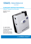
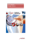
DROPPED FOOT STIMULATOR
USER MANUAL
Caution:
Federal Law restricts this device to sale by or on
the order of a practitioner licensed by the law of
the state in which he/she practices to use or order
the use of the device.
CONTACT INFORMATION
Please contact your Clinician or Therapist if you are experiencing
any difficulties.
Clinicians Name: __________________________________
Phone: ___________________________________________
Therapists Name: __________________________________
Phone: ___________________________________________
NDI Medical
One Chagrin Highlands
2000 Auburn Drive, Suite 320
Cleveland, OH 44122
216.378.9106
www.odfs.com
001-MAN-000-1
001-MAN-000-1
TABLE OF CONTENTS
1.0
2.0
3.0
4.0
5.0
6.0
7.0
8.0
8.1
8.2
8.2.1
8.2.2
8.2.3
8.2.4
8.2.5
8.2.6
8.2.7
8.2.8
8.2.9
8.3
9.0
9.1
9.2
9.3
9.4
9.5
9.6
9.7
10.0
11.0
12.0
i
Introduction ............................................................. 1
Indications for Use .................................................. 1
Contraindications ................................................... 1
Warnings ................................................................. 2
Precautions............................................................. 3
Adverse Reactions ................................................. 4
Contents of Standard Package .............................. 5
Description of System Components ...................... 6
Device Description ................................................. 6
Patient System Components .................................. 7
Stimulator ................................................................ 7
Electrode Leads ..................................................... 8
Electrodes .............................................................. 8
Elastic Tubing ......................................................... 9
Battery .................................................................... 9
Cork Inner sole ........................................................ 9
Foot Switch Lead ................................................... 9
Foot Switch ........................................................... 10
Carrying Case ...................................................... 10
Additional Accessories ........................................ 10
Operating the ODFS System ............................... 10
Preparing the Skin ................................................ 10
Electrode Placement ............................................ 11
Stimulator Set Up .................................................. 13
Connecting the Foot Switch ................................. 14
Using Stimulation .................................................. 15
Removing the ODFS System ............................... 16
Cleaning and Maintenance ................................... 17
Troubleshooting ...............................................18-19
Travel or International Use .................................... 19
Glossary ................................................................ 20
ODFS Dropped Foot Stimulator User Manual
13.0
14.0
15.0
16.0
Specifications ....................................................... 21
ODFS Components and Accessories .................. 22
Warranty ................................................................ 24
ODFS Dropped Foot Stimulator
- Electrode Position Worksheet ........................... 25
LIST OF FIGURES
Figure 1.
Figure 2.
Figure 3.
Figure 4.
Figure 5.
Figure 6.
Stimulator Front Panel ..................................... 7
Electrode Leads and Electrodes ..................... 8
Foot Switch Lead and Foot Switch.................. 9
Electrode Placement ..................................... 12
Adjustment for Turning the Foot to the
Outside…………………………………………. 14
Foot Switch .................................................... 15
LIST OF TABLES
Table 1.
Table 2.
Basic Troubleshooting Tips ......................18-19
System Components ..................................... 22
ODFS Dropped Foot Stimulator User Manual
ii
1.0
INTRODUCTION
This manual is intended to provide information for the safe use
of the ODFS Dropped Foot Stimulator for you and your caregiver.
Your therapist will train you to use the information in this manual.
Call your therapist if you need help in understanding how to use
your ODFS.
2.0
INDICATIONS FOR USE
The ODFS is a device that uses low levels of electrical stimulation to help those having a dropped foot lift their foot and improve their walking.
Additional benefits may include
y muscle re-education (retraining your muscles to act as they
did before your injury)
y prevention/retardation of disuse atrophy (decrease bulk of
muscle tissue when your muscles are not used)
y maintained or increased joint range of motion
y increased local blood flow
The ODFS is a medical device and should only be used under
medical supervision for adjunctive therapy for the treatment of
dropped foot following an upper motor neuron injury.
3.0
CONTRAINDICATIONS
The ODFS should not be used on patients who have a cardiac
pacemaker, implanted defibrillator, or other implanted metallic
or electronic device. Such use could cause electrical shock,
burns, electrical interference, or death.
1
ODFS Dropped Foot Stimulator User Manual
4.0
WARNINGS
Neck Stimulation - Stimulation should not be applied over the
patient's neck, because severe spasm of the muscles may occur and the contractions may be strong enough to close the airway or cause difficulty in breathing. Stimulation over the neck
could also have adverse effects on the patient's heart rhythm or
blood pressure.
Chest Stimulation - Stimulation should not be applied across
the patient's chest because the introduction of electrical current
into the chest may cause rhythm disturbances to the patient's
heart, which could be lethal.
Open or Infected Wounds - Stimulation should not be applied
over open wounds or over swollen, infected, or inflamed areas
or skin eruptions, e.g. phlebitis, thrombophlebitis, varicose
veins.
Cancer - Stimulation should not be applied over, or in proximity
to, cancerous lesions.
Electronic Monitoring Equipment - Stimulation should not be
applied in the presence of electronic monitoring equipment, such
as cardiac monitors and ECG alarms. Monitoring equipment
may not operate properly when the electrical stimulation device
is in use.
Bathing/Showering - Stimulation should not be applied when
the patient is in the bath or shower.
Sleeping- Stimulation should not be applied when the patient
is sleeping.
Machinery Operation- Stimulation should not be applied when
the patient is driving, operating machinery, or during any activity in which electrical stimulation can put the patient at risk of
injury.
ODFS Dropped Foot Stimulator User Manual
2
Consult with the patient's physician before using this device,
because the device may cause lethal rhythm disturbances to
the heart in susceptible individuals.
Stimulation should only be applied to normal, intact, clean skin.
5.0
PRECAUTIONS
Long-term Effects - The long-term effects of electrical stimulation are unknown.
Transcerebral Stimulation - The effects of stimulation of the
brain are unknown. Therefore, stimulation should not be applied across the patient's head and electrodes should not be
placed on opposite sides of the head.
Gynecology - Caution should be used over the menstruating
or pregnant uterus.
Sensory Loss - Caution should be used over areas of skin
that lack normal sensation.
Keep Out of Reach of Children - Keep this device out of the
reach of children.
Electrodes/Leads - Use this device only with the leads, electrodes, and accessories recommended by the manufacturer.
Spasticity - If stimulation causes increased spasticity (involuntary, exaggerated muscle stiffness and spasm), discontinue use
and consult your physical therapist.
Pregnancy - The safety of using electrical stimulation during
pregnancy has not been established.
Supervision of a Licensed Practitioner - Use this device only
under the continued supervision of a licensed practitioner.
Skin Irritation - Some patients may experience skin irritation or
hypersensitivity due to electrical stimulation or electrical conductive medium (gel). The irritation can usually be reduced by using
an alternate electrode placement. A slight reddening of the skin
under the electrode is normal. If stimulation causes long-term marking of the skin, discontinue use and consult your physical therapist.
Latex Allergies- Caution: The Tubigrip elastic stocking contains natural Rubber Latex which may cause allergic reactions.
This item is provided as an accessory to the ODFS device. If
you are sensitive to products that contain latex, your clinician
will discuss possible alternatives (to using this elastic stocking)
with you.
Cardiac - Patients with suspected or diagnosed heart disease
should follow precautions recommended by their physicians.
6.0
Epilepsy - Patients with suspected or diagnosed epilepsy
should follow precautions recommended by their physicians.
Hemorrhage - Caution should be used if the patient has a tendency to bleed internally, such as following an injury or fracture.
Recent Surgery - Caution should be used following recent surgical procedures when stimulation may disrupt the healing process.
3
ODFS Dropped Foot Stimulator User Manual
ADVERSE REACTIONS
Skin Irritation - Skin irritation and burns beneath the electrodes
have been reported with the use of electrical stimulators applied to the skin.
Headache/Painful Sensations - Headache and other painful
sensations have been reported during or following the application
of electrical stimulation near the eyes and to the head and face.
ODFS Dropped Foot Stimulator User Manual
4
Report any undesirable outcomes, malfunctioning of the device,
mistakes in using the device, or injury from the use of this device to your clinician. Your clinician is responsible for reporting
all of these events to the designated US distributor of the ODFS,
NDI Medical, in writing:
y
y
y
7.0
8.0
DESCRIPTION OF SYSTEM COMPONENTS
8.1
DEVICE DESCRIPTION
Stimulator
via email [email protected]
or fax 216-378-9116
or mail to NDI Medical, 2000 Auburn Drive Suite 320, Cleveland, OH 44122
Electrodes
CONTENTS OF STANDARD PACKAGE
The ODFS System contains the following components:
y
y
y
y
y
y
y
y
y
y
y
5
ODFSIII V6.2 Stimulator
(1) set of electrode leads (1m)
(2) packages of PALS neurostimulation 5cm x 5cm square
Platinum Blue electrodes
(1) elastic stocking (Tubigrip size F) Caution: This product contains natural Rubber Latex which may cause allergic reactions.
(1) alkaline battery (9V)
(1) pair of cork insoles (Size 10.5 )
(1) foot switch lead (1.2m)
(2) foot switches
(1) carrying case
(1) User Manual
(1) User Quick Reference Guide
ODFS Dropped Foot Stimulator User Manual
Foot Switch
Stimulating a nerve in the
side of your leg will activate
the muscles that lift the foot.
The stimulation is timed by
using a "foot switch" that is
worn inside your shoe under
the heel of your foot.
The ODFS System is made
up of several parts connected
together and worn on your
body. The stimulator allows
you to turn the system on and
off and to make some adjustments as instructed by your
therapist.
The stimulator is an electronic device about the size
of a pack of playing cards. It
may be worn on a belt clip or
in your pocket. The electrode leads are cables worn under your
clothing that connect the stimulator to self sticking skin surface
electrodes on the side of your leg. A small foot switch is placed
in your shoe under the heel. The foot switch is connected to the
stimulator by a separate lead. The foot switch turns the stimulation on and off in time with your walking pattern. The cork
insole keeps the foot switch in the correct position in your shoe.
The elastic tubing helps keep the electrodes and cables in the
proper position.
ODFS Dropped Foot Stimulator User Manual
6
8.2
PATIENT SYSTEM COMPONENTS
8.2.2
8.2.1
Stimulator
The Electrode Lead is a cable that connects your stimulator to
your electrodes (see Figure 2).
The stimulator generates the electrical stimulation. It is lightweight, wearable and battery operated. The stimulator is programmed by your therapist specifically for you. Figure 1 displays the front panel of the stimulator.
Electrode
Jack
Pause
Button
Output
Test Foot Switch
Button
Jack
Electrode Leads
Pause Button
Electrodes
Leads
Electrodes
Connections
Stimulator
!
Figure 2. Electrode Leads and Electrodes
Belt Clip
On/Off/ Level
Figure 1. Stimulator Front Panel
Electrode Jack - jack for the electrode lead
Pause Button - temporarily turns stimulator off
Test Button - checks the electrode position and output level
Foot Switch Jack - jack for foot switch
On/Off Level - turns stimulator on/off and increases stimulus
Belt Clip - clip for attaching to belt/clothing
Battery Indicator - flickers yellow showing output, flickers red
showing low battery
7
ODFS Dropped Foot Stimulator User Manual
8.2.3
Electrodes
Electrodes are reusable and self sticking to the skin (see Figure 2). Electrodes conduct the stimulation through the skin into
the nerve and muscle of your lower leg. The usual electrode
size is 5 cm x 5 cm. At times, your therapist may choose to use
a different size based on your size and comfort. Your electrodes
should be reused for a period of time. It is important to replace
your electrodes when they become worn or loose their stick. A
pair of electrodes usually last about one month of daily use.
ODFS Dropped Foot Stimulator User Manual
8
8.2.4
8.2.8
Elastic Tubing
Foot Switch
Elastic tubing (Tubigrip - Size F) aids in securing your electrodes and leads around your leg. Caution: This product contains natural Rubber Latex which may cause allergic reactions.
A small foot switch is placed in the shoe under your heel (see
Figure 3). The foot switch turns the stimulation on and off in
time with your walking.
8.2.5
8.2.9
Battery
Your stimulator is powered by one standard 9V alkaline battery.
8.2.6
Cork Insole
The foot switch is adhered to the underside of a cork insole to
maintain the correct position of your foot switch within your shoe.
The insole transfers easily between your shoes.
8.2.7
Foot Switch Lead
The foot switch lead is a cable that connects your stimulator to
your foot switch (see Figure 3).
Carrying Case
A carrying case is included to help protect and keep the system
clean. Store your stimulator and lead wires in the case when
they are not in use.
8.3
ADDITIONAL ACCESSORIES
Additional accessories, such as alternate lead lengths are available
from your therapist. Your therapist will determine if you require any of
these accessories.
9.0
OPERATING THE ODFS SYSTEM
9.1
PREPARING THE SKIN
Properly caring for your skin where the electrodes will be placed
is important and may have the following benefits:
Stimulator
Foot Switch
Lead
y
y
y
y
Foot Switch
Prepare your skin under the electrodes as follows:
1.
Connections
2.
Figure 3. Foot Switch Lead and Foot Switch
9
ODFS Dropped Foot Stimulator User Manual
Allows for more stimulation to reach the desired area
Prolongs the life of the electrodes
Reduces the risk of skin irritation
Could improve your comfort
Wash your electrode sites with mild soap and water. Rinse
and dry thoroughly.
Trim excess body hair from the electrode sites with scissors. DO NOT shave the site. Shaving may cause increased
sensitivity.
ODFS Dropped Foot Stimulator User Manual
10
NOTES:
y Do not place your electrode on cut, broken, or irritated skin.
y Do not use skin creams near the electrode sites.
y If skin irritation develops, remove your electrodes and discontinue using the stimulator. Consult your therapist or clinician.
9.2
3.
4.
5.
6.
7.
8.
y
ELECTRODE PLACEMENT
Position yourself comfortably in a straight backed chair. When
finding the electrode position and testing the device it is best to
have your leg straight.
1.
2.
NOTE: Your therapist may give you different electrode placement instructions to get the best result for you. Follow your
therapist's home going instructions including the electrode position worksheet on page 25 of this manual.
Be sure the stimulator is turned off.
Connect the electrodes to the leads by inserting the pin on
into the connector on the end of the electrode. Push the pin
all the way in so no bare metal is seen. Repeat this step
for your second electrode.
Remove any oil or lotion from your skin before applying electrodes. See section on Preparing the Skin.
Check your skin for cuts, abrasions or reddened areas. Do
not apply electrodes over these areas. Contact your therapist
for instructions.
Peel the electrode away from the plastic sheet by lifting at the
electrode edge. Do not pull the electrode by the connection.
Place the electrode connected to the black plug on your
leg as instructed by your therapist.
Place the electrode connected to the red plug on your leg
as instructed by your therapist. The lead color is important.
Typical electrode placement is described below and pictured
in Figure 4.
y
y
The electrode connected to the black plug is placed over
the common peroneal nerve, just below the head (top) of
the fibula bone.
To find your fibula locate the ankle bone on the outside of
the ankle. Run your fingers up this bone on the outside of
your leg. The top of the fibula bone will be the bony bump
you feel before you get to your knee.
The electrode connected to the red plug is placed approximately 2 inches below and slightly forward of the black plug
electrode.
Common
peroneal
nerve
Top of
fibula
bone
black
plug
red
plug
Figure 4. Electrode Placement
11
ODFS Dropped Foot Stimulator User Manual
ODFS Dropped Foot Stimulator User Manual
12
9.3
1.
2.
3.
4.
STIMULATOR SET UP
Connect the electrode lead to the socket labelled as OUTPUT
on your stimulator.
Turn the stimulator on until you hear a beep then press the
TEST button.
Adjust the level of stimulation by turning clockwise the black
dial labelled ON/OFF/ LEVEL to the level recommended
by your therapist.
Watch your foot move. The ideal movement is the foot lifted
(dorsiflexion) with a small amount of turning to the outside
(eversion). Your therapist will advise you if your foot movement is correct.
Contact your therapist if you have problems getting the correct
response you want from the stimulator.
More
Less
NOTE: The test button will provide stimulation for a short period of time and then stop. You will need to press the test button
again.
a. If the correct movement is not produced:
1. Increase the stimulation level a little
2. Press the test button again
b. If the correct movement is not produced adjust the position of the electrodes.
1. If your foot is turning outward too little, bring the active (black plug) electrode further back to increase
turning outward.
2. If your foot is turning outward too much, bring the
active (black plug) electrode slightly further forward
to decrease turning outward.
3. The position of the passive (red plug) electrode
can also be adjusted to balance the lift of the foot in
the same way. Bring the electrode towards the shin
bone to decrease excessive outward turning of the
foot. Avoid stimulation directly over the shin bone.
It can be uncomfortable.
13
ODFS Dropped Foot Stimulator User Manual
Figure 5 Adjustment for Turning the Foot to the Outside
9.4
CONNECTING THE FOOT SWITCH
Once your electrodes are positioned correctly;
1.
2.
3.
Place your stimulator in the Pause mode by pressing the
Pause button once.
Connect your foot switch to the foot switch lead.
Attach the sticky side of the foot switch to the heel of your
cork insole (see Figure 6). If the therapist has already done
this, place the cork insole into your shoe.
ODFS Dropped Foot Stimulator User Manual
14
Black side
against the
insole
NOTES:
y
y
Lead
exits
forward
Figure 6. Foot Switch
4.
5.
9.5
Place your cork insole with foot switch attached into your
shoe.
Connect your foot switch lead to the socket on the stimulator labelled SWITCH.
When the stimulator is turned on or taken out of Pause
mode, a beep is heard. When the ODFS is put into its pause
mode a shorter and higher beep is hear.
The tubigrip sleeve can be placed over the electrodes and
leads to help maintain their position.
CAUTION: It is important to use the ODFS gradually over a
period of two to three weeks. This will allow your muscles to
build strength. Initially, only wear the electrodes for the period
the stimulator is used. Gradually increase the time the electrodes are worn as your skin becomes use to the electrodes.
9.6
REMOVING THE ODFS SYSTEM
1.
After use, turn your stimulator off by turning the ON/OFF/
LEVEL dial counter-clockwise, until it ''clicks'' and the
pointer is pointing upwards to the number zero "0".
2.
Peel your electrode away from your skin by lifting it at the
edge. Do not pull the electrode by the connector.
3.
Return the electrodes to the plastic sheet and remove the
electrode lead by pulling the plug from the connector. Do
not pull on the electrode lead.
Using Stimulation
1.
With the foot switch connected and the stimulator turned
on, the stimulation will start when you lift the heel of your
foot off the floor and will stop when your heel is on the floor.
4.
After removing the electrodes inspect your underlying skin
for any irritations. Wash and dry the area to remove any
remaining gel.
2.
To stop the stimulation for a short time, press the PAUSE
button. To restart the stimulation, press the PAUSE button
again.
5.
Remove the foot switch/cork insole from your shoe.
6.
Store all parts in the bag provided.
15
ODFS Dropped Foot Stimulator User Manual
ODFS Dropped Foot Stimulator User Manual
16
9.7
CLEANING AND MAINTENANCE
Stimulator and Leads:
y
y
y
Do not immerse in water.
Clean using a damp cloth.
Do not use alcohol-based cleaners.
10.0
TROUBLESHOOTING
TABLE 1. BASIC TROUBLESHOOTING TIPS
Problem
Stimulation weak
Possible Cause
Old or dried out
electrodes
Moisten electrode
with water or replace
electrodes
Dry Skin
Moisten skin with
water
Battery Low
Replace battery
Incorrect battery
insertion
Check battery
placement
Poor electrode
contact
Reapply electrodes,
secure firmly,
moisten skin and/or
electrodes with water
Damaged or worn
lead wire or
electrode
Replace lead wire or
electrodes
Stimulation
ineffective
Improper placement
of electrodes
Reposition
electrodes
No stimulation or
Low Battery
Indicator
Flickers in
response to either
test button or foot
switch
Stimulation in sleep
mode
Press Pause button
Incorrect position of
battery
Check battery
placement
Battery low
Replace battery
Faulty Stimulator
Contact your
therapist for
instructions
Electrode:
After repeated use, your electrodes will lose their stickiness.
Dampen the surface of the electrodes with water and leave for
a few minutes to dry. If this is not successful, replace the electrodes. Electrodes should last four to six weeks. See Table 2
for re-ordering information.
Leads and Foot Switch:
Stimulation weak
with new battery
The condition of the leads and foot switch should be inspected from time
to time. If the leads become worn or if the plastic covering becomes stiff or
brittle, replace the item.
17
ODFS Dropped Foot Stimulator User Manual
Solution
ODFS Dropped Foot Stimulator User Manual
18
TABLE 1. BASIC TROUBLESHOOTING TIPS (CONT.)
Problem
Low Battery
Indicator flicker
changes from
yellow to red
Possible Cause
Battery low
Solution
Replace battery
y
y
y
y
Always take the instruction manual with the device so that
you can demonstrate what the device is
The stimulator is safe to be put through both X-Ray and
metal detector machines.
Like other electronic equipment, the stimulator may affect
navigation equipment on airplanes. Make sure it is turned
off while sitting down in the plane.
Foreign power sources do not affect this battery powered
device.
No response to foot Faulty foot switch
switch but response
to test button
Faulty foot switch
lead
Replace
Intermittent
stimulation while
walking
Foot switch position
moved
Relocate the foot
switch
Faulty foot switch
Replace
Faulty electrode or
foot switch lead
Replace
Dropped foot - The inability to lift the foot or toes up while walking, which results in the foot being dragged forward or swung
out to the side, frequently causing tripping.
Incorrect electrode
placement
Reposition
electrodes
Electrode - The electrode is a self adhesive gel based pad
that is used to pass the stimulation current into the body. Electrodes come in various shapes and sizes.
Poor electrode
contact
Moisten electrodes
and skin with water
Eversion - Turning of the foot to the outside.
Incorrect
movement
produced by
stimulation
Replace
12.0
GLOSSARY
Dorsiflexion - Lifting the foot or toes upward.
Gait - Pattern of walking
NOTE: Contact your therapist if you still have problems after
following the troubleshooting tips.
Inversion - Turning of the foot to the inside.
11.0
Peroneal nerve - The nerve that controls dorsiflexion or lifting
of the foot.
TRAVEL OR INTERNATIONAL USE
In these days of increased security, FES devices attract some
interest from immigration and security staff at airports and ports.
For this reason it is advisable to take the following precautions:
y
y
19
Check with your carrier to confirm that this device can be
carried on the airplane.
Unless use of the device is essential when traveling, pack
the device in your luggage.
ODFS Dropped Foot Stimulator User Manual
Spastic tone - (Spasticity) - Involuntary, exaggerated muscle
stiffness and spasm
Swing phase - Time during walking when the foot and leg are
moving forward; from the time the toe is off the ground until the
heel strikes the ground.
ODFS Dropped Foot Stimulator User Manual
20
Therapeutic Diathermy - High-frequency electromagnetic radiation, electric currents orultrasonic waves used to heat body
tissues for therapeutic purposes, including, but are not
limited to, bursitis, synovitis, muscle spasms, and joint stiffness.
Quiescent current consumption: 1.5 - 4mA depending on controls settings
Max current consumption: 43 (+/- 4) mA max current and pulse
width settings output into a 1K Ohm, 100nF load.
Battery: Standard 9V alkaline
Warning, the stimulation output has a physiological
effect. Read instructions before use.
Battery life: 2 to 3 weeks of average use for an alkaline battery
(depending on usage)
Operating temperature range:
Equipment type BF
5 - 27 C (41.0 - 80.6 F)
Operating relative humidity range:
35 - 50 %
Storage temperature range:
0 - 40 C (32 - 104 F
Storage relative humidity range: 35 - 50%
13.0
SPECIFICATIONS
Recommended electrodes:
Output: asymmetrical or symmetrical bi-phasic voltage driven
waveform
The ODFS has been tested and approved for use with the following electrodes. No other electrodes are recommended.
Output amplitude: 20 (+/- 4) to 100 (+/- 10) mA into a 1k ohm in
parallel with a 100nF load with an asymmetrical bi-phasic output, 20 (+/- 4) mA to 80 (+/- 8) mA in symmetrical bi-phasic
mode
y
y
PALS Platinum Blue 50 x 50 mm self-adhesive electrodes,
Axelgaard Model #901220
PALS Platinum Neurostimulation Electrodes, 1.5" x 2.5"
oval (4 x 6.4cm), Axelgaard Model #896230
Frequency: 40 (+/- 4) Hz
Pulse width: 7 (+/- 4) to 365 (+/- 20) microseconds
Output time: 0.2 (+/- 0.02) to 6 (+/- 0.6) seconds
Extension time: 0 to 1.2 (+/-0.02) seconds
14.0
ODFS COMPONENTS AND ACCESSORIES
Table 2 lists the components of this ODFS system and their
part numbers. These components may be ordered by faxing
order form to 216.379.9116 or visiting the NDI Medical web site
at www.odfs.com.
Rising edge ramp times: 0 to 2 (+/- 0.5) seconds
Falling edge ramp times: 0 to 2 (+/- 0.5) seconds
Low battery indication: 7.0 (+/- 0.2) V
21
ODFS Dropped Foot Stimulator User Manual
ODFS Dropped Foot Stimulator User Manual
22
15.0
TABLE 2 System Components
Patient Components
Catalog Number
ODFSIII V6.2 Stimulator
1 set of electrode leads (1m)
2 packages of 4 PALS neurostimulation
5cm x 5cm square platinum blue electrodes
1 elastic stocking (tubigrip size F)
1 alkaline battery (9V)
1 pair of cork insoles
Foot switch extension lead (1.2m)
Foot switch (2)
Carrying case
User Manual
User Quick Reference Guide
9025
9035
9026
9027
9028
9029
9040
9030
9031
9032
9049
Optional accessories
Electrode leads (0.5m)
Electrode leads (1.5m)
Foot switch extension leads (60cm)
Foot switch extension leads (75cm)
Foot switch extension leads (100cm)
PALS Neurostimulation 4cm x 6.4cm
oval platinum blue electrodes
9034
9036
9037
9038
9039
9043
NOTE: Do not use any other accessories, electrodes or
leads other than the ones provided with your system or
purchased from the manufacture.
23
ODFS Dropped Foot Stimulator User Manual
WARRANTY
The ODFS stimulator is warranted against material defects in
material and workmanship for a period of one year from date of
delivery. The exclusive remedy for breach of the foregoing warranty is, at purchaser's option, either (i) the repair or replacement of the defective stimulator or (ii) a refund of the purchase
price paid for the defective stimulator.
Carrying cases, lead wires, electrodes and other accessories
are warranted to be free from defects in workmanship and materials at the time of delivery.
The foregoing warranty shall be void with respect to any component which, following delivery has been subject to accident,
abuse, misapplication, improper repair or installation or alteration.
THE FOREGOING WARRANTY IS THE SOLE AND EXCLUSIVE WARRANTY AND NDI MEDICAL DISCLAIMS ANY AND
ALL OTHER WARRANTIES, EXPRESSED OR IMPLIED, INCLUDING WARRANTY OF MERCHANTABILITY OR FITNESS
FOR A PARTICULAR PURPOSE.
IN NO EVENT IS NDI MEDICAL RESPONSIBLE FOR ANY
SPECIAL, INDIRECT, PUNITIVE, INCIDENTAL OR CONSEQUENTIAL DAMAGES RELATED TO THE ODFS SYSTEM
COMPONENTS, WHETHER OR NOT THE SAME WERE
FORESEEABLE OR NDI MEDICAL WAS ADVISED AS TO THE
POSSIBILITY OF SUCH DAMAGES.
NOTE: Warranty period begins from the date of shipment.
ODFS Dropped Foot Stimulator User Manual
24
16.0
ODFS DROPPED FOOT STIMULATOR ELECTRODE POSITION WORKSHEET
Patient Name: ____________________________________
Therapist Name: __________________________________
Therapist Contact Info: _____________________________
Electrode Position
Top of the
fibula bone
Left
Right
Clinician/therapist: Please mark on this diagram the location
and polarity of the electrodes.
ODFS Sn
Shoe Size
F/S lead
length
Electrode
lead length
Electrode
Type and
Size
Output
level
Signed __________________________________________
Date ____________________________________________
25
ODFS Dropped Foot Stimulator User Manual