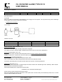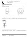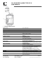
1
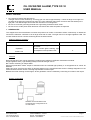
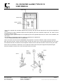
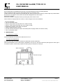
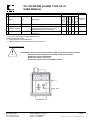
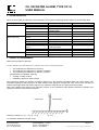
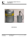
OIL ON WATER ALARM, TYPE OF-10
USER MANUAL
Au service de l’eau
USER MANUAL
ISMA
Rue Hector Malot
Tél : 03.87.87.62.16
Fax : 03.87.88.18.59
57600 FORBACH – France
E-mail : [email protected]
Internet : www.isma.fr
Page 1
OF-10-Notice de mise en service et maintenance ANGLAIS 210499
OIL ON WATER ALARM, TYPE OF-10
USER MANUAL
Au service de l’eau
CONTENTS
Safety cautions.......................................................................................................................................... page 1
1. General.................................................................................................................................................. page 1
2. Operation .............................................................................................................................................. page 1
2.1. Functions of switches.................................................................................................................... page 2
2.2. Startup procedure ......................................................................................................................... page 2
2.3 Window glass cleaning .................................................................................................................. page 3
2.4. Light axis adjustment .................................................................................................................... page 4
2.5. Operation check ............................................................................................................................ page 5
2.6. Shutdown ...................................................................................................................................... page 6
3. Maintenance.......................................................................................................................................... page 6
3.1. Maintenance schedule .................................................................................................................. page 6
3.2. Desiccant replacement ................................................................................................................. page 6
3.3. Fuse replacement ......................................................................................................................... page 7
4. Troubleshooting .................................................................................................................................... page 7
5. Principle of measurement ..................................................................................................................... page 7
6. Installation ............................................................................................................................................. page 9
6.1. Example of installation ................................................................................................................ page 10
6.2. Sitting requirements .................................................................................................................... page 10
6.3. Installation practice ..................................................................................................................... page 11
6.4. Piping connections ...................................................................................................................... page 12
6.5. Electrical connections ................................................................................................................. page 13
7. Standard specifications ....................................................................................................................... page 17
ISMA
Rue Hector Malot
Tél : 03.87.87.62.16
Fax : 03.87.88.18.59
57600 FORBACH – France
E-mail : [email protected]
Internet : www.isma.fr
Page 2
OF-10-Notice de mise en service et maintenance ANGLAIS 210499
OIL ON WATER ALARM, TYPE OF-10
USER MANUAL
Au service de l’eau
SAFETY CAUTIONS
Do not directly stare at the light source:
The light source is near infrared ray. Its energy per unit area is approximately 1.2 times as large as sun light. Do
not stare at the light source and do not place any mirror reflection object (such as mirror and wrist watch) in the
light path. The reflected light from water and oil surface is not dangerous.
Be sure to round the grounding terminal with a grounding resistance below 100Ω.
Be sure to turn off the power when electrical connections are made and parts are replaced
1. GÉNÉRALITÉS
This equipment is the sensor/alarm to monitor the presence of oil film on the water surface continuously. It utilizes the
fact that the reflection coefficient of oil is larger than that of water. The light source is the high brightness LED. The
monitor features the non-contact monitoring above the water surface.
Outline of start up procedure
Step
Description
reference
Installation
Mounting and wiring of sensor and
transmitter.
Perform window glass cleaning, light
axis adjustment and operation test.
6.
Operation
2.
Routine run
Features
almost all species of oils can be detected by employing the reflection coefficient measurement method.
A high brightness LED ( Light Emitting Diode) is used as the light source.
Non-contact monitoring of sample water.
Sensing-impracticable contact output is delivered when the reflected light quantity is so dropped that oil cannot be
detected.
Peak hold circuit: free from the effect of dust that passes on the monitored water surface. Garbage stagnation on the
monitored water surface causes a sensing-impracticable contact output.
Besides the oil film sensing contact signal, oil film generation can be recorded by connecting a recorder to the output.
System configuration
Transmitter
sensor
Standard accessories Refer to the
accessories list. Configuration of oilon-water alarm
ISMA
Rue Hector Malot
Tél : 03.87.87.62.16
Fax : 03.87.88.18.59
57600 FORBACH – France
E-mail : [email protected]
Internet : www.isma.fr
Page 3
OF-10-Notice de mise en service et maintenance ANGLAIS 210499
OIL ON WATER ALARM, TYPE OF-10
USER MANUAL
Au service de l’eau
2. OPERATION
2.1. function of switch
Green zone
Power indicator
Meter
Gain control used for
sensitivity adjustment
(reflected light level of
water adjustment)
Fuse
Power switch
CHECH-MEASURE
switch*
*turned to CHECK when light axis is adjusted, and the peak hold function is released. And the indication largely
fluctuates by ripples on water surface. Be sure to turn this switch to MEASURE when in measurement. When the
switch is in CHECK position, the transmission signal drops about 4mA delivering a Sensing-impracticable contact
output.
2.2. Names and functions of switches
Confirm the installation is completed before starting operation. If not complete, follow the procedure of section 6.
confirm that the following requirements are met
•
•
•
•
•
•
•
•
•
In the case of the stationery type, the distance between the low end of monitor and the water surface shall be
0.5m.
Air piping must be properly made for air purge and air curtain.
sensor extension cable, power line and signal output line cable must be correctly connected.
For air purge, provide an instrument air stream for approximately 30 minutes. This is to clean the transmitter
inside.
Clean the window glass.
Remove the cover and supply power and turn the power switch to ON.
Perform light axis adjustment
Confirm that the transmitter cover is attached.
Confirm the transmitter operation. Now the monitor is in routine run.
ISMA
Rue Hector Malot
Tél : 03.87.87.62.16
Fax : 03.87.88.18.59
57600 FORBACH – France
E-mail : [email protected]
Internet : www.isma.fr
Page 4
OF-10-Notice de mise en service et maintenance ANGLAIS 210499
OIL ON WATER ALARM, TYPE OF-10
USER MANUAL
Au service de l’eau
2.3. Window glass cleaning
Cover
Cover removal
Window
glass
Dust or garbage on the window glass drops the sensitivity and reduces the ability of oil film sensing. Periodically clean
the glass.
Clean with gauze soaked with alcohol, then finish with dry gauze.
Increase the maintenance frequency in early spring accompanied by strong wing and in rainy season of high humidity.
When the window glass is frequently fouled, apply air curtain (optional). (refer to 6.4.)
2.4. Light axis adjustment
Light axis deviation drops the signal level leading to oil film sensing impracticability.
When the indication is always below 25% of fullscale, and window glass cleaning cannot restore the sensing
capability, perform light axis adjustment.
Perform light axis adjustment on a day of no wind and no ripples on the water surface by a method which does not
make ripples.
Caution
Perform this adjustment after confirming that no oil film is present on the water surface.
[adjustment procedure]
First, confirm that the distance between the low end of the sensor and the monitored water surface is 0.5m.
Remove the transmitter cover and turn the CHECK-MEASURE switch to CHECK.
Adjust the direction of the sensor as shown the following a), b), and c) to find the point where the meter reads the
maximum value (approximately 30% of fullscale).
Note: When there are ripples on the water surface to be monitored, generated waves can be partly eliminated by
immersing the supplied wave protector assembly by about ½.
ISMA
Rue Hector Malot
Tél : 03.87.87.62.16
Fax : 03.87.88.18.59
57600 FORBACH – France
E-mail : [email protected]
Internet : www.isma.fr
Page 5
OF-10-Notice de mise en service et maintenance ANGLAIS 210499
OIL ON WATER ALARM, TYPE OF-10
USER MANUAL
Au service de l’eau
Green zone
GAIN control
Switch of (check
measure)
Light axis is adjusted with front/back adjust bolts (2 pieces) and right and left adjust bolt of the light axis adjustment
section.
By loosening the upper front/back adjust bolt and tightening the lower front/back adjust bolt, the sensor moves
backward, and vice versa.
By loosening upper right/left adjust bolt and tightening the lower right/left adjust bolt, the sensor moves leftward, and
vice versa.
On completion of adjustment, fasten the sensor by tightening four adjust bolts.
Turn the CHECK-MEASURE switch to MEASURE.
Note: The switch must be turned to MEASURE during operation. If turned to CHECK, oil film cannot be detected.
after about 20 seconds, confirm the meter pointer is within the green zone. If the indication deviates from the green
zone between 25≅28% or between 32≅35% adjust the GAIN control so that the indication comes into the green zone.
Notes: when the indication is below 25%, do not adjust the GAIN control but perform light axis adjustment again.
when the indication is above 35%, check the water surface for oil film.
sensor
sensor
Wave
protector
assembly
sensor
sensor
ISMA
Rue Hector Malot
Tél : 03.87.87.62.16
Fax : 03.87.88.18.59
57600 FORBACH – France
E-mail : [email protected]
Internet : www.isma.fr
Page 6
OF-10-Notice de mise en service et maintenance ANGLAIS 210499
OIL ON WATER ALARM, TYPE OF-10
USER MANUAL
Au service de l’eau
2.5. Operation check
Produce an oil film on the water surface.
Heavy oil A is suitable for this purpose because it forms oil film rapidly and the film can be easily seen.
ISMA
Rue Hector Malot
Tél : 03.87.87.62.16
Fax : 03.87.88.18.59
57600 FORBACH – France
E-mail : [email protected]
Internet : www.isma.fr
Page 7
OF-10-Notice de mise en service et maintenance ANGLAIS 210499
OIL ON WATER ALARM, TYPE OF-10
USER MANUAL
Au service de l’eau
Caution
Such oil that does not spread as the film has a not horizontal surface which is hardly detected.
When it is difficult to drip oil on the actual water surface for operation check.
Confirm that the oil film passes the point beneath the sensor and the oil film sensing contact output is provided within
20 seconds. This signal is reset 15≅40 seconds after disappearance of the oil film.
Short term shutdown
Short term shutdown completes merely by turning the power switch to OFF.
Note: Continue air purge and/or air curtain, if used, during the short term shutdown.
Long term shutdown
• Turn off the power switch.
• Stop air purge (when air purge and or air curtain is used)
• Stop air curtain (when air purge and or air curtain is used)
• Restarting procedure in this case is as follows:
• Clean the window glass of sensor.
• Provide instrument air flow for about 30 minutes (when air purge and/or air curtain is used).
• Turn on the power switch.
3. MAINTENANCE
3.1. Maintenance schedule
Perform maintenance as follows for stable use of OF-10.
3.2. Desiccant replacement
Insulation drop due to humidity rise within the transmitter causes malfunction.
When the transmitter cover is removed for maintenance, be sure to check the desiccant (silica gel).If the silica gel is
not effective (when coloured red), replace the silica gel by a fresh pack of silica gel.
Back of transmitter
Desiccant silica gel
ISMA
Rue Hector Malot
Tél : 03.87.87.62.16
Fax : 03.87.88.18.59
57600 FORBACH – France
E-mail : [email protected]
Internet : www.isma.fr
Page 8
OF-10-Notice de mise en service et maintenance ANGLAIS 210499
OIL ON WATER ALARM, TYPE OF-10
USER MANUAL
Au service de l’eau
1 Window glass
Cleaning
2 Light
axis Adjustment
adjusting section
3 desiccant
replacement
Remove fouling
Adjust the rtimpot at a point where the meter pointer deflects the max. value.
Adjust sensitivity too if necessary
Replace the desiccant inside the
equipment
As
required
A year
Description
A month
Item
2 weeks
Object
Control period
Initial
operation
Maintenance object
Reference
item
2.3
2.4
3.2
: check for abnormality. Perform specified work.
Make specified adjustment.
: make cleaning of specified places.
: replace specified part for maintaining the performance.
3.3. Fuse replacement
!
ATTENTION : When the fuse has been blown, replace it by the following procedure.
Shut off the power input (but not turning off the power switch).
Remove the cause of the trouble.
Replace the fuse by a new one.
Put the fuse cap as it was and supply the power.
Fuse 1 A
Power switch
ISMA
Rue Hector Malot
Tél : 03.87.87.62.16
Fax : 03.87.88.18.59
57600 FORBACH – France
E-mail : [email protected]
Internet : www.isma.fr
Page 9
OF-10-Notice de mise en service et maintenance ANGLAIS 210499
OIL ON WATER ALARM, TYPE OF-10
USER MANUAL
Au service de l’eau
4. TROUBLESHOOTING
When an abnormality of indication of the transmitter is encountered, take appropriate actions by the following table.
Symptom
Unstable indication
Cause
Fouled window
Light axis deviation
High ripples on water surface
Remedy
Clean the window glass
Light axis adjustment
Remove ripples. Select a
rippleless place.
Abnormal electric circuit
Contact agent
Insulation drop
Desiccant replacement
No
indication Obstacles and whirl on water Remove them.
(abnormally low)
surface
Light axis deviation
Light axis adjustment
Fouling on glass window
Window glass cleaning
Dewing on window glass
Perform air curtain
Water vapour on water Glow off the vapour without
vapour
producing ripples
Abnormal electric circuit
Contact agent
Insulation deterioration
Desiccant replacement
Power is not supplied
Blown fuse
Fuse replacement
Power failure
Supply electricity
Reference
2.3
2.4
3.2
2.4
2.3
6.4
3.2
3.3
5. PRINCIPE OF MEASUREMENT
Method and principle of detection
Various methods of oil film detection are available. They can be classified as follows
• The method by the difference in buoyancy
• The method by the difference in reflection coefficient
• The method by the difference in dielectric constant
[classification by installation method]
• Floating on water surface
• Installation apart from water surface
This equipment utilizes the reflection coefficient difference by the equipment installed apart from water surface. We
frequently experience that the oil film on water surface looks glaring in everyday life. This is due to the fact that oil
reflects visible light better than water; that is to say, reflection coefficient of oil is larger than that of water.
When the incident light comes to the boundary surface of two substances with different reflection coefficient, the
reflection coefficient is calculated as follows:
Incident light
reflection coefficient = [ (n1 – n2 )/ (n1 + n2 )]²
Reflected light
(n > n2)
n1: reflection coefficient of water, oil etc.
ISMA
Rue Hector Malot
Tél : 03.87.87.62.16
Fax : 03.87.88.18.59
57600 FORBACH – France
E-mail : [email protected]
Internet : www.isma.fr
Page 10
OF-10-Notice de mise en service et maintenance ANGLAIS 210499
OIL ON WATER ALARM, TYPE OF-10
USER MANUAL
Au service de l’eau
n2: reflection coefficient of air
Reflection coefficients of various liquids are as listed in the following table. Oils are not pure substance and their
reflection coefficients have some ranges. The list gives approximate values. As know from these values:
reflection coefficient of water surface: 2%
reflection coefficient of oil film: 3≅4%.
Then the reflection coefficient exhibits an increase of 50≅100% by the presence of oil film. Therefore, when the water
surface is irradiated by a light of constant intensity such as laser beam, oil film can be detected by the intensity
difference of reflected light.
Reflection coefficient of various liquids
Substance
Air
Water
Gasoline
Kerosene
Gas oil
Heavy oil
Benzene
Toluene
N
1.00
1.33
Above 1.40
Above 1.45
1.45≅1.50
Above 1.45
1.50
1.50
Substance
Xylene
Paraffine oil
Linseed oil
Olive oil
Coconut oil
Soybeen oil
Whale oil
Cod liver oil
N
1.50
1.48
1.48
1.47
1.45
1.47
1.47
1.48
Generally, the detection limit of oil film can be visually recognized. The film thickness is not more than 1µm, and the
reflected light intensity does not increase with the increase of thickness but keeps a constant reflected light intensity.
As shown in the above table, almost all oils have a reflection coefficient above 1.40. therefore, oil film detection is
possible if only a smooth oil film can be formed.
The light of LED pulse-modulated by the modulation circuit passes the collimate lens forming a light beam to irradiate
the water surface to be monitored.
The reflected light from the monitored water surface enters the light receiver through the condenser lens. The light is
amplifier and the band pass filter to remove disturbance components. The signal component alone enters the peak
hold circuit to keep each peak value for about 16 seconds.
When the hold value rises above about 150% of the stationary water level (above 45% FS in meter reading), an oil film
sensing contact output is delivered.
System diagram
ISMA
Rue Hector Malot
Tél : 03.87.87.62.16
Fax : 03.87.88.18.59
57600 FORBACH – France
E-mail : [email protected]
Internet : www.isma.fr
Page 11
OF-10-Notice de mise en service et maintenance ANGLAIS 210499
OIL ON WATER ALARM, TYPE OF-10
USER MANUAL
Au service de l’eau
When the hold value drops below about 67% (below 20%FS in meter reading) by some reason (large waves,
obstacles, vapour on water surface, dewing on window glass etc.), and this condition lasts for about one minute, a
sensing-impracticable contact output is delivered.
ISMA
Rue Hector Malot
Tél : 03.87.87.62.16
Fax : 03.87.88.18.59
57600 FORBACH – France
E-mail : [email protected]
Internet : www.isma.fr
Page 12
OF-10-Notice de mise en service et maintenance ANGLAIS 210499
OIL ON WATER ALARM, TYPE OF-10
USER MANUAL
Au service de l’eau
6. INSTALLATION
6.1. Example of installation
An installation example using the pole stand (optional) and hanging arm (optional) is a shown below.
6.2. Sitting requirements
The place of installation should meet the following requirements.
Sensor installation requirements
Mild ripples:
High ripples and whirls on the water surface to be monitored may cause reduction of reflected light which leads to loss
of sensing ability. Strong rain on the water surface to prevent direct exposure of the water surface to rain.
Note: When the reflected light quantity drops to a value which can not be detected, and the condition lasts for about
one minute, a sensing-impracticability contact signal is delivered.
Minimum water level variation:
When the light axis is adjusted with 0.5m of the distance between the sensor bottom end and the water surface,
sensing is possible for water level variation of ±0.2m (0.3m≅0.7m), but use the monitor at a place of minimum level
variation.
Note: Only when there is a slow undulation on the water surface to be monitored, oil film can be detected within
0.3≅1m range of distance between the sensor bottom end and the water surface. In this case, however, adjust the light
axis for 1m of the distance. If the light axis for 1m of the distance. If the light axis adjustment is made for a distance
over 1m, a malfunction will result.
No water vapour generation on the water surface:
water vapour on the water surface causes light scattering and dewing on the window glass disturbing oil film detection.
A sensing-impracticable contact output is delivered in this case.
Notes:
When water vapour is present on the water surface, send wind which does not cause ripples to blow off vapour.
To prevent dewing on the window glass, apply air curtain (optional) to the sensor
In the rainy season, the use of air curtain is recommended from the beginning since dewing is apt to occur on the
glass.
Installation practice
Minimum corrosive gas and dust
Minimum vibration and impacts
No nearby inductive equipment and welders
ISMA
Rue Hector Malot
Tél : 03.87.87.62.16
Fax : 03.87.88.18.59
57600 FORBACH – France
E-mail : [email protected]
Internet : www.isma.fr
Page 13
OF-10-Notice de mise en service et maintenance ANGLAIS 210499
OIL ON WATER ALARM, TYPE OF-10
USER MANUAL
Au service de l’eau
Dimensions
Cable
Cable out let
Air inlet
Air outlet
Air inlet
installation of stationary type equipment refer to the installation example and dimensions for actual installation.
Adjust the distance between the sensor bottom end and the water surface at 0.5m. the adjustment of the distance is
made by loosening holder tightening bolts and moving the sensor pole up and down. when up and down motion of the
pole is insufficient for adjustment, adjust the pole base mounting position of the hanging arm.
Mount the transmitter on the pole base and fasten it with the lock screw.
Route the extension cable after adjusting the distance between the bottom end of sensor and the water surface.
Considering the convenience of sensor removal. Secure a cable sag at the cable outlet of sensor pole, and between
the hanging arm and the pole base.
other details
connect a conduit to the cable port at the top of the sensor to mount the sensor almost upright.
The distance between the bottom end of sensor and the water surface should be 0.5m.
To perform light axis setting, secure the light axis adjusting function that allows directional change in two directions by
about ±2° against the vertical line.
Erect a 50A steel pipe at a place which meets requirements, and mount the transmitter on the pipe.
ISMA
Rue Hector Malot
Tél : 03.87.87.62.16
Fax : 03.87.88.18.59
57600 FORBACH – France
E-mail : [email protected]
Internet : www.isma.fr
Page 14
OF-10-Notice de mise en service et maintenance ANGLAIS 210499
OIL ON WATER ALARM, TYPE OF-10
USER MANUAL
Au service de l’eau
6.4. Piping connections
when there is high humidity, corrosive gas and dewing on the window glass, apply air purge and air curtain (optional)
with dry air to the system.
Air purge of transmitter
Connect a Ø4x Ø6mm nylon tube to the air inlet (half union) on the bottom surface of transmitter to supply dry air. Dry
air: instrumentation air or equivalent
Pressure: 0.4kg/cm²G
Flow rate: 2Nl/min
!
caution
Never supply air to the system unless specifications include air purge.
Air pressure may cause damage to the system since the air outlet is blocked.
Air curtain of sensor
Supply dry air to the air inlet of the sensor using the nylon tube of Ø2.4x Ø3.2mm and joint designated in air curtain
specifications.
Dry air: Instrument air or equivalent
ISMA
Rue Hector Malot
Tél : 03.87.87.62.16
Fax : 03.87.88.18.59
57600 FORBACH – France
E-mail : [email protected]
Internet : www.isma.fr
Page 15
OF-10-Notice de mise en service et maintenance ANGLAIS 210499
OIL ON WATER ALARM, TYPE OF-10
USER MANUAL
Au service de l’eau
Pressure: Set as shown in the table according to the length of Ø2.4x Ø3.2mm tube.
Tube length vs. pressure.
Tube length (m)
Supplied pressure (kg/cm²)
2
0.1
4
0.2
6
0.3
8
0.4
10
0.5
Flow rate: 5nl/min
CAUTION
When air curtain is not include in specifications, never supply air to the system. The air pressure may cause a damage
to the system since the air curtain port is blocked.
6.5.Electrical connections
Cable routing
Cables to be used
Name of line
Power input line
Output line
Contact output line
Cable species
CV V 0.5~1.25mm²
CV VS 0.5~1.25mm²
CV V 0.5~1.25mm²
Cores
2~3
2
As required
Overall diameter
12mm
12mm
12mm
Sensor extension cable (terminals: 1~7)
The sensor end of the cable is already wired before shipment
The cable must have a margin length considering the need for sensor removal in maintenance.
Power line (terminal No: 90, 91, E)
supply a power source, like the commercial power source, whose common side is grounded.
Supply the power from a power line other than that for power consuming equipment.
Grounding line (grounding terminal E)
be sure to ground with a grounding resistance below 100Ω.
Use a 3-core power line cable, and ground the third wire at the distribution board.
Connect the grounding line to the ground other than that of power consuming equipment.
Output line (terminals: 70,71)
the output is about 4mA with no reflected light and about 8.8mA with reflected light from stationary water surface.
Make electrical connections as required.
Ground the shielding of the cable at the receiver side.
4-20mADC, max. load 600Ω (isolated type)
oil film sensing contact output line (terminal: 30,32)
When the reflected light quantity rises above 150% (about 45% of meter scale) of the stationary water level, a contact
output is delivered within 20 seconds.
ISMA
Rue Hector Malot
Tél : 03.87.87.62.16
Fax : 03.87.88.18.59
57600 FORBACH – France
E-mail : [email protected]
Internet : www.isma.fr
Page 16
OF-10-Notice de mise en service et maintenance ANGLAIS 210499
OIL ON WATER ALARM, TYPE OF-10
USER MANUAL
Au service de l’eau
Contact capacity: 125VAC 0.2A or 30VDC 1A (with resistive load)
Note: The oil film sensing contact output is delivered even when the power is OFF.
Sensing-impracticable contact output line (Terminals: 33~35). When the reflected light quantity drops below about
67% (about 20% of the meter) of the stationary water level, and that condition lasts for more than one minute, an
alarm signal is delivered.
Contact capacity: 125VAC 0.2A or 30VDC 1A (with resistive load)
ISMA
Rue Hector Malot
Tél : 03.87.87.62.16
Fax : 03.87.88.18.59
57600 FORBACH – France
E-mail : [email protected]
Internet : www.isma.fr
Page 17
OF-10-Notice de mise en service et maintenance ANGLAIS 210499
OIL ON WATER ALARM, TYPE OF-10
USER MANUAL
Au service de l’eau
Note: The sensing-impracticable contact output is delivered when the transmitter check switch (CHECK-MEASURE) is
in check and when the power supply is shut off.
CAUTION
When an inductive load is connected to the sensing-impracticable contact output, be sure to insert a surge absorber in
the load side for contact protection.
couvercle
make connections to each terminal blocks of the transmitter by the following procedure:
remove the gland to open the transmitter interior to the atmosphere.
As shown above, move the cover by the numeric order in arrow directions to remove the cover.
Introduce each cable into the transmitter via gland. Tighten each gland securely to guarantee air lightness of the
transmitter
CAUTIONS
be sure to turn off the power source whenever connections are made.
The use of lightning protector is recommended to the power line and output line prevent the damage due to
thunderbolt.
ISMA
Rue Hector Malot
Tél : 03.87.87.62.16
Fax : 03.87.88.18.59
57600 FORBACH – France
E-mail : [email protected]
Internet : www.isma.fr
Page 18
OF-10-Notice de mise en service et maintenance ANGLAIS 210499
OIL ON WATER ALARM, TYPE OF-10
USER MANUAL
Au service de l’eau
7. STANDARD SPECIFICATIONS
Oil on water alarm
OF 10
Floating oil film on water
Reflection coefficient measurement by near infrared beam
Near infrared LED
Approx. 2mW
Approx. 20mm² with 0.5m if sensing
Distance (approx. Ø5mm)
Within 20 sec (the time from oil film sensing to alarm
output)
Temperature -5~50°C
Humidity 85%RH max.
No freezing, no water vapour generation (contact DKK
when vapour is generated)
4-20mADC (max. load 600Ω), isolated I/O (approx. 8.8mA
for reflected light on stationary water)
Oil film sensing contact output
Contact capacity 125VAC 0.2A (resistive load) or 30VDC
1A (resistive load)
100VAC±10% 50/60Hz
110VAC±10ù 50/60Hz (optional)
Approx. 5VA
Air purge for transmitter (optional); joint for Ø4x Ø6mm
resin tube, dry air (instrument air or equivalent)
0.4kg/cm²G, approx. 2N/min
Air curtain for sensor (optional); R (PT) ¼ , dry air
(instrument air or equivalent) 0.1~0.5kg/cm²G, 5nl/min
Rainproof (transmitter and sensor)
Indicator/transmitter; 50A pole mount (optional)
Indicator/transmitter
ABS resin and AC7A (corrosion resistant cast aluminium)
Indicator/transmitter, Ø170x300m
Sensor Ø112x242mm
Product name
Model
Measurement object
Measurement method
Light source
Light output
Monitoring area
Response time
Ambient conditions
Sample temperature
Output
Alarm contact
Power requirements
Power consumption
Air
Construction
Mounting
Materials
Dimensions
ISMA
Rue Hector Malot
Tél : 03.87.87.62.16
Fax : 03.87.88.18.59
57600 FORBACH – France
E-mail : [email protected]
Internet : www.isma.fr
Page 19
OF-10-Notice de mise en service et maintenance ANGLAIS 210499
OIL ON WATER ALARM, TYPE OF-10
USER MANUAL
Au service de l’eau
Refer to drawing of dimensions
Indicator/transmitter; approx. 4kg
Sensor: approx 2kg
Indicator/transmitter: metallic silver, lemon yellow
Sensor metallic silver
Waterway wall, bridge on waterway, manhole (resistant to
direct sun light)
0.5±0.2m (bottom end of monitor to water surface), only
when light axis is set at 0.5m of the distance.
Gland for Ø12mm cable (3 pcs)
Gland for Ø5mm cable (1pc)
(for extension cable)
Dedicated cable for connection between sensor and
transmitter
10m (standard)
Weight
Paint colour
Installation conditions
Water surface distance
Cable connection port
Extension cable
Extension cable length
ISMA
Rue Hector Malot
Tél : 03.87.87.62.16
Fax : 03.87.88.18.59
57600 FORBACH – France
E-mail : [email protected]
Internet : www.isma.fr
Page 20
OF-10-Notice de mise en service et maintenance ANGLAIS 210499