1
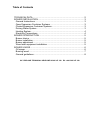
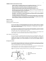
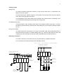
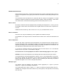
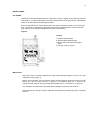
JASPI DUO 1, 2 & Solar
Multifuel boilers
INSTALLATION AND
USER MANUAL
WWW.JASPI.UK
JASPI KNOWS HEATING
Table of Contents
TECHNICAL DATA ......................................................................................2
BOILER INSTALLATION .............................................................................3
General Instructions ..................................................................................3
Open Expansion Container Systems .........................................................3
Coated Expansion Container Systems ......................................................3
Driving Water System................................................................................3
Heating System ......................................................................................... 4
Electricity Connections ..............................................................................4
BOILER INTRODUCTION ...........................................................................5
Burner choice ............................................................................................5
Burner installation......................................................................................5
Burner adjustment .....................................................................................5
Wood side equipment installation ..............................................................5
BOILER USAGE ..........................................................................................6
Oil usage ...................................................................................................6
Burning wood ............................................................................................7
General guidelines ....................................................................................8
UK / IRELAND TECHNICAL HELPLINE 01392 247 343 IRL +44 1392 247 343
2
Figure 1. JASPI-DUO 1 and JASPI-DUO 2 boiler standard equipment:
- Domestic hot water coil (flange)
- combined mano-thermometer
- cleaning equipment set
- Termomix mixing valve R 1"
- draft control R 3/4"
- chimney extension liner
- grate
- adjustment plate
- electric immersion heater
PARTS:
1. Domestic hot water out
ø22 mm
2. Cold water in
ø22 mm
3. Boiling aggregate (output to accum.)
R1
4. Expansion aggregate (return from acc.) R 1
5. Draft regulator aggregate
R 3/4"
6. Fire management hatch
7. Air valve (primary air)
8. Filling hatch
9. Air valve (secondary air)
10. Cleaning hatch
11. 12. Drain
13. Burner hatch
14. Flame observation glass
15. Cleaning hatch
16. Analysis hole
17. Mixing valve
R 3/4"
18. Heating output
19. Heating return
20. Adjustment panel
21. Burner thermostat
22. Immersion heater thermostat
23. Thermometer
24. Manometer
25. Wood loading hatch
255 x 100 mm
26. Leg
27. Sensor connection for TSK valve R 1/2"
Model
JÄSPIDUO 1
DUO 1 S
DUO 2
DUO 2 S
Boiler measures (mm)
H
A
B
C
1420
1420
1420
1420
720
720
720
720
610
610
760
760
955
955
955
955
Wood chamber meas. (mm)
Width
Depth Height
250
250
250
250
380
380
530
530
700
700
700
700
oil
Output (kW)
Water Wght.
wood electr. sp. (L) (kg)
20
20
25
25
20
20
25
25
6
6
160
160
235
235
300
300
365
365
Technical data:
Recommend. accumulator:
Recommend. chimney:
3
0,5,,,2,5 m (e.g. JÄSPI-GTV-500)
2
brick ~ 250 cm
steel ø150 mm
Recomm. chimney height:
min. 5 metres
Hot water coil:
200 l/40 °C/10 min. (Duo-1)
200 l/45 °C/10 min. (Duo-2)
Structural pressure:
1,5 bar
Max temperature in usage: 100 °C
ASSURANCE OF CONFORMITY WITH EC-STANDARDS
This assurance applies to our manually-operated boilers functioning on solid fuel: JÄSPI Tupla, Triplex, ECOPUU, YPV 40.
We assure that the abovementioned aggregata are in conformance with the essential safety requirements of the EC
directive 97/23/EC, article 3, subsection 2.3.
The fulfilment of the essential safety requirements, found in the directive appendix 1, articles 2.10, 2.11, 3.4 and section 5,
subsection a) and d) is clarified in the aggregata’s usage and installation instructions.
The manufacturing of the aggregata is done in accordance with good engineering practices.
In Raisio, Finland 5.6.2002
Raimo Aaltonen
General Manager
3
GENERAL INSTALLATION INSTRUCTIONS
Install the boiler in an upright position on an incombustible surface in a dry boiler room.
Observe sufficient installation and maintenance space around the boiler.
Boiler connections to the network are done so that the piping is not strained.
Install necessary lock valves in the network for maintenance purposes.
During the network pressure test the boiler pressure must not exceed 1,5 bar.
After filling, the pipe connections and sealing are carefully checked to avoid damage to the
boiler and electric appliances from a possible leak.
The free combustion air opening, that is lead to the boiler room, should be at least the size
of the chimney aperture (150 mm x 150 mm).
The boiler is connected to the chimney with the chimney extension liner (standard
equipment). Joints must be carefully compressed with mineral wool, fibre glass braid or
equivalent to avoid the weakening of traction.
The distance between the boiler and the duct can be up to several metres. In that case the
connecting pipe should be in a horizontal or rather ascending position and the cross-section
must conform to chimney recommendations. The pipe should be isolated and the joints
sealed. Possibility to sweep the chimney should also be ensured.
-
-
INSTALLATION
Expansion system
Coated expansion container system
On top of the boiler in the boiling aggregate there should be a reliable (without a clamping
device) 1.5 bar safety valve whose blasting output should correspond to the amount of (water)
vapor that is produced at maximum output, 20 kW (Duo 1) / 25 kW (Duo 2). Use of two
safety valves is recommended.
The safety valve is installed unclamped to the boiler’s boiling aggregate. The valve’s exhaust
pipe should not be reduced from it’s nominal size and it should be directed thus, that the
discharged vapor does not damage people or property.
The active volume of the coated expansion boiler should be at least 5% of the facility’s total
water quantity. In practice it should be dimensioned according to at least 7%.
Open expansion container system
On top of the boiler an unlocked sleeve pipe should be led to the expansion container. The
container’s minimum volume must be 5% of the facility’s total water quantity. The container’s
overflow pipe should be mounted descending. The vapor discharge pipe should be
continuously ascending and it’s pate directed thus, that it does not damage people or
property.
Driving water system
The cold water pipe connected to the hot water coil is equipped with a valve group, including a
closing valve, a backlash valve and a 10 bar safety valve. The hot water thermostatic mixing
valve is mounted between the cold and hot water aggregates.
A boiling prevention valve must be connected to the hot water coil to block overheating when
wood is being burnt. Valve connection guidelines are shown in figure 2.
Figure 2. Connecting the boiling prevention valve (e.g. Jäspi-TSK) to the driving water coil.
1. Valve group
2. Boiling prevention valve
3. Sensor
4
Heating system
Mixing valve
The boiler’s standard equipment includes a 4-way mixing valve which is connected to the
flange on top of the boiler.
The pipe entering the radiator network is connected to the left (seen from the front) and the
return pipe to the right side of the valve.
The temperature of the outflow water that is needed in the network varies considerably. Thus
we recommend automating the functioning of the mixing valve.
Circulating water pump
The best location for the circulating water pump is the radiator network return pipe. To ensure
the pump’s good functioning, removing the accumulating air from the network should be taken
care of.
Energy accumulator
The boiler should be connected to an energy accumulator (with volume 500-2 500 litres) if
firewood burning is frequent. A reliable loading valve (e.g. Termovar 25) should be used in the
coupling which ensures that the returning water temperature does not fall below 60 °C.
Electricity connection
The boiler’s electricity connections must only be performed by a qualified electrician.
The connections are made according to the following scheme.
FEED 230-240V 1~ FROM MAINSWITCH OF HEATING ELEMENT
***6kW 30A 3x10mm°
**4kW 20A 3x6mm°
* 2kW 10A 3x1,5mm°
FEED FROM BURNER SWITC
MAX.240V/10A
S3
BURNER
CUT-OFF
THERMOSTAT
c
H
THERMOSTAT
12/U
22/V
c BURNER
THERMOSTAT
2000W
S2
2000W
S1
31/T
2,5mm°
2000W
IMIT 2
TG 1
*
21/S
CUT-OFF
THERMOSTAT
X1
4mm°
Signal lamp
1
10mm°
*11/R *
6mm°
N L1 1 2 3
X2
N L1
BURNER
6mm°
HEATING ELEMENT
(SPL 3x2kW 230V)
32/W
5
BOILER INTRODUCTION
When introducing the boiler, it should be ensured that the system is filled with water and air is
removed. The tightness of the piping should also be checked to avoid leaking damage to the
system.
The manometer must be observed in conjunction with the usage of the apparata. In coated
expansion container systems the pressure should be above 0,5 bar (but below 1,5 bar when
hot). Furthermore, check that the opening pressure of the safety valve is 1,5 bar.
Burner choice
All modern oil burners that are equipped with pre-heating and designed for 1.4-2.3 kg of oil/h,
are suitable. These values are reached at 0,5 US gall/h with a 60° nozzle when oil pressure is
6-14 bar.
Suitable burners include e.g. Oilon Junior Pro LJ 10, (LF-1) and Bentone B 10 FUV.
Burner installation
The burner can only be installed by a person qualified and entitled to the job.
An installation and usage manual is delivered with the boiler and it should be followed at all
times.
Burner adjustment
The exit gas values, required for burner adjustment, are measured from the analysis hole in
the duct connection piece. The analysis is taken on the first time of usage and the burner is
adjusted accordingly. Thus unnecessary smutting is avoided if ventilation is not sufficient. The
final adjustment is performed when boiler water reaches +75 °C.
In oil usage the adjusted values are appropriate when the smut value is 0-1 in the bachrah
scale, O2 % 3,5…4,5, CO2 > 12 % and CO < 30 ppm.
Once the burner is correctly adjusted, the boiler needs sweeping approx. once a year!
NOTICE! Incorrect burner adjustment can damage the burner hatch and exit gas controls.
In normal boilers the exit gas temperature is approx. 140 °C. If this temperature is too low for
the chimney material, the temperature can be raised by removing some of the hindermost
plates of the exit gas controls (nr. 4, figure 3) in the convection part. Removing one plate is
equivalent to approx. a 10 °C rise in exit gas temp erature.
Wood part gear
The traction control is installed in the traction control aggregate (nr. 5, figure 1) and the
damper (nr. 7, figure 1) according to instructions.
The cheek plate (only in Duo 2 boiler, nr. 7, figure 4) reduces the grate surface and it is
installed in a 45° angle to the boiler’s side on to p of the grate (to the right side, when looking
from the front).
6
BOILER USAGE
OIL USAGE
The burner control thermostat is set in the proximity of 75 °C or higher, thus producing more hot
driving water. Too low temperature in the boiler water (below 70 °C) will produce condensation
water on the fire surfaces and damage the boiler.
When heated with oil, the control thermostat of the electric immersion heater is set to 60 °C (in
Duo 1 S and Duo 2 S models). If the boiler has not been equipped with an electric immersion
upon delivery, it can also be installed later (contact manufacturer).
Figure 3.
Oil side
1. Oil side cleaning hatch
2. Wood/oil side cleaning hatch
3. Burner hatch with flame observation
glass
4. Exit gas control (1 piece)
Maintenance
When the burner is correctly adjusted, the boiler needs sweeping approx. once a year. (see
adjustment values, page 4).
Before the oil chamber can be cleansed, power must be switched off from the burner’s main
switch. Then the oil burner hatch (nr. 3, figure 3.) and cleansing hatch (nr. 1, figure 3) are
opened and the exit gas control, found behind the latter hatch, is removed (nr. 4, figure 3).
The chambers are cleansed by removing and extracting the smut from the surfaces.
After cleansing the exit gas control is replaced, the hatches are closed and power is switched
back on.
7
BURNING WOOD
JÄSPI-Duo operates with the top burning -principle and burning is enhanced with a patented
burning technique. Therefore the exit gases are cleaner and efficiency is higher. The boiler
can be most efficiently exploited by burning wood when connected to a 500-1500 litre
accumulator. Ideally the firewood should be approx. 30 cm (Tupla 1) or 50 cm (Tupla 2) long
with a diameter of 10-12 cm (cleaved).
Lighting
First ensure that the damper is in a horizontal position. Then the plate’s adjustment lever (nr.
11, figure 1) has been pushed back.
The fire is lit in the boiler with chips (on the bottom) and then firewood is added. Then the fire
control plate (nr. 3, figure 4) should be pulled in the front position and before closing the filling
hatch (nr. 5, figure 4.) it is pushed to the rear position with the cleansing stick.
(Fire can also be lit by filling the chamber with firewood and placing the chips underneath the
topmost wood. Then the fire control plate (nr. 3, figure 4) can already be pushed back.)
Adding firewood
Avoid unnecessarily opening of the filling hatch. Add firewood when the previous filling has
finished burning. The damper (nr. 10, figure 4) is closed before opening the filling hatch and
the fire control plate is pulled to the front position with the cleansing stick. When burning
wood, the fire control plate should be pushed back.
Burning air
To ensure good burning, it is important to burn with sufficient draft. Draft in the boiler is
adjusted with the draft adjuster thus, that draft in the charging space is sufficient to ensure
clean burning. It should also be made sure that secondary air is provided from the air valve
(nr. 6, figure 4). The valve should be approx. 5 mm open.
Figure 4.
Wood side
1.
2.
3.
4.
5.
6.
7.
8.
9.
10.
Cleaning hatch
Funnel
Fire control plate
Coal grating
Filling hatch
Air valve (secondary air)
Cheek plate on the right side 1 piece (only DUO 2)
Grate
Fire management hatch
Draft valve (primary air)
Cleansing
Cleansing the wood side is done from the front of the boiler. Most important is to keep
surfaces behind the cleansing hatch (nr. 1, figure 4) clean. The fire surfaces can be cleansed
by brushing and scraping off the accumulated smut through the cleansing and filling hatches.
8
Remove combustion residue through fire management hatch. Notice! The cleanness of the
boiler’s fire surfaces is important to keep the high efficiency.
GENERAL GUIDELINES
The water level indicator (manometer) should be checked regularly to ensure the sufficiency
of water in the system. Simultaneously it should be visually checked whether there are any
leaks in the piping.
The boiler can easily overheat in firewood use. This can cause the burner or immersion
temperature limiter to go off. Once the boiler has somewhat cooled off (temperature approx.
80 °C), the released temperature limiter can be retuned by pressing the temperature limiter
(nr. 21 / 24, figure 1) button (strongly pressing with a narrow-tipped stick) on the control panel.


![Manuel d`utilisation MRA 2 V1.2 240909.p[...]](http://vs1.manualzilla.com/store/data/006373886_1-5635bdf4271b517061cca2d643252436-150x150.png)