1
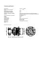
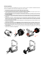
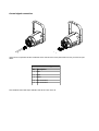
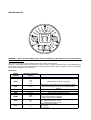
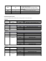
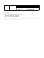
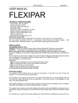
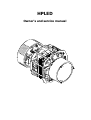
HPLED
Owner's and service manual
Read this manual totally and carefully follow all the instructions contained. File this manual for future use.
It is essential to read all the information contained to ensure installation, service and full operation of the
HPLed.
All operations must be accomplished, handled and carried out by qualified personnel only.
NOT COMPLYNIG WITH GIVEN NOTICE WILL VOID WARRANTY AND WILL FREE THE MANUFACTURER OF ANY SORT OF
RESPONSABILITY AND LIABILITY.
Unpacking
Unpack the carton and gently remove HPLed from the box. Ensure HPLed it's integer from origin in all its components.
In the event the HPLed shows any damage, do not use it and contact immediately your transporter as well your seller.
Items in the carton consist of:
–
HPLED Module
–
Rear metal cover with input connections
–
Blue Neutrik PowerCon connector
–
This owner's manual
Safety information
‒
‒
‒
‒
‒
HPLed must be installed on original “ ETC source 4” fixture only. Any other use will void warranty and will free
the manufacturer of any sort of responsibility and liability.
Minimum distance from any flammable source is of 0.5m.
Minimum throw distance from illuminated surface: 0.5m.
Power HPLed to safety circuit breaker.
Maximum ambient temperature: 35°C
Warning from electric shocks
All operations must be accomplished, handled and carried out by qualified personnel only.
‒
‒
‒
‒
‒
Disconnect power before servicing.
Do not handle HPLed with humid hands or near to any water or any kind of moisture sources.
IP20 protection rating.
HPLed is rated Class I.
Earth connection is mandatory.
CE Approvals
HPLed meets EMC 89/336/CEE, 92/31/CEE, BT72/23/CEE, 98/68/CEE requirements.
HPLed complies with EN50419 (Rohs) and 2002/96/EC (WEEE) norms.
Technical specifications
Power Supply
Maximum power consumption
cos Ø
Stand-by power consumption
Minimum ambient temperature
Maximum ambient temperature
LED Colour Temperature availability
LED CRI
LED Life (Manufacturer specification)
Weight
IP Rating
Working position
Power connectors
Data connectors
Data protocols
User interface
compliant
Dimensions (see picture)
100-240 V~ 50/60Hz
170W
0,98
5W
-10°C
35°C
2700°k,3000°K, 4000°K,5000°K (to specify when ordering)
Minimum 80 based on 2700°k, 3000°K, 4000°K models; Minimum
65 based on 5000°K
50.000 hours
2,03 Kg
IP20
Any
IN & OUT Neutrik PowerCon
IN & OUT XRL5
DMX 512; RDM
4-digit display and 4 buttons
HPLed installation
HPLED has been designed to be installed in any “ETC source 4” fixtures to give the equivalent of traditional HPL575/750
source. It is essential to remove some parts of existing “ETC source 4” fixture.
1. Disconnect any kind of power source that could cause electric shock
2. Loosen knobs that hold lens assembly, remove it and place it aside in a safe place
3. Locate rear section of the Source 4 fixture, then start loosening knob that hold the round plate in place until it is
totally separated from the main body. You may either store or scrap this part
4. As of now onwards for your own safety we recommend you must wear protection gloves and safety
transparent goggles.
5. Locate the Source 4 inner reflector and start removing it from its housing as shown in the Source 4 Assembly guide.
6. Place HPLed on working bench and start loosening the 3 M4 screws that hold the metal ring (marked by red arrow
in figure 2).
7. Insert HPLed in the Source 4 body ensuring the correct inward direction is followed as marked by the 2 red round
ring references and by the red arrow as shown in figure 3. During such operation make sure that the 3 connecting
cables (i.e. power cable, dmx cable and display cable) are led through loop-holes of the case ensuring that they will
not be squeezed during reassembling.
8. Remount the metal ring to its former position by tightening, the 3 provided M4x6 screws to their full extent. Do not
exceed nor force tightening.
9. Connect the 3 lead cables to the rear metal cover provided, ensure that connectors are inserted in the correct side.
Special attention must be given to the flat cable as it must be handled with extreme care while connecting its end.
10. Ensure that all cable connections are neatly and clearly cut set to there position avoiding any contact, interference,
interconnections, interpositions with fans and other interfering components that might collide, squeeze hamper the
correct operations.
11. Remount the rear metal cover to the Source 4 body using any 10mm spanner by tightening the screw to its full
extent. Do not exceed nor force tightening.
Fig.1
Fig.4
Fig.2
Fig.3
Fig.5
Connection to mains
WARNING ! Installation(s) must be accomplished, handled and carried out by qualified personnel only
and must comply with all norms in force in the installation's country
HPLed is supplied with a free Blue Neutrik PowerCon plug that must be wired using a 3x1.5mm² lead which additional
specifications include:
‒ Operating Voltage: 300/500V
‒ Test Voltage: 2KV
‒ Operating Temperature: -10°C / +90°C
Connect blue wire to N terminal, brown wire to L terminal and Yellow/Green wire to earth terminal. Ensure safety circuit
breaker at all times. Daisy chain of up to 10 units when connected to 230VAC. Daisy chain of up to 5 units when
connected to 110VAC. Maximum daisy chain length: 20m.
WARNING: HPLed CANNOT be powered by using an angle phase dimmer pack
Control signal connection
Fig.7
Fig.6
HPLed can be cooperated via either DMX512A and or RDM Protocols. Daisy chain DMX line using a-2 lead wire plus
shield.
DMX XLR 5 Pin Assignment
Pin Description
1
GND
2
DMX-
3
DMX+
4
Not connected
5
Not connected
Reed led blinks when DMX Input available. DMX off line when led is off.
HPLed Power ON
UP
ENTER
DOWN
ESC
WARNING ! Before powering HPLed ensure that all installation(s) procedure(s) have(s) been properly
set and accomplished.
When HPLed is powered the setup display will show the software release version.
Using the 4 UP ,DOWN, ENTER and ESC buttons, will be possible to operate the HPLed menu. UP and DOWN buttons
allows you to scan menu options, ENTER button to select and ESC button to back to previous menu option cancelling
the modification applied to the selected one.
Menu items
Display
Message
Addr
Mode
Allowed or displayed
values
001..510
2 ch
3ch
4ch
5ch
Man
0..255
drUt
LEdt
PUM
..°C
..°C
0..100%
GAMM
LInE
qUAd
booS
Off
on
PoS
AA
VV
Function
SetUp DMX Address
DMX Operating mode (see next page)
Manual light output adjust (possible if no DMX is present).
Adjusted value will be stored on the internal permanent
memory
Shows driver operating temperature
Show led operating temperature
Shows current led power (0-100%)
Dimmer profile selection:
- LinE for linear dimming regulation
- qUAd for tungsten lamp emulation
Boost selection:
off = maximum led power at 90%
on = maximum led power at 100%
Display orientation selection:
AA = normal
VV = inverted
Off
on
StbY
Standby display activity:
off = display always switched on
on = display switched off after few seconds of buttons
inactivity (only the right side dot will be lighted to indicate
DMX availability)
Off
on
..h ..
..h ..
dEF
TiML
TiMU
SoFt
ON Will restore the default factory values
Shows LED life
Shows HPLed life
Shows Software version
DMX Operating Modes (Mode)
HPLed provides different DMX operating modes ensuring the ideal use of the DMX universe
2ch Mode
Channel
1
2
3ch Mode
Channel
1
2
3
4ch Mode
Channel
1
Function
shutter
dimmer
Function
shutter
dimmer
Fan speed
Function
shutter
2
3
dimmer
Fan speed
4
Frequency
Modulation
5ch Mode
Channel
1
Function
shutter
2
3
4
Dimmer Coarse
Dimmer Fine
Fan speed
5
Frequency
Modulation
DMX Values
0-9
10..255
0..255
off
Strobe effect from slow to fast
Light output: 0=Off, 255=Maximum Power
DMX Values
0-9
10..255
0..255
0..24
24..255
off
Strobe effect from slow to fast speed
Light output: 0=Off, 255=Maximum Power
Fan at slowest speed
Fan speed from slow to fast
DMX Values
0..9
10..255
0..255
0..24
24..255
0..24
25..49
50..74
75..99
100..124
125..149
150..174
175..199
200..224
225..255
off
Strobe effect from slow to fast speed
Light output: 0=Off, 255=Maximum Power
Fan at slowest speed
Fan speed from slow to fast
PWM Frequency 1KHz
PWM Frequency 2KHz
PWM Frequency 3KHz
PWM Frequency 4KHz
PWM Frequency 5KHz
PWM Frequency 6KHz
PWM Frequency 7KHz
PWM Frequency 8KHz
PWM Frequency 9KHz
PWM Frequency 10KHz
DMX Values
0..9
10..255
0..255
0..255
0..24
24..255
0..24
25..49
50..74
75..99
off
Strobe effect from slow to fast speed
Light output: 0=Off, 255=Maximum Power – Coarse
Light output: 0=Off, 255=Maximum Power - Fine
Fan at slowest speed
Fan speed from slow to fast
PWM Frequency 1KHz
PWM Frequency 2KHz
PWM Frequency 3KHz
PWM Frequency 4KHz
100..124
125..149
150..174
175..199
200..224
225..255
PWM Frequency 5KHz
PWM Frequency 6KHz
PWM Frequency 7KHz
PWM Frequency 8KHz
PWM Frequency 9KHz
PWM Frequency 10KHz
Error messages
In case of malfunction, the following messages can be shown:
–
–
HP Fan Error: means problems on 40x40x10 fans
LED Fan Error: means problems on 80x80x10 fan
Should any of the above given messages occur, the LED will automatically switch off. Refrain and halt the use of the
HPLed and promptly contact any authorized service centre.
Periodic maintenance
To ensure the correct HPLed operation, we suggest the following periodic maintenance operations:
–
–
–
Remove dust or any kind of other dirty from the fans and loop-holes to ensure the correct air flow
Remove dust lenses using a cleaning cloth. This will ensure the maximum light efficiency
Replace damaged protection screen and lenses when necessary
Do not touch nor clean the LED as wll the yellow area around it with solvent
Device disposal information
At the end of its life, HPLed must be disposed to an appropriate electrical and electronic
equipment waste collection centre. Eco-friendly disposal, helps to avoid possible negative
impact on the environment and human health and promotes the reuse and/or recycling of the
materials making up the product. Illegal disposal involves administrative sanctions provided by
laws enacted.
Manufacture declines any sort of personal/corporate
responsibility/liability for damages caused by the
inadequate/misuse of the product as well as if the product has been handled by unqualified personnel. Not complying
with security norms/periodical maintenance as expressed in the owner's/service manual will also totally free
personal/corporate responsibility/liability.
Preliminary. Any changes can be brought without notice.
HPled 05/03/2013 rev.00-UK