1
INSTALLATION AND
OPERATION MANUAL
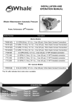
Whale® Watermaster® Automatic Pressure
Pump
s
Power, Performance Plu Protection
Model Number
Description
Marine Models
FW0814(B)
2.0 GPM (8 ltrs), 12 V d.c., 2 bar (30 psi), 15mm Quick Connect Connections
FW1214(B)
3.0 GPM (11.5 ltrs), 12 V d.c., 2 bar (30 psi), 15mm Quick Connect Connections
FW1225(B)
3.0 GPM (11.5 ltrs), 24 V d.c., 3 bar (45 psi), 15mm Quick Connect Connections
FW1215(B)
FT0814B
3.0 GPM (11.5 ltrs), 12 V d.c., 3 bar (45 psi), 15mm Quick Connect Connections
2.0 GPM (8 ltrs), 12 V d.c., 2 bar (30 psi), ½" NPT threaded connection
FT1214B
3.0 GPM (11.5 ltrs), 12 V d.c., 2 bar (30 psi), ½" NPT threaded connection
FT1225B
3.0 GPM (11.5 ltrs), 24 V d.c., 3 bar (45 psi), ½" NPT threaded connection
FT1215B
3.0 GPM (11.5 ltrs), 12 V d.c., 3 bar (45 psi), ½" NPT threaded connection
RV / Caravan Models
FP0814(B)
8 ltrs (2.0 GPM), 12 V d.c., 2 bar (30 psi), 12mm Quick Connect Connections
*The ‘B’ suffix indicates a bulk code is available
CONTENTS
Page 2
Page 8
Page 14
English
French
German
Page 20
Page 26
Page 32
Italian
Spanish
Swedish
Page 38
Finnish
ENG
INSTALLATION AND OPERATION MANUAL
Whale® Watermaster® Automatic Pressure Pump
Thank you for purchasing this Whale® product. For over 40 years, Whale® has led the way in the design and manufacture of
freshwater and waste systems including: pumps, plumbing, faucets and showers for low voltage applications. The company
and its products have built a reputation for quality, reliability and innovation backed up by excellent customer service.
For information on our full range of products visit www.whalepumps.com
1.
SPECIFICATION
Product Code
Voltage (V d.c.)
Open Flow Rate (per
min)
IP Rating
Recommended Fuse
Size (Amp Automotive)
Max Current Draw
(amps)
Minimum Wire Size
Weight
Cut Out Pressure
Inlet / Outlet Size
FW0814(B)
FW1214(B)
12
12
2.0 GPM
(8 ltrs)
Marine Models
FW1215(B)
12
3.0 GPM
(11.5 ltrs)
FW1225(B)
24
IP65
FT0814B
12
2.0 GPM
(8 ltrs)
Materials in Contact
with Fluid
Service Kits
Max. suction lift
Max. discharge head
7.5
7.5
5
4
6
6
3.5
4
6
6
3.5
1.5mm² (16 AWG)
1.5 kg (3.3 lbs)
3 bar (45psi)
2 bar (30psi)
2 bar (30psi)
1/2" NPT Threaded Connections
Glass-filled Polypropylene, Monprene®, Nitrile®, Stainless Steel
AK1316 - Replacement Head Kit
20m (66ft)
AK1317 - Microswitch Kit
3 m (9 ft)
30m (99ft)
20m (66ft)
RV / Caravan Models
AK1319 - Strainer
30m (99ft)
FP0814 (B)
12
Recommended Fuse Size
Current Draw
Weight
5 Amp Automotive
4 amps
1.6 kg (3.5 lbs)
2 bar (30psi)
Whale Quick Connect 12mm Female Connections
Inlet / Outlet Size
For 1/2” flexible hose use WU1282. For 3/8” flexible hose use WU1280
For Whale® Quick Connect 12mm no adapter required - use 12mm semi rigid pipework
WX7112
Glass-filled Polypropylene, Monprene®, Nitrile®, Stainless Steel
AK1317 - Microswitch Kit
SPECIFICATION
LIST OF CONTENTS
PRINCIPLES OF OPERATION
TO THE USER
TO THE FITTER
APPLICATION
AK1318 - Replacement Head Kit
1.5mm² (16 AWG)
AK1320 - Strainer
3m (9 ft)
20m (66ft)
Max. Suction Lift
Max. Discharge Head
1.
2.
3.
4.
5.
6.
3 bar (45psi)
Pump Body: Glass-filled Polypropylene, PBT (Polybutylene Terephylene)
Feet, Diaphragm & Valves: Monprene®, Seals: Nitrile®, Fasteners: Stainless Steel
Cut Out Pressure
LIST OF CONTENTS
3.0 GPM
(11.5 ltrs)
24
5
8ltrs (2.0 GPM)
2.
FT1225B
5
Open Flow Rate (per min)
Max. Wire Size
12
7.5
Product Code
Voltage (V d.c.)
Service Kits
FT1215B
7.5
*(B) suffix indicated pumps are available as a bulk or retail item.
Hose Connections
Semi Rigid Pipework System
Connections
Materials in Contact with Fluid
12
5
Whale® Quick Connect 15mm Female Connections
Materials
FT1214B
7.
8.
9.
10.
11.
12.
List of Diagrams
Fig. 1a
Marine Typical Installation
Fig. 1b
RV Typical Installation
Fig. 2
Pump Orientation
Fig. 3
Securing the Pump
WARNINGS
PARTS LIST
OPTIONAL EXTRAS
INSTALLATION
INSTRUCTIONS FOR USE
MAINTENANCE
Fig. 4
Fig. 5
Fig. 6
13.
14.
15.
16.
17.
18.
Connecting the Strainer
Pipework Connections
Wiring Diagram
WINTERIZING
TROUBLE SHOOTING
SERVICE SUPPORT DETAILS
PATENTS AND TRADEMARKS
WARRANTY STATEMENT
EU DECLARATION OF
CONFORMITY, STANDARDS AND
APPROVALS
3. PRINCIPLES OF OPERATION
The Whale Watermaster is an automatic pressure pump designed for recreational vessels or vehicles. The pump integrates
high specification motors and fully protected wiring to ensure reliability and a smooth consistent flow during use. Please refer
to the specifications (section 1) for the model range.
4. TO THE USER
Please read the following carefully before installation.
WARNING: Please note that incorrect installation may invalidate the warranty.
5. TO THE FITTER
Check that the product is suitable for the intended application, follow these installation instructions and ensure all relevant
personnel read the points listed below. Also ensure that these operating instructions are passed on to the end user.
6. APPLICATION
The Whale® Watermaster® Automatic Pressure Pump Range is designed for installation in recreational vessels or vehicles
only for saltwater or freshwater use with 12 V d.c. or 24 V d.c. electrical supply only. If it is intended for use for any other
purpose or with any other liquid, it is the user's responsibility to ensure that the pump is suitable for the intended use and, in
particular, that the materials are fully compatible with the liquids to be used.
7. WARNINGS
1.
This pump is designed for supplying water in a boat, caravan or motorhome. If it is intended for use for
any other purpose it is the user's responsibility to ensure that the pump is suitable for the intended use.
2.
Not suitable for pumping flammable liquids, diesel, chemicals etc. Only suitable for freshwater or salt
water.
3.
A Whale® strainer must be fitted on the inlet side of the pump to prevent any dirt/debris entering the
pump (included with retail pumps).
4.
With all applications it is important that a system of safe working practice is applied to installation, use and
maintenance. Ensure the electric supply is turned off and water system is drained before installation. In order to
securely fasten the unit, ensure that the mounting surface is a minimum thickness of 19mm (¾") when fitted.
5.
NOTE: In a marine application, do not screw directly to the hull. Must be mounted on a bulkhead or on an additional
board.
6.
CAUTION: Pump not intended for continuous use. Maximum duty cycle > 33%
7.
WARNING: Fire hazard. Wiring must comply with applicable electrical standards and include a properly sized fuse or
circuit breaker. Improper wiring can cause a fire resulting in injury or death. Switch off the power while making
connections. Suggested wiring information is given as guidance only. For full information, refer to the USCG, ABYC
and ISO regulations for marine applications and wiring gauges, connectors and fuse protection.
8. PARTS LIST
Qty 1
Qty 1
Qty 2
Whale® Watermaster® Automatic Pressure Pump
Whale® Strainer (Retail only)
WX1584B - 1/2” Barbed Connectors (Retail only)
9. OPTIONAL EXTRAS
AK1316
AK1318
WF1230
Qty 1
Qty 2
Marine Replacement Head Kit
AK1317
RV Replacement Head Kit
WF1530
Whale Aquasource Clear Water Filter 12mm
Screw Kit (Retail only)
WX1587B - 1/2” Threaded Connectors (Retail only)
Microswitch Kit
Whale Aquasource Clear Water Filter 15mm
10. INSTALLATION
NOTE - Always disconnect power sources before installing. Incorrect installation will invalidate warranty.
The Whale® Watermaster® Automatic Pressure
Pump is designed for use in leisure marine
vessels (fig 1a) and RV/Caravan vehicles (fig
1b) in the following applications:
Fig. 1a Typical Installation in a
Marine System
(Illustration for guidance purposes only)
Fig. 1b Typical Installation in a RV System
(Illustration for guidance purposes only)
10.i Mounting Instructions
Step 1 Locate in a dry position with adequate ventilation and no more than 3m (9ft) above the water tank. In normal use,
ensure the pump cannot be submerged in water.
Step 2 Ensure pump is mounted free of obstacles and accessible for maintenance.
Step 3 In a marine application, the pump can be mounted horizontally or vertically. In a RV/caravan application the pump
must be mounted vertically. We recommend that the pump head is mounted below motor level (Figure 2). For
advice on your specific installation, please contact Whale® support.
Step 4 Feet positions are adjustable to allow for retrofit. Use 3 stainless steel
screws and washers (supplied with retail pump) to fasten pump to
solid surface and support the pump securely. See Figure 3.
Marine
Models
RV / Caravan
Models
Fig 2 - Recommended Pump Mounting Orientation
Fig 3 - Secure the Pump
10.ii Plumbing
•
Check pump flow direction (as indicated on pump body) and ensure that a
strainer (supplied with retail pump) is attached to the pump head inlet (Figure
4).
•
Never use pipe sealant or sealing tapes on threaded adaptors, as these may
enter the pump and cause failure. We recommend the use of PTFE tape
Fig 4 - Attach Strainer
to Pump Inlet
Fig 5 - Attaching Pipework
FW / FP Models Double Click to Secure
•
•
•
For FW or FP models, ensure a double click into Quick Connect connections (Figure 5).
For FT models a 1/2” male NPT threaded connection is provided for use with a female NPT for easy connection
onto your existing pipework.
For retail units, 1/2” threaded and barbed connectors are also provided for alternative installation. These can be
easily connected into the Quick Connect head
10.iii Electrical Wiring
WARNING: Fire hazard. Wiring must comply with applicable electrical standards and include a properly rated
fuse or circuit breaker (Please see specification table for fuse rating - section 1).
WARNING: Improper wiring can cause a fire resulting in injury or death.
NOTE: Switch off the power prior to making connections. Suggested wiring information is given as a guide only. For full
information, refer to the USCG, ABYC and ISO regulations for marine applications and wiring gauges, connectors and fuse
protection.
Step 1
Step 2
Step 3
Step 4
Step 5
Fig 6 - Wiring Diagram
Fig 6 - Wiring Diagram
11.
Ensure
Step 1
Step 2
Step 3
Step 6
Use specified fuse, as indicated on motor
label in the circuit.
Connect red wire to positive and black wire
to negative
The white wire can be connected to a
running light to indicate when in use.
Fit an isolating switch with adequate current
rating on the positive side of the supply.
To prevent the pump running continuously,
turn off at isolating switch when vessel /
vehicle is left unattended or water supply
has been allowed to empty.
Use water proof (IP65) connectors if the
connection is below maximum bilge water
level.
INSTRUCTIONS FOR USE
that pump installation is thoroughly tested before first use.
Install your pump following the advice above (see section 10. Installation).
Connect the pump to the water circuit.
Connect the power to the pump.
To ensure normal running of your water system, follow the checklist below:
•
Remove air from the circuit (to prevent priming issues, drop of performance, noise and vibration).
•
Check the priming of the pump (the strainer should be filled with water).
•
Check the start and stop of the pump. This should be automatic by opening and closing a faucet/tap/shower/transom
shower.
NOTE: Check your circuit regularly for any leaks or loose connections.
For any problems, please refer to the troubleshooting table, Section 14.
12.
MAINTENANCE
This Whale® Watermaster® Automatic Pressure Pump is designed to only require minimal maintenance.
WARNING: Ensure that the pump is disconnected from electrics and system is fully drained prior to maintenance.
For Optimal Performance
•
Ensure the pump is clear of debris.
•
If the pump is not operating at full capacity - disconnect electric and plumbing and check the valve arrangement
inside the pump head for blockages.
Annual Checks
•
Whale® advise that the vessel / vehicle’s plumbing system is checked annually for leaks and obstructions. A pump
electrics check is also advisable.
13. WINTERIZING
If water is allowed to freeze in the system, serious damage to the pipe work and pump may occur. Failures of this type will
invalidate warranty. To best avoid this damage, completely drain the water system.
1.
Drain the tank either using the pump or a drain valve.
2.
Open all the faucets (including drain valve) and allow pump to purge the water from the system, and then turn the
pump off.
3.
Disconnect the pump and turn on to purge into an adequate basin. Only reconnect the pump when water system is
to be used.
4.
Remember to leave all faucets including showers open to avoid any damage. For RV /
caravan installations please visit www.whalepumps.com for details of how to drain your
water system for winterizing.
14.
TROUBLE SHOOTING
Problem
Possible Cause
No power to pump
Fuse has blown
Pump does not run
Pump is faulty
Microswitch is faulty
Pump runs but no water
appears
No water getting to pump / Blockage in
pipework
Pressure relief valve too low
Water leaking at outlet side of pump
Pump runs but will not
switch off
Pump cycles on and off
periodically when all the
taps are closed.
Noisy operation
Water leaking at outlet side of pump
Insufficient water getting to pump
Water leaking at outlet side of pump
Pump drawing air
Noise created by vibration
Bore of pipework connection too small
Power supply to pump
Low flow
Pipework/connections crushed due to
over tightened jubilee clips
Pump too far from water tank
Water leaking at outlet side of pump
Pump strainer clogged
Potential Solution
Check power supply. Attach leads / clean connections
Replace fuse
Replace pump
Check operation and replace if faulty (AK1317)
Check the water tank is not empty. Check strainer is not
blocked. Check all connections from tank to inlet of pump
are secure - any air leaks will prevent prime
Check water supply level and pressure relief settings are
appropriate for the system
Check pipework/fittings for leaks and repair.
Check system drain plugs are closed
Check pipework/fittings for leaks and repair.
Check system drain plugs are closed
Check water supply levels
Check pipework/fittings for leaks and repair.
Check system drain plugs are closed. System pressure
relief valve too low (usually located at heater / chlorifier)
See 'no water getting to pump' (above)
Check pump is secured to solid surface. Check pump body
is not in contact with hard surfaces. Locate away from
interfering surfaces. Check pipework is securely supported
Ensure 10mm minimum bore.
Check power supply to pump uses correct wire gauge, in
line with relevant standards, to give full voltage at pump.
Check battery is not discharged
Replace damaged connections
Pump is best situated beside water tank
Check pipework/fittings for leaks and repair
Check system drain plugs are closed
Remove clear lid, rinse and replace to main strainer body
(retain strainer mesh on lid)
15. SERVICE SUPPORT DETAILS
Whale (Munster Simms Engineering Ltd), Old Belfast Road, Bangor, N. Ireland BT19 1LT
Tel: +44 (0)28 9127 0531
Fax: +44 (0)28 9146 6421
Email: [email protected]
Whale Water Systems Inc, 91 Manchester Valley Road, Manchester Center, VT 05255
Tel: 1 802 367 1091
Fax: 1 802 367 1095
Email: [email protected]
The following service kits are available for the Whale® Watermaster® Automatic Pressure Pump:
AK1316 - Marine Replacement Head Kit
AK1317 - Microswitch Kit
AK1318 -Replacement Head Kit RV
AK1319 - Replacement Strainer Marine
AK1320 - Replacement Strainer RV
16. PATENTS AND TRADEMARKS
Whale® and Watermaster® are registered trademarks of Munster Simms Engineering Limited trading as Whale.
Whale® Watermaster® Automatic Pressure Pump has the following patent pending: 1214335.0
17. WARRANTY STATEMENT
This Whale® product is covered by 2 years warranty. Please see enclosed document for details of our statement of limited
warranty.
17. EU DECLARATION OF CONFORMITY, STANDARDS & APPROVALS
We hereby declare, under our sole responsibility, that the enclosed equipment complies with the provisions of the following
EC Directives.
Electromagnetic Compatibility Directive 2004/108/EC on the approximation of the laws of the Member States relating to
electromagnetic compatibility.
CE mark affixed: 30/05/2012
Basis on which conformity is declared
The above equipment complies with the protection requirements of the EMC Directive.
Standards applied
ISO10133:2000
EN55014-1:2006
EN55014-2:1997+A2:2008
EN28846 :1993
ABYC-H23
Signed
Date: 30/05/2012
Extra-low voltage DC Installation
EMC Emissions
EMC Immunity
Ignition Protection
Installation of Potable Water
Position: Engineering Director
©Copyright Whale® 2012- All rights reserved.
WHALE® and Watermaster® are registered trademarks of Munster Simms
Engineering Limited, Bangor Northern Ireland trading as Whale.
Whale’s policy is one of continuous improvement and we reserve the right
to change specifications without prior notice.
Illustrations are for guidance purposes only.
Whale Support
Old Belfast Road, Bangor, N. Ireland BT19 1LT
Tel: +44 (0)28 9127 0531
Fax: +44 (0)28 9146 6421
Email: [email protected]
www.whalepumps.com
Whale Support (The Americas)
91 Manchester Valley Road, Manchester Center, VT 05255
Tel: 1 802 367 1091
Fax: 1 802 367 1095
Email: [email protected]
www.whalepumps.com
[email protected]
www.whalepumps.com
sr_766.50_v1_0512