1
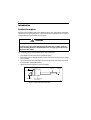
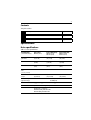
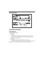
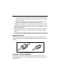
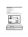
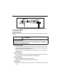
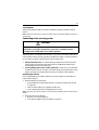
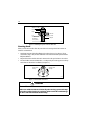
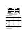
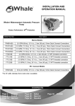
Linear Drive
Installation Guide
Drives covered:
M81130 Type 1 Linear Drive 12 V
M81131 Type 2 (short) Linear Drive 12 V
M81132 Type 2 (long) Linear Drive 12 V
M81133 Type 2 (short) Linear Drive 24 V
M81134 Type 2 (long) Linear Drive 24 V
Document number: 81175-5
February 2007
4
Important information
Safety notices
WARNING
Product installation
This equipment must be installed in accordance with the instructions
contained in this handbook. Failure to do so could result in poor product
performance, personal injury and/or damage to your boat.
Because correct performance of the boat’s steering is critical for safety,
we STRONGLY RECOMMEND that an Authorized Raymarine Service
Representative fits this product.
WARNING
Navigation aid
When this product is used within a navigation system, it is only an aid to
navigation. It’s accuracy can be affected by many factors, including equipment
failure or defects, environmental conditions and improper use or handling. It is
the user’s responsibility to exercise common prudence and navigational
judgements. This product should not be relied upon as a substitute for such
prudence and judgement. Always maintain a permanent watch so that you can
respond to situations as they develop.
EMC conformance
All Raymarine equipment and accessories are designed to the best industry standards for use
in the recreational marine environment. The design and manufacture of Raymarine
equipment and accessories conform to the appropriate Electromagnetic Compatibility (EMC)
standards, but correct installation is required to ensure that performance is not compromised.
Handbook information
To the best of our knowledge, the information in this handbook was correct when it went to
press. However, Raymarine cannot accept liability for any inaccuracies or omissions it may
contain. In addition, our policy of continuous product improvement may change
specifications without notice. As a result, Raymarine cannot accept liability for any
differences between the product and the handbook.
5
Waste Electrical and Electronic Equipment Directive
The Waste Electrical and Electronic Equipment (WEEE) Directive requires the
recycling of waste electrical and electronic equipment. Whilst WEEE does not
apply to some of Raymarine’s products, we support its policy and ask you tobe
aware of how to dispose of this product.
The crossed out wheelie bin symbol, illustrated above, and found on our products signifies
that this product should not be disposed of in general waste or landfill.
Please contact your local dealer, national distributor or Raymarine Technical Services for
information on product disposal.
Warranty
To register your new Raymarine product, please take a few minutes to fill out the warranty
card. It is important that you complete the owner information and return the card to receive
full warranty benefits. Alternatively you can register your product at;
www.raymarine.com
6
Introduction
Product description
Welcome to the installation guide for the Raymarine linear drive. This product is intended to
operate the boat’s steering mechanism as part of a Raymarine autopilot system. It is designed
for boats with existing mechanical steering systems.
CAUTION
Linear drive
This drive moves the rudder directly from the tiller arm or rudder quadrant.
Before installing the drive, check that the boat’s steering system can be backdriven from the rudder..
The outstanding design of the Raymarine linear drive unit provides:
• powerful thrust, fast hardover times and quiet operation
• low backdrive force, to minimize the drive’s effect on the boat’s steering when the autopilot is in standby
• a powerful electric motor controlled by an electromagnetic fail-safe clutch, using a high
tensile belt drive and epicyclic gearbox
• high performance for minimum current consumption
Clutch cable
Push rod
Rod end
Motor cables
Mounting foot
Motor, gearbox and
clutch assembly
Figure 1: Main parts of the linear drive
D5075-1
7
Contents
This guide contains:
1
Product specifications
page 7
2
Installation instructions
page 8
3
Maintenance information
page 17
Specifications
Drive specifications
Table 1-1: Drive specifications
Performance*
(at nominal voltage)
Type 1 (T1)
M81130 (12 V)
Type 2 short (T2S)
M81131 (12 V)
M81133 (24 V)
Type 2 long (T2L)
M81132 (12 V)
M81134 (24 V)
Maximum boat displacement
10,000 kg
(22,000 lb)
15,000 kg
(33,000 lb)
20,000 kg
(44,000 lb)
Peak thrust
295 kg
(650 lb)
480 kg
(1,050 lb)
480 kg
(1,050 lb)
Maximum stroke
300 mm
(12 in)
300 mm
(12 in)
400 mm
(16 in)
Hardover to hardover
time
(+/- 35º, no load)
11 sec
11 sec
14 sec
Maximum rudder
torque
735 Nm
(6,500 lb.in)
1,190 Nm
(10,500 lb.in)
1,660 Nm
(14,700 lb.in)
Power consumption
(typical average)
18-36 W
Other information
(applies to Types 1 and 2 short/long)
48-72 W (12 V)
66-96W (24 V)
protected for use in engine compartments
CE approvals - conforms to:
89/336/EC (EMC), EN60945:1997
94/25/EC (RCD), EN28846:1993
8
Drive dimensions
50 mm (2 in)
197 mm (7.8 in)
A (midstroke)
114 mm (4.5 in)
79 mm (3.1 in)
90º
4 fixing holes suitable
for 10 mm (0.4 in) bolts
Drive
Type 1
Type 2 (short)
Type 2 (long)
Dimension 'A'
700 mm (27.5 in)
700 mm (27.5 in)
850 mm (33.5 in)
D5081-1
Figure 2: Linear drive dimensions
Installation instructions
Parts required
To install this drive you will need:
• Parts supplied:
• linear drive
• mounting foot assembly, consisting of: foot, pivot pin, washer (x2), R-clip (x2)
• tiller pin assembly (see Figure 6 ) consisting of: tiller pin, R-clip, top washer, lock
washer, nut (1/2 inch UNC nylock)
• Additional parts:
• suitable securing bolts and lock nuts/lock washers (see page 13)
• suitable cable and electrical connectors for the drive motor and clutch (see page 15)
Note: Make sure you have obtained these additional parts before you start installation.
9
Installation steps
WARNING
Electrical safety
Make sure you have switched OFF the power supply before you start
installing this product.
Follow these steps to install your linear drive unit:
1
Consult the EMC installation guidelines.
page 9
2
Mount the drive.
page 11
3
Connect to the course computer.
page 15
4
Complete the post-installation check.
page 16
1. EMC installation guidelines
All Raymarine equipment and accessories are designed to the best industry standards for use
in the recreational marine environment.
Their design and manufacture conforms to the appropriate Electromagnetic Compatibility
(EMC) standards, but correct installation is required to ensure that performance is not
compromised. Although every effort has been taken to ensure that they will perform under all
conditions, it is important to understand what factors could affect the operation of the
product.
The guidelines given here describe the conditions for optimum EMC performance, but it is
recognized that it may not be possible to meet all of these conditions in all situations. To
ensure the best possible conditions for EMC performance within the constraints imposed by
any location, always ensure the maximum separation possible between different items of
electrical equipment.
For optimum EMC performance, it is recommended that wherever possible:
• Raymarine equipment and cables connected to it are:
10
• At least 3 ft (1 m) from any equipment transmitting or cables carrying radio signals
e.g. VHF radios, cables and antennas. In the case of SSB radios, the distance should be
increased to 7 ft (2 m).
• More than 7 ft (2 m) from the path of a radar beam. A radar beam can normally be
assumed to spread 20 degrees above and below the radiating element.
• The equipment is supplied from a separate battery from that used for engine start. Voltage drops below 10 V, and starter motor transients, can cause the equipment to reset. This
will not damage the equipment, but may cause the loss of some information and may
change the operating mode.
• Raymarine specified cables are used. Cutting and rejoining these cables can compromise
EMC performance and must be avoided unless doing so is detailed in the installation
manual.
• If a suppression ferrite is attached to a cable, this ferrite should not be removed. If the ferrite needs to be removed during installation it must be reassembled in the same position.
Suppression ferrites
The following illustration shows typical cable suppression ferrites used with Raymarine
equipment. Always use the ferrites supplied by Raymarine. This product has ferrites mounted
internally.
D3548-2
Figure 3: Typical suppression ferrites
Connections to other equipment
If your Raymarine equipment is to be connected to other equipment using a cable not
supplied by Raymarine, a suppression ferrite MUST always be attached to the cable near to
the Raymarine unit.
11
2. Mounting the drive
Mounting the drive unit involves four main steps:
•
•
•
•
ensuring correct drive alignment
securing the drive to the boat
connecting the drive to the steering system
completing a steering check
Drive alignment
When mounting the linear drive unit, check that it is aligned correctly:
• The main drive assembly must be at right angles to the mounting surface (see Figure 4 ).
• The drive unit must be at right angles to the tiller arm when the rudder is amidships (see
Figure 4 ).
Side view
A (mid stroke)
90º
Drive
Type 1
Type 2 short
Type 2 long
A (mid stroke)
700 mm (27.5 in)
700 mm (27.5 in)
850 mm (33.5 in)
B (tiller arm radius)
250 mm (10 in)
250 mm (10 in)
355 mm (14 in)
Top view
90º
B (tiller arm
radius)
D5077-1
Figure 4: Drive unit alignment
• The push rod must be accurately aligned with the tiller arm plane of rotation. The ball end
fitting only allows up to 5 degrees misalignment between the push rod and tiller arm
plane of rotation (see Figure 5 ).
CAUTION
Alignment
Accurate angular alignment is extremely important. You must not exceed this
+/- 5 degree limit under any circumstances.
12
5º Max.
5º Max.
D5078-1
Figure 5: Alignment between push rod and tiller arm plane of rotation
Securing the drive
Mounting location
Before you secure the drive to your boat, you must first check the suitability of the mounting
location.
CAUTION
Mounting location
Consult the boat manufacturer if you have any doubt about the strength or
suitability of the mounting location.
• Structural strength:
• This drive produces a considerable amount of force, so you must mount it on a solid
structure (i.e. a substantial frame member) in the boat. In some cases you may need to
build a special frame to mount the drive unit.
• To prevent excess noise and vibration, do not attach this drive to any structures that
support cabins.
• Drive orientation:
• You can attach the drive unit mounting foot to any suitable horizontal or vertical surface. If required, you can also mount the drive unit upside down.
• General position:
• Refer to the EMC installation guidelines (page 9)
• Make sure the drive will be accessible for future servicing.
• Environment:
• This drive is not waterproof, so you should mount it in a dry location, clear of any bilge
water.
13
Securing bolts
Attach the mounting foot with four stainless steel M10 (3/8 inch) bolts and lock nuts/lock
washers.
Note: Always mount the drive as securely as possible to make sure it performs reliably and remains cor-
rectly aligned.
Connecting to the steering system
CAUTION
Equipment strength
Consult the steering gear manufacturer if you have any doubt about the
strength of the existing tiller arm or rudder quadrant.
This drive produces a considerable amount of force, so you must ensure that your tiller arm or
rudder quadrant can cope with the peak thrust specified in the Table 1-1, Drive specifications.
Use one of these methods to attach the push rod to the rudder stock:
1. Independent tiller arm: we recommend that you attach the linear drive unit to the
rudder stock via an independent tiller arm (the Edson and Whitlock companies offer
standard fittings for their steering systems).
2. Steering linkage tiller arm or rudder quadrant: in certain cases, you may be able
to attach the push rod to the same tiller arm or rudder quadrant used by the main steering
linkage. Consult the steering manufacturer before you modify the rudder quadrant.
Attaching the rod end
Use the supplied tiller pin assembly to attach the rod end to the tiller arm, at the tiller arm
radius shown in Figure 4 .
1. Attach the tiller pin to the tiller arm:
• insert the tiller pin through the tiller arm hole, so the flange remains above the arm
(see Figure 6 )
• make sure that the tiller pin is a tight fit in the tiller arm
• use the supplied lock washer and fully tighten the lock nut
Note: If necessary, you will need to drill a 13 mm (0.52 in) hole in the tiller arm at the radius shown in
Figure 4 .
2. Attach the rod end to the tiller pin:
• place the rod end onto the tiller pin
• secure with the supplied washer and R-clip (see Figure 6 )
14
R-clip
Washer
Rod end
Flange
Tiller arm
Lock nut
Lock
washer
Tiller pin
Hole diameter
13 mm (0.52 in)
D5076-1
Figure 6: Attaching the push rod to the tiller arm
Steering check
When you have mounted the drive unit, turn the boat’s steering wheel from hardover to
hardover and check that:
• Angular movement of the ball end fitting is less than 5 degrees (see Figure 5 ). If you
exceed this 5 degree limit, the drive will catch on the tiller arm/rudder quadrant and the
ball joint will bind.
• No part of the drive unit fouls the boat’s structure when the push rod moves in and out.
• The total rudder movement is limited to +/- 35 degrees by the steering system end stops
rather than the linear drive’s end limits (see Figure 7 ).
Steering system
end stop
Steering system
end stop
35º
35º
D5079-1
Figure 7: Total rudder movement
CAUTION
Linear drive
Make sure rudder movement is limited by the steering system end stops
before the push rod reaches its end stop. Failure to do this could damage
the drive and will invalidate the warranty.
15
WARNING
Moving parts
Keep clear of moving steering systems at all times. Protect moving parts
from access during normal use.
3. Connecting to the course computer
WARNING
Electrical safety
Make sure the power supply is switched OFF before you make any
electrical connections.
The linear drive unit has electrical connections for:
• the drive motor: two single-core cables: red and black
• the clutch: a two-core cable with red (+) and blue (-) cores
Follow these steps to connect the linear drive to the course computer:
1. Measure the distance of cable run from the drive unit to the course computer:
• use Table 1-1 to identify the appropriate motor cable size
• use at least 1.5 mm2 (16 AWG) copper cable for the clutch
2. Join these cables to the drive cables using appropriate electrical connectors or junction
boxes at the correct power rating.
3. Route the cables back to the course computer, taking into account the EMC installation
guidelines (see page 9).
4. Connect the cables to the course computer (see Figure 8 ):
• CLUTCH cable: red core to +ve, blue core to -ve
• MOTOR cables: at this stage you can connect either motor cable to either terminal.
You will check these connections after installing the rest of the autopilot system.
16
OFF
SWITCH
– +
A B
POWER MOTOR
– –
– +
– +
lk CLUTCH
SOLENOID CLUTCH
Type 150/400 course computer
– +
1
2
POWER MOTOR
Type 100/300 course computer
D5080-1
Figure 8: Cable connections at course computer
Table 1-1: Recommended cable sizes
Cable length
(drive unit to course computer)
Cable gauge
(AWG)
Copper area
(mm2)
Type 1 drive
up to 3m (10ft)
up to 5m (16ft)
up to 7m (23ft)
up to 10m (32ft)
up to 16m (52ft)
14
12
10
8
6
2.5
4
6
10
16
Type 2 drive 12 V (short/
long)
up to 5m (16ft)
up to 7m (23ft)
up to 16m (52ft)
10
8
6
6
10
16
Type 2 drive 24 V (short/
long)
up to 3m (10ft)
up to 5m (16ft)
up to 10m (32ft)
up to 16m (52ft)
12
10
8
6
4
6
10
16
4. Post installation checklist
Check the following points after installing the drive:
1. Is the mounting foot secured to a substantial structure on the boat?
2. Is the drive unit correctly aligned, i.e:
• Is the mounting foot correctly oriented?
17
• Is the drive mounted at right angles to the tiller arm, in a mid-stroke position, when
the rudder is amidships?
• Is the push rod accurately aligned with the tiller arm plane of rotation (less than 5
degrees variation)?
3. Is the linear drive rod end:
• securely attached to the tiller arm or quadrant?
• attached at the recommended tiller arm radius for the boat?
4. Are the motor and clutch cables correctly routed and securely connected to the course
computer?
5. Have you completed a hand-steering check (see page 14)?
Note: When you have installed the entire autopilot system, you will need to complete an autopilot
steering check. Refer to the control unit handbook for more details.
Maintenance
Please make the following checks before each passage:
•
•
•
•
Ensure that all connections and mountings are secure.
Ensure that the drive is aligned correctly.
Ensure that cables have no signs of wear or damage.
Check for unusual noisy operation, such as clicking or grinding noises, or unusual vibration. If any of these are detected, the drive must be taken to a Raymarine authorized service representative before further use.
• Ensure that the drive is not wet or exposed to water.
• Ensure that the swivel joint and rose-end are lightly greased with waterproof grease.
Note: The drive should be serviced every 2 years or 1000 hours of use, whichever comes first, by a Ray-
marine authorized service representative.
EMC servicing and safety guidelines
• Raymarine equipment should be serviced only by authorized Raymarine service representitives. They will ensure that service procedures and replacement parts used will not affect
performance. There are no user serviceable parts in any Raymarine product.
• Some products generate high voltages, so never handle the cables/connectors when
power is being supplied to the equipment.
• When powered up, all electrical equipment produces electromagnetic fields. These can
cause adjacent pieces of electrical equipment to interact with one another, with a consequent adverse effect on operation. In order to minimize these effects and enable you to
get the best possible performance from your Raymarine equipment, guidelines are given
in the installation instructions, to enable you to ensure minimum interaction between different items of equipment, i.e. ensure optimum Electromagnetic Compatibility (EMC).
18
• Always report any EMC-related problem to your nearest Raymarine dealer. We use such
information to improve our quality standards.
• In some installations, it may not be possible to prevent the equipment from being affected
by external influences. In general this will not damage the equipment but it can lead to
spurious resetting action, or momentarily may result in faulty operation.
Product support
Raymarine products are supported by a worldwide network of distributors and Authorized
Service Representatives.
If you encounter any difficulties with this product, please contact either your national
distributor, or your service representative, or the Raymarine Technical Services Call
Center. Refer to the back cover or the Worldwide Distributor List for contact details.
Raymarine Inc
Raymarine Ltd
21 Manchester Street
Anchorage Park
Merrimack
Portsmouth, Hampshire
NH 03054-4801, USA
England PO3 5TD
Telephone +1 603 881 5200
Telephone +44 (0)23 9269 3611
Fax +1 603 864 4756
Fax +44 (0)23 9269 4642
www.raymarine.com
www.raymarine.com
Raymarine Technical Services Call Center
UK: +44 (0)23 9271 4713 or
USA: +1 603 881 5200
+44 (0)23 9269 3611 ext. 1083