1
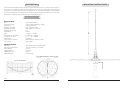
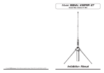
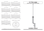
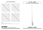
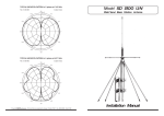
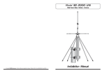
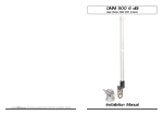
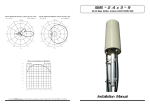
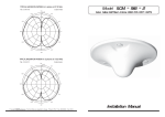
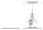
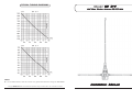
TYPICAL TUNING DIAGRAMS
Model GP 3-F
VHF Base Station Antenna 135-175 MHz
NOTE:
• It is recommended to use the curves as a guide and fine-tune using an SWR-Meter.
B Copyright SIRIO antenne - Technical Data are subjected to change - Printed in ITALY - Rev. 01/07/1998- Cod. ID238
Installation Manual
DESCRIPTION
5/8 λ Ground Plane base station antenna for land and marine service. It works on the frequency
range of 135-175 MHz by using the cutting diagram enclosed. The matching coil is DC feeded
for a perfect protection from the static discharges. GP 3-F is made of fiber-glass and assembled
on a very strong base of chromed die-cast metal to get the maximum robustness and the best
performance. Tuning is easy by following the attached directions.
SPECIFICATIONS
Electrical Data
Type
Frequency Range
Impedance
Radiation (H-plane)
Radiation (E-plane)
Radiation angle deg.
Polarization
Gain
Bandwidth at V.S.W.R. 2:1
V.S.W.R. at res. freq.
Max Power
Feed System / Position
Connection
:
:
:
:
:
:
:
:
:
:
:
:
:
5/8 λ Ground Plane
135-175 MHz tunable by cutting
50 Ω Unbalanced
360o Omnidirectional
Beamwidth at -3 dB = 69o
25o
Vertical
1.5 dBd - 3.65 dBi
4.8 MHz at 135 MHz
≤ 1.2 : 1 at 135 MHz
200 Watts
Transformer DC-Ground / Base
UHF Female
Mechanical Data
Materials
Wind Load / Resistance
Wind Surface
Height (approx.)
Weight (approx.)
Mounting Mast
:
:
:
:
:
:
Glass Fibre, Nylon, Chromed Brass
23 N at 150 Km/h / 150 Km/h
0.02 m2
1335 mm
585 gr
∅ 25-30 mm
ID238
MOUNTING INSTRUCTIONS