1
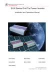
Installation and Safety Manual
for the
c-Si M60 NA 30119 Family of
Crystalline Photovoltaic Modules
Copyright Bosch Solar Energy Corp., version 1.0
Page 1 of 19
Table of Contents
1.
INTRODUCTION .............................................................................................................................. 4
A.
2.
Disclaimer of Liability ................................................................................................................... 4
SAFETY INFORMATION ................................................................................................................ 4
A.
General Considerations ............................................................................................................... 4
B.
Installation Precautions ................................................................................................................ 5
C.
Electrical and Optical Safety ........................................................................................................ 6
D.
Fire Safety .................................................................................................................................... 6
3.
MODULE PERFORMANCE AND SAFETY STANDARDS .............................................................. 7
A.
Standard Test Conditions ............................................................................................................. 7
B.
Underwriters Laboratories Information ........................................................................................ 7
C.
National Electrical Code (NEC) ................................................................................................... 7
4.
LOCATION OF SOLAR MODULES ................................................................................................. 7
A.
5.
Orientation, Tilt Angle, Shading, & Performance ........................................................................ 7
BOSCH SOLAR ENERGY MODULE CHARACTERISTICS ........................................................... 8
A.
Electrical Characteristics .............................................................................................................. 8
B.
Thermal Characteristics ............................................................................................................... 8
C.
Bypass diodes .............................................................................................................................. 9
D.
Mechanical Specifications ............................................................................................................ 9
6.
MECHNICAL INSTALLATION ....................................................................................................... 10
A.
Module Orientation and Handling Safety ................................................................................... 10
B.
Wind and Snow Loads ............................................................................................................... 11
C.
Mounting Methods ...................................................................................................................... 11
D.
Bolting Mounting Method Example ............................................................................................ 11
7.
ELECTRICAL INTERCONNECTIONS .......................................................................................... 12
A.
Module To Module Interconnection .......................................................................................... 12
B.
Grounding................................................................................................................................... 14
Copyright Bosch Solar Energy Corp., version 1.0
Page 2 of 19
8.
STORING, TRANSPORTING AND UNPACKING SOLAR MODULES ......................................... 16
A.
Packaging................................................................................................................................... 16
B.
Unpacking Instructions ............................................................................................................... 17
C.
Safety Considerations ................................................................................................................ 17
9.
PRODUCT SUPPORT ................................................................................................................... 18
10.
CARE AND MAINTENANCE ..................................................................................................... 18
A.
Module Cleaning ........................................................................................................................ 18
B.
Inspection and Repair ................................................................................................................ 18
11.
END OF LIFE ............................................................................................................................. 19
Copyright Bosch Solar Energy Corp., version 1.0
Page 3 of 19
1. INTRODUCTION
Thank you for purchasing this Bosch Solar Energy product. In 2011, the Bosch Group proudly
celebrated its 125 year anniversary, symbolizing the company’s long-term viability and
continued commitment to bringing “Invented for Life” solutions to market. Bosch Solar Energy
is the photovoltaic business operation within the Bosch Group and manufactures high-quality
solar modules. Our solar modules utilize advanced technology components to supply
environmentally friendly solar energy for many years when correctly installed and operated.
This document provides recommendations for the installation and maintenance of B os ch S olar
E ne r gy’s cr ys tall ine s ili c on photovoltaic (PV) modules and also identifies the hazards
associated with the handling and installation of these products.
Before installing, wiring and using a B o s c h S o l a r E n e r g y module, it is important to
thoroughly read this manual and understand the instructions. Installers must understand the
basic principles of electricity and electrical apparatuses as well as article 690 of the National
Electrical Code. Please pay special attention to any safety instructions designated with
the following caution symbol:
CAUTION:
A. Disclaimer of Liability
Since the use of this Installation and Safety Manual and the conditions or methods of installation,
operation, use and maintenance of the module are beyond the control of Bosch Solar Energy,
Bosch Solar Energy does not assume responsibility and expressively disclaims liability for loss,
damage injury or expense arising out of or in any w a y connected with such installation
operation, use or maintenance of the module.
Bosch Solar E n e r g y assumes no responsibility for infringement of patents or other rights of
third parties which may result from use of the module. No license is granted by implication
or otherwise under any patent or patent rights. The information in this Manual is based on
Bosch Solar Energy‘s knowledge and experience and is believed to be reliable; but such
information including product specifications (without limitations) and suggestions do not
constitute a warranty, expressed or implied. Bosch Solar Energy reserves the right to make
changes to the product, specification or this Manual without prior notice.
2. SAFETY INFORMATION
A. General Considerations
Bosch Solar E n e r g y modules should only be installed by qualified installers with adequate
solar PV installation experience.
Take note of all relevant laws, regulations, guidelines and safety measures when handling solar
photovoltaic modules.
Prevent accidents such as electric shocks during the installation, operation, maintenance and
disposal of solar modules by taking the appropriate precautions.
Keep unauthorized persons and animals away from solar energy systems. Pay particular attention
to children.
Copyright Bosch Solar Energy Corp., version 1.0
Page 4 of 19
Take special note of occupational safety and accident prevention regulations applicable to the work
in question.
Bosch Solar modules can be combined with other components to form a photovoltaic system. In
this case you must also follow the installation and operation instructions issued for these additional
components.
You must comply with the standards and regulations applicable to PV installations, such as
t h e National Electrical Code (NEC) and local safety and building codes, the grid operator’s
technical connection requirements, and trade association rules concerning accident prevention.
Failure to comply can lead to significant personal injury and equipment damage.
B. Installation Precautions
Use appropriate protective safety equipment as recommended by local safety codes and
practices (e.g., hard hat, scaffolding, steel toe shoes, gloves and restraining harness) and
exercise caution particularly when installing modules at height (e.g. on a roof). Solar modules
are heavy and should always be handled by two people.
CAUTION: Always adhere to the following installation precautions:
•
ALWAYS handle solar modules by their long sides and keep sharp objects away from the
module surface when handling.
•
DO NOT place heavy loads or drop objects on the module
•
DO NOT install a solar module in which the backsheet has been damaged
•
DO NOT walk on, bend or drop the solar module
•
DO NOT attempt any installation in adverse weather conditions (high winds, rain or when ice
or snow is present)
•
NEVER leave a module unsupported or unsecured. If a module falls, the glass could break.
A module with broken glass cannot be repaired and must not be used.
•
NEVER attempt to modify a solar module or take it apart. Never remove any markings or
labels applied or parts fitted by the manufacturer. Do not apply any paint or adhesive to a
solar module
•
DO NOT attempt to install or service any portion of the PV system unless you understand
the electrical operation and are fully qualified to do so.
•
DO NOT drill holes in the frame or glass of the module. Doing so will void the warranty.
•
Have a fire extinguisher, and first aid kit when performing field work on all energized
equipment where the system open circuit voltage is 30 volts or greater.
•
Since sparks may be produced, do not install module where flammable gases or vapors are
present
•
DO NOT work on modules when they are wet. If a wet module is cracked or broken the full
system voltage may be present.
•
ALWAYS mount the solar module so that the junction box is at the upper edge of the module
•
Ensure that all electrical connections are properly connected and protect them from
interference from unauthorized personnel or animals
Copyright Bosch Solar Energy Corp., version 1.0
Page 5 of 19
C. Electrical and Optical Safety
Photovoltaic (PV) modules generate electricity whenever they are exposed to light. Lethal voltages
and/or a shock hazard may be present in photovoltaic modules and arrays even during sunlight hours
and even at low light levels. This hazard increases when multiple modules are connected together to
provide higher system voltage or current levels. Dangerous voltages may also be present at night
from connections to batteries and feedback from inverters or other system components.
Cover the front surface of the modules with an opaque material to prevent the modules from
generating electricity. Ensure that both the front and back surfaces of the module and the sheaths of
the connecting cables are undamaged.
Improper electrical connections can result in electrical arcing which can ignite any flammable material
located in close proximity. When flammable material is within 30 cm (12 in.) of either the solar
module or any of the electrical connections then install an appropriate flame barrier to prevent
potential risks of fire.
CAUTION: Always adhere to the following installation precautions:
•
DO NOT damage, pull, bend or place heavy loads on the cables
•
DO NOT connect the cables if the terminals are wet
•
DO NOT disconnect module cables under electrical load
•
DO NOT attempt to open the diode housing or junction box located on the back side of any
Bosch Solar Energy module. There are no user serviceable parts inside. Opening the
junction box may expose the individual to an electrical shock hazard and will void the
warranty.
•
Remove any jewellery or other metallic ad ornme nts to av oid accidental electr ical
contact and use insulated tools
•
A t w o-person team is to be used while performing field work on all energized equipment
where the system open circuit voltage is 30 volts or greater.
•
Wear electrical insulating gloves rated at 1000 volts and suitable eye protection
when working on systems where the system open circuit voltage is 30 volts or greater.
•
DO NOT touch terminals while the module is exposed to light without wearing electrical
insulating gloves.
•
DO NOT connect or disconnect a module unless the array string is open- circuited or
all of the modules in the string are covered.
•
Prevent sunlight from being concentrated or reflected artificially onto a solar module. In
particular, do not use any concentrating lenses or mirrors.
D. Fire Safety
The Bosch Solar Energy c-Si M60 NA 30119 modules have been certified by Underwriters
Laboratories to comply with UL1703 Class C fire rating. To satisfy the conditions of this rating when
installing on a building, you must mount the modules using standoff or rack methods over a fire
resistant roof covering rated for the application. The module listing may not apply if the modules are
mounted integral to the roof or wall of a building, and does not cover marine or vehicle applications.
Refer to your local authority for guidelines and requirements of building or structural fire safety.
Copyright Bosch Solar Energy Corp., version 1.0
Page 6 of 19
3. MODULE PERFORMANCE AND SAFETY STANDARDS
A. Standard Test Conditions
The module electrical r a t i n g s a t Standard Test Conditions appear on the label on the back of
2
each module. Standard Test Conditions are defined as an irradiance le v e l of 1000W/m , AM 1.5
spectrum and a cell temperature of 25°C (77°F). It is important to note that, under normal
o p e r a t i n g conditions, a photovoltaic module is likely to experience conditions that produce
more current and/or voltage than reported at Standard Test Conditions.
B. Underwriters Laboratories Information
These Bosch Solar Energy modules are listed to UL 1703, the Standard for Safety for Flat-Plate
Photovoltaic Modules and Panels. This Standard covers solar PV modules intended for
installation on or integral with buildings or to be freestanding (not attached to buildings), in
accordance with the National Electrical Code (NFPA 70), appropriate building codes, and any
other applicable local codes in the US.
C. National Electrical Code (NEC)
The National Electrical Code (NEC) covers the installation of photovoltaic systems and must be
adhered to when systems are designed and installed. Article 690, Solar Photovoltaic Systems, of
the NEC applies to solar photovoltaic energy systems including the array circuit(s), power
conditioning unit(s) and controller(s) for such systems.
Under normal conditions, a photovoltaic module is likely to experience conditions that produce
more current and/or voltage than reported at Standard Test Conditions. As previously
mentioned, the values of Isc and Voc marked on the modules must be sized according to section
690-8 of the National Electrical Code. All wiring shall be in accordance with the NEC, and
grounding method of the module arrays shall comply with the NEC, Article 250.
4. LOCATION OF SOLAR MODULES
A. Orientation, Tilt Angle, Shading, & Performance
Photovoltaic modules generate maximum power when facing directly towards the sun. PV
systems can track the sun or remain in a fixed tilt position. Tracking systems will produce more
energy o n a n a n n u a l b a s i s but are more costly and m a y require more maintenance.
Most PV systems are designed with a fixed tilt. The further North from the equator, the greater
the tilt angle required. Since applications vary widely, be sure to consult a PV system integrator
or use a commercially available software program to determine the expected system energy
output. The following chart may serve as a rule of thumb.
Site Latitude
0-10
11-20
21-30
31-40
41+
Copyright Bosch Solar Energy Corp., version 1.0
Horizontal Tilt Angle
= 10 Degrees
= Latitude
= Latitude + 5~
= Latitude + 10~
= Latitude + 15~
Page 7 of 19
In order to minimize module soiling, it is not recommended to set the tilt angle below 10 degrees.
Dirt tends to accumulate on modules installed at lower angles and does not wash off as readily
during rainfall. Dirt accumulation, debris and even snowfall on the module will reduce its
energy output.
Select a location with the best possible solar radiation for the photovoltaic system you want to
install. Your choice of location should take into account the seasonal changes in light conditions.
Modules should be located in areas with an unobstructed view of the sun where they will receive
maximum exposure of sunlight for the longest possible time during the day. Shadowing caused
by buildings, roof pipes and vents, trees, utility poles and other obstructions may significantly
reduce the module energy output.
In systems that are configured with multiple rows of modules, the rows must be spaced far
enough apart to minimize the impact of shading on other rows. This distance is dependent on
the latitude and tilt angle at which the system is installed. The closer to the equator, requires a
lower tilt angle and therefore the shorter this distance. The further from the equator, higher tilt
angle and therefore the greater this distance needs to be. If there are questions regarding the
optimum configuration in which to arrange, mount or wire the modules, obtain assistance from
your Bosch Solar Energy dealer or distributor or retain the services of an engineer familiar
with the proper design of PV systems.
5. BOSCH SOLAR ENERGY MODULE CHARACTERISTICS
A. Electrical Characteristics
The following electrical characteristics were measured under Standard Test Condition (STC):
Electrical Characteristic
Model Designator (Part No. Suffix)
Maximum Power (Pmax)
Open Circuit Voltage (Voc)
Short Circuit Voltage (Isc)
Maximum Power Voltage (Vmpp)
Maximum Power Current (Impp)
Maximum System Voltage
Maximum reverse current protection
Measure
-Watts
Volts
Amps
Volts
Amps
Volts
Amps
c-Si M60 NA 30119
240Wp
245Wp 250Wp 255Wp
240
245
250
255
37.07
37.27
37.47
37.67
8.51
8.61
8.71
8.81
30.16
30.36
30.56
30.79
7.98
8.08
8.18
8.28
600
17
Please note the following: the electrical characteristics are within ±10 percent of the indicated values
2
of Isc, Voc, and Pmax under Standard Test Conditions (i.e. irradiance of 1000W / m , AM 1.5
spectrum, and a cell temperature of 25°C (77°F)).
B. Thermal Characteristics
Thermal Characteristic
Model Designator (Part No. Suffix)
Operating Temperature Range
Temp. Coefficient of Maximum Power
Temp. Coefficient of Open Circuit Voltage
Temp. Coefficient of Short Circuit Voltage
Copyright Bosch Solar Energy Corp., version 1.0
Measure
-°C
% / °C
% / °C
% / °C
240Wp
c-Si M60 NA 30119
245Wp
250Wp
-40 to 85
-0.429
-0.321
+0.067
255Wp
Page 8 of 19
C. Bypass diodes
All modules are equipped with factory installed bypass diodes in the junction box (see table below).
The use of bypass diodes reduces the risk of heating of the shaded cells, limiting the current that can
pass through them and thereby avoiding damage to the cells.
Maximum Reverse
Voltage
45V
Average Rectified
Forward Current
15A
No. Diodes per
Module
3
Total No. of Cells
per Diode
20
CAUTION: DO NOT attempt to open the diode housing or junction box located on the back
side of the module. There are no user serviceable parts inside. Opening the junction box may
expose the individual to an electrical shock hazard and will void the warranty.
D. Mechanical Specifications
The Bosch Solar Energy module dimensions are summarized in the table below.
Mechanical Characteristic
Model Designator (Part No. Suffix)
Dimensions in inches (L x W x H)
Dimensions in mm (L x W x H)
Weight in pounds
Weight in kilograms
240Wp
c-Si M60 NA 30119
245Wp
250Wp
255Wp
64.96 x 38.98 x 1.65
1,650.0 x 990.0 x 42.0
41.89 +/- 2.2
19.0 +/- 1
Figures 5A, 5B and 5C provide illustrations of the module mounting holes, frame design and general
dimensions follow below. Please note that all units are in millimeters.
Figure 5A: Module Mounting Hole Locations
Copyright Bosch Solar Energy Corp., version 1.0
Figure 5B: Frame Side View
Page 9 of 19
Figure 5C: Module dimensions
6. MECHNICAL INSTALLATION
A photovoltaic system must be installed so that it can withstand environmental influences such as
wind, rain, hail, and snow. If solar modules are to be installed on a roof or façade, a suitable mounting
system will be required to enable the solar modules to be properly fastened. Make sure that the
mounting system structure and all components used for fastening the solar modules in place comply
with all relevant local building codes and regulations.
CAUTION:
The information in this section only suggests possible methods of securing the PV modules to a
‘module mounting system.’ It is the sole responsibility of the user and/or installer to verify that the
module mounting system and mounting method are properly engineered and in accordance with local
building codes and regulations.
A. Module Orientation and Handling Safety
Bosch Solar Energy PV modules can be arranged in either landscape or portrait position on flat or
sloped roofs or surfaces and at flat or tilted angles. Always use caution when mounting a module
on tilted angles or sloped roofs so the module does not slide out of position while attaching it to
the module mounting system. It is also recommended that modules are mounted so that the
junction box shall be in the uppermost position to minimize the ingress of water. A clearance of
6mm / 0.25” between modules is sufficient in most installations to accommodate thermal
expansion. However, the appropriate clearance is dependent upon installation specific factors
including the module mounting system, ambient temperature at the site and the maximum
Copyright Bosch Solar Energy Corp., version 1.0
Page 10 of 19
operating temperature of the module. Also it is important to note that the maximum distance
between modules should not exceed 12” based on using standard wiring. The minimum
recommended standoff distance between Bosch Solar Energy modules and the roof is 1.57 inches
(40mm).
B. Wind and Snow Loads
All s o l a r installations should also be in accordance with local building codes and regulations.
For proper structural design, it is recommended to retain the services of a structural engineer
experienced with the installations of PV systems. It is important to reference the most current
revision of ASCE 7 for determining the proper wind and snow load calculations for the project site.
Bosch Solar Energy modules have been evaluated by UL for a maximum positive or negative design
2
loading of 50 lbs/ft (2,400 Pa).
C. Mounting Methods
Bosch Solar Energy modules may be secured via a variety of traditional mounting methods including
bolt and clamp styles. Contact Bosch Solar Energy if alternate methods of mounting are required.
Regardless of mounting method employed, always thoroughly review and follow the instructions of the
mounting structure manufacturer. To comply with the requirements of UL 1703 the modules must be
fixed using hex-head bolts. For greater longevity, Bosch Solar Energy recommends that all fixings are
made of 316 grade (A4) stainless steel (not supplied). Prevention of the corrosive effects of dissimilar
metals must be considered when mounting the solar module frame (Aluminum) against other
materials.
D. Bolting Mounting Method Example
Many installations utilize the traditional ‘bolting’ mounting method (i.e. fastening the module to the
support structure via four (or sometimes six) mounting holes that are located on the mounting frame).
The recommended installation method is as follows:
1) Secure the module to the structure using the factory mounting holes or along the module
frame above the factory mounting holes (refer to Figure 6A)
2) A quantity of four ¼” (M6) stainless steel bolts with length less than ¾” (20 mm), with four ¼”
(M6) stainless steel nuts, washers, and spring washers are recommended for mounting one
module. (Figure. 6B).
3) The maximum mounting torque for the ¼” bolts should not exceed 12-15 ft-lbs or 9-10 N.m for
a M6 bolt
4) Please refer to Figures 5A and 5C for the module dimensions and hole locations
5) Maintain a gap of least ¼” (6 mm) between neighboring modules.
6) When mounting multiple rows of PV modules be sure to maintain enough distance to prevent
shading by adjacent rows.
7) Make sure to face the glass side of the module to the sun
8) DO NOT remove or alter the module frame. Creating additional mounting holes may damage
the module and reduce the strength of the frame and will invalidate the warranty.
Copyright Bosch Solar Energy Corp., version 1.0
Page 11 of 19
Figure 6A: Example Mounting Method
Figure 6B: Illustration of Mounting Hardware
The ‘clamp’ mounting style (i.e. using end clamps and mid clamps along the module frame for
securing modules to the racking system) may also be utilized. It is recommended that the clamp be
placed within +/- 1” (25 mm) of the centerline of the factory mounting hole.
CAUTION:
Contact Bosch Solar Energy if only the short frame edges are to be used for anchoring the module.
This type of mounting method typically requires additional analysis by Bosch Solar Energy. Failure to
do so may invalidate the warranty.
7. ELECTRICAL INTERCONNECTIONS
A. Module To Module Interconnection
Bosch Solar Energy modules have been designed to be easily interconnected. Each module
comes with one positive (+) cable with a plug on one end and one negative (-) cable with a
receptacle on one end. Both wires are connected inside of the junction box (diode housing).
Copyright Bosch Solar Energy Corp., version 1.0
Page 12 of 19
See Figure 7A below for more information. Modules are interconnected by inserting the
plug from one module into the receptacle of the next module in the array string. Secure the mated
connector pair to the inside flange of the module frame to protect it from damage. For added
safety, Bosch Solar Energy modules feature locking connectors that require a tool for
disconnection.
Figure 7A: Overview of Module Junction Box and Cables
Wiring Considerations
Always use cables and connection techniques consistent with the anticipated environmental
conditions and applicable codes related to the installation. For wiring that is exposed to
weather, select conductor cable that is sunlight (UV) resistance and that offers a minimum
rating of 90 °C (194 °F). Bosch recommends that all wiring be double insulated, use flexible
2
copper (Cu) conductors at least 3mm in diameter (AWG 12) and rated as USE-2 or equivalent.
The module cables should also be attached and supported to ensure adequate strain relief. If
cables are installed within a building then they should be installed in metallic cable conduits.
CAUTION
When selecting the minimum current carrying capacity of the cable please refer to the typical
short circuit current (Isc) rating* and multiply this by 1.56 times the number of solar modules
connected in parallel. Note that further safety factors may be required depending upon the
ambient temperature of the installation and the means of installation of the cables (e.g. conduit
installation). Refer to the local standards to ensure full compliance with legislation.
CAUTION
Under normal conditions, a photovoltaic module is likely to experience conditions that produce
more current and/or voltage than reported at Standard Test Conditions. Accordingly, the values
of Isc and Voc marked on this module* should be multiplied by a factor of 1.25 when
determining component voltage ratings, conductor ampacities, fuse sizes, and size of controls
connected to the PV output. Refer to Section 690-8 of the National Electrical Code for an
additional multiplying factor of 125 percent (80 percent derating) which may be applicable.
*Please note the following: the Isc and Voc ratings are printed on the product data sheet as
well as the label adhered to the rear side of the solar module
Copyright Bosch Solar Energy Corp., version 1.0
Page 13 of 19
Series and Parallel Wiring
The modules may be wired in series to produce the desired voltage output in the range of
maximum system voltage and input voltage of the required inverter. Connect the modules in
series electrically by connecting the positive (+) connector of one module to the negative (-)
connector of another. Only use modules of the same type for series connections. An arrangement
of several solar modules which are connected in series is often referred to as a “module string”.
To determine the maximum number of modules that may be connected in series, divide the
maximum system voltage as stated on the module label (or the maximum allowed by local
standards or codes, whichever is less) by the module open circuit voltage (Voc) printed on the
label, after correcting for temperature as required by local codes or standards.
The number of module strings connected in parallel without protective fuses should be limited to
two. If more than two strings are to be connected in parallel, then a series fuse is required for each
string in each non-earthed pole. Only DC fuses rated at the maximum system voltage should be
used. Maximum fuse rating should not exceed the maximum system voltage rating stated on the
module label.
DC Fuse Ratings
To calculate the minimum fuse size, multiply the short circuit current (Isc) rating of the module
by a factor of 1.56. The Isc value must take into consideration the maximum irradiation and
temperature of the installation site. If the loss of a fuse connection occurs, verify that the
maximum current rating was considered when calculating the fuse rating.
CAUTION
DO NOT connect or disconnect a Bosch Solar Energy module unless the array string is opencircuited or all of the modules in the a r r a y string are covered. Take appropriate steps to black out
the top (cell side) of the solar modules as much as possible. The connectors are not designed to
make or break the full system current. Do not direct concentrated artificial lighting sources on the
modules or panels.
B. Grounding
In order to ensure a code compliant installation, requirements for earth grounding and lightning
protection must be followed. In the United States, the grounding methods must comply with
Articles 250 and 690 of the National Electric Code (NEC).
According to the NEC, the installer must ground the m o d u l e frame. Use only UL Listed
grounding lugs suitable for outdoor. Alternate means of module grounding not covered within this
Manual may be acceptable. Contact Bosch Solar Energy for additional information regarding the
use of additional grounding techniques.
Please refer to Figure 7B for a typical earth grounding method for the module utilizing ground
lugs.
Copyright Bosch Solar Energy Corp., version 1.0
Page 14 of 19
Figure 7B: Installation of the grounding lug
In this grounding method the s e r r a t e d ‘ star’ washers are required for making a reliable
g r o u n d connection t h r o u g h t h e a n o d i z e d c o a t i n g a n d into the aluminum frame as
well as to prevent loosening of the screw over time.
An alternative method of attaching the grounding lugs may require the use o f #8-32 (4mm)
bolts, nut, star washers and lock washers. The ground lug shall be installed from the
bottom side of the frame using the paint cutting star washers, lock washer and bolt.
Torque t h e hex bolt (if used) to 50-70 in-lbs. This ground hardware can accommodate a
14AWG through 4AWG bare (stranded or solid) wire.
Copyright Bosch Solar Energy Corp., version 1.0
Page 15 of 19
8. STORING, TRANSPORTING AND UNPACKING SOLAR MODULES
A. Packaging
Bosch Solar Energy modules are shipped in pallet box assemblies that are specially designed to
provide the proper protection during shipment. The pallet box consists of the following components:
1) Wooden pallet
2) Plastic module corner protectors
3) Cardboard base, sleeve and cap
It is important to note that the pallets and plastic module corner protectors are the main components of
the packaging assembly that bare the vertical load.
Pallet Box Specifications
Quantity
23 modules
Dimensions (L x W x H)
1,728 x 1,148 x 1205 mm
68.03 x 45.20 x 47.44 in.
Weight
470 kg
1,026 lbs
Stack Limitation
Maximum 2 boxes
The pallet box dimensions are shown in Figure 8A below.
1,205mm
Figure 8A: Pallet Box Dimensions
Whenever the Bosch Solar Energy modules are stored or transported, care must be exercised to
ensure that they are stood upright in the packing units and that there is sufficient area to support each
solar module. Each module must also be secured against tipping over. When solar modules are
transported, they must always be in an upright position. Transporting the modules in a horizontal
position is not allowed.
Copyright Bosch Solar Energy Corp., version 1.0
Page 16 of 19
B. Unpacking Instructions
Bosch Solar Energy modules are shipped in a pallet box assembly as shown in Figure 8B. To unpack
the assembly, please use the following procedure:
1) Cut the polyethylene straps with cutting tools.
2) Remove the upper cap.
3) Lift up and remove the sleeve.
4) Remove the plastic bag with a cutting tool.
5) Remove the modules one at a time
Figure 8B: Pallet Box Assembly
C. Safety Considerations
Bosch recommends that the solar modules be stored indoors in their original packaging until ready for
final installation. Dry storage conditions are important for protecting the integrity of the cardboard
assembly components. Loose solar modules should be stored standing upright on wedge-shaped
corner protectors with suitable padding. Adequate padding must be placed between the individual
solar modules as well. The solar modules should be secured against tipping over.
CAUTION: Always adhere to the following pallet box handling precautions:
1) The module contains glass and is fragile. Handle the transportation box as well as the PV
module with care.
2) Wear gloves to avoid injury by sharp edges
3) DO NOT stack more than 2 pallet boxes on top of one another
4) DO NOT get pallet or cardboard components wet as they may collapse
after long-term exposure to moisture
5) Always maintain the pallet box in flat position.
ground may cause module breakage.
Stacking on uneven
6) Move 2 boxes at a time when transporting by fork lift
7) DO NOT cut the polyethylene straps until installation commences
Copyright Bosch Solar Energy Corp., version 1.0
Page 17 of 19
9. PRODUCT SUPPORT
Bosch Solar Energy is committed to offering high-quality products which are safe and reflect the state
of the art in technology – today and in the future. We value feedback and ideas from our installers and
users to help make our solar products better. For information or for service and technical support on
Bosch Solar Energy products, please contact Bosch Solar Energy via one of the methods listed below:
E-mail: [email protected]
Telephone: +1 650 356 3100
Website: www.bosch-solarenergy.com
10. CARE AND MAINTENANCE
Bosch Solar Energy modules require minimal care and maintenance in order to provide high
performance. Bosch Solar Energy recommends that system maintenance is carried out by qualified
personnel on a regular basis. This maintenance may include such tasks as verification of the integrity
of the electrical and mechanical connections, checking that any system alarms are operating correctly
and cleaning of the solar modules as required.
A. Module Cleaning
Solar modules may become soiled to varying degrees depending upon surrounding conditions and this
may reduce their performance. Periodic cleaning of the modules will ensure maximum output.
However, if modules are installed at height (e.g. on a roof) then cleaning should only be performed by
qualified personnel
•
•
•
•
•
CAUTION: When cleaning solar modules please take the following precautions:
Clean the module surface with a soft cloth or sponge using clean and neutral water base (nonammonia). To remove stubborn dirt you can use a mild, non-abrasive cleaning agent or
alcohol.
Only clean modules in the early morning or in the late afternoon when there is low solar
radiation and cells are producing less energy
DO NOT use either high-pressurized water, a steam cleaner or any kind of aggressive tool or
material that could scratch the surface of the modules.
DO NOT clean the modules with hot water when the ambient temperature is low or with cold
water when the modules are hot.
DO NOT attempt to remove snow or ice from the modules by means of scraping. Use a soft
brush to avoid creating micro-scratches in the module glass.
B. Inspection and Repair
When carrying out an inspection, please check that the electrical and mechanical connections are
clean, secure and undamaged. Be sure to take precautions against electric shock in the event of any
defects. Any faults must be rectified promptly.
Should any repairs become necessary to a Bosch Solar Energy module, it is essential that you contact
Bosch Solar Energy. Never under any circumstances attempt to repair the solar module yourself!
Bosch Solar Energy modules must only be serviced by specialist firms authorized by Bosch; otherwise
the product and performance warranties may be voided.
Copyright Bosch Solar Energy Corp., version 1.0
Page 18 of 19
11. END OF LIFE
When solar modules reach the end of their service life, they must be disposed of in accordance with all
relevant local, state, and national laws and regulations. They must never be disposed of as household
waste. It is the responsibility of the user to ensure that this product is disposed of properly. Please
contact your local waste disposal center or Bosch Solar Energy if you have any questions concerning
the proper disposal of this product.
Copyright Bosch Solar Energy Corp., version 1.0
Page 19 of 19