1
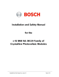
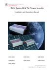
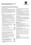
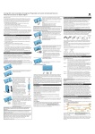
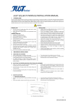
Solar module user manual
Conergy PM 225P-250P
1 Introduction
1.1 Short description
Conergy PM modules are solar modules for installation in photovoltaic systems.
1.2 About this manual
1.2.1 Subject of this manual
The subject of this manual is the installation and electrical connection of the Conergy PM module in a photovoltaic system.
This manual applies to the following modules: Conergy PM 225P-250P.
1.2.2 User group
The manual is intended to be used by the system owner and by qualified persons possessing technical skills and basic
electrical, electronic and mechanical knowledge related to photovoltaic systems. Please retain this manual for future
reference.
1.2.3 Symbols
Start of a step-by-step procedure with description of the goal of the procedure. Individually numbered steps
follow, which may be interrupted by background information, illustrations, or warnings.
Background and additional information or the status of a procedure. Appears between the steps of a
procedure, within the sequence/ course of a procedure.
Denotes a hazardous situation. Disregard of this instruction may lead to slight or moderate injury.
Denotes an extraordinarily hazardous situation. Disregard of this instruction may lead to serious, irreversible
injury or death.
1.3 Standards and technical directives
Conergy PM modules comply with the following standard:
| UL 1703
1.4 Intended use
Conergy PM modules are designed for use in photovoltaic systems. Any other use is deemed to be not as intended.
Intended use also includes compliance with the specifications stated in this installation manual. Conergy shall not be
held liable for damages arising from a failure to observe and follow the installation manual, particularly the safety
instructions, or from any improper use of the product.
2 Safety
2.1 Responsibilities of the owner/operator
Installing solar photovoltaic systems may require specialized skills and knowledge. The system operator has safetyrelated responsibilities, and must ensure that:
|
|
|
|
|
|
Locally applicable standards and directives are complied with;
The installation is performed by qualified persons;
Those commissioned to perform the work can evaluate their assigned tasks and recognize possible risks;
Those commissioned to perform the work are familiar with the system components;
The installation manual is available during the installation;
The installation manual is an integral part of the product;
2
| The installation manual, and in particular the safety instructions, have been read and understood by the relevant
personnel before installation;
| Suitable lifting gear and tools are used for the installation;
| If replacements are required, only conergy components are used and repairs are carried out only by qualified persons,
otherwise the warranty will expire;
| Only components (cable, plugs, mounting parts, etc.) That are suitable for use in photovoltaic systems are used; | the
module is not installed near highly flammable gases or vapors because sparks could be generated; |
sunlight is
not artificially concentrated on the solar module;
| No paint, coatings or stickers are applied to the module;
| The module is not dismantled and none of the parts provided on delivery are removed.
2.2 Basic safety instructions
The following safety instructions and warnings form an essential part of this manual and are of fundamental importance
when handling this product.
| Solar modules produce electrical energy when exposed to light. Even a single module produces enough voltage and
current to cause shocks and burns if safety precautions are not followed. The shock hazard increases as modules are
connected in series (producing higher voltages), and in parallel (producing higher current).
| Make allowance for the loads that the Conergy PM modules may generate for the entire structure. The modules have
been evaluated by UL for a maximum positive or negative design loading of 50lbs/ft2.
| In order to prevent damage (e.g. breakage of glass), never leave Conergy PM modules unsecured.
| Check Conergy PM modules for mechanical integrity before installation. Use only undamaged modules.
| Use only mounting systems that can withstand the expected loads for snow, wind, etc. The modules have been
evaluated by UL for mounting using the 4 provided mounting holes in the frame.
| Make sure that no other system components will impair the mechanical or electrical function of the Conergy PM
modules.
| Do not drill holes in the module frame or in the glass surface and do not carry out any welding work on or near the
Conergy PM modules.
| Comply with the applicable occupational health and safety regulations.
| Wear suitable clothing and gloves and remove metallic jewelry to prevent accidental contact with energized
components.
| The presence of a second party who can provide help in the event of an accident is recommended during the entire
installation process.
| Ensure a copy of this installation manual is provided to the system owner.
3 Installation
3.1 General installation instructions
| Make sure that all locally applicable standards, construction regulations and accident prevention regulations are
complied with.
| The module must be installed in accordance with National Electrical Code (NEC) in the US and in accordance with
Canadian Electrical Code Part I (CEC) in Canada.
| We recommend the Conergy SunTop mounting system for installations on sloping roofs. The recommended stand-off
height is 115mm.
| Select an installation location with the maximum sunlight at all times of the year. Avoid shaded areas.
| In northern latitudes, orient the photovoltaic modules to the south. Determine the ideal setting angle according to the
latitude of the installation location. Request this information from your dealer or find it in the official tables.
| You can find further installation instructions in the installation manual for the relevant mounting system.
| The photovoltaic modules are bolted or clamped in place depending on the design of the mounting system. The
mounting structure must be made from material that is resistant to corrosion and atmospheric conditions and able to
withstand the loads required.
3
40 mm/1.57 in
C
B
A
A
1668 mm
B
284 mm
C
275 mm
(-)
(+)
417 mm/
16.42 in
C
834 mm/32.83 in
B
Terminal box
B
10mm/0.39 in
C
4mm/0.16 in
C
Distance between two
mounting holes
Mounting hole
B
950 mm/37.40 in
Grounding hole
A
1,000 mm/39.37 in
Fig. 3-1: Dimensions (mm)
Variable clamping range
3.2 Securing the photovoltaic modules to the frame
Prevent damage to the photovoltaic modules due to incorrect installation.
|
|
|
|
|
|
|
|
Work only in dry conditions.
Secure the modules against slipping and falling.
Do not drop the modules.
Do not hold the module by its socket or connection cables.
Always carry modules that are to be lifted by two opposite points on the frame.
Never carry modules by just one part of the frame.
Do not drop any objects on the module and do not step on it.
Do not drill the module frame.
3.2.1 Bolting the photovoltaic module in place
1. Place the module on the frame.
2. Insert four stainless-steel bolts (M8) through the holes (10mm) in the frame.
Mounting locations are indicated by red arrows in drawing on the next page.
4
Figure 3-2: Securing the module with bolts
Module Frame
M8 Bolt
Washer
Mounting Structure
Washer
Spring Washer
M8 Nut
Red arrows indicate mounting hole locations.
3. Secure each bolt to the frame with 2 stainless-steel washers, a stainless-steel spring washer or toothed lock washer
and a stainless steel nut (M8).
4. To tighten, a torque wrench is recommended to produce a tightening torque of 15 ~ 20Nm
3.2.2 Clamping the photovoltaic module in place
The module may be clamped only in the permitted clamping areas on the long side of the frame, never on the short
side of the frame. The module clamps [1] (see Figure 3-3) must not overlap the glass or shade the module surface [2]
and must be a minimum of 40mm or 1-1/2” wide (contact surface on the frame in a longitudinal direction).
Fig. 3-3: Securing the module with clamps
1. Place the module on the mounting rail.
2. Clamp the module in place with the module clamp (1) (recommended tightening torque: 5.5Nm [4.1lbs/ft]).
3.3 Electrical installation
3.3.1 Electrical values
All relevant electrical values are specified on the label on the back side of the module. Please find an overview of the
technical data in section 7 of this manual.
| Under normal conditions, a photovoltaic module is likely to experience conditions that produce more current and/or
voltage than reported at standard test conditions. Therefore the values of Isc and Voc should be adjusted based on
conditions of use when determining component voltage ratings, conductor ampacities, fuse sizes and ratings of
components connected to the module output.
| Refer to Section 690-7 and 680-8 of the National Electric Code (NEC) for voltage and/or current adjustment factors
which may apply.
5
3.3.2 General safety instructions
| Carry out the cabling in accordance with applicable Regulations, codes and standards.
| Make sure that the cables and connections are not damaged. Protect the cables from damage.
Risk of electric shock. Risk of fire and injury from electric arc.
| Do not disconnect connections under load.
| Make sure there is adequate protection against contact with live conductors.
| Use only insulated tools.
3.3.3 Parallel and series connection
Modules of the same type can be connected in parallel or in series. Modules or series strings of modules connected in
parallel may require overcurrent protection in each series string. The maximum series fuse ratings for Conergy PM
modules are as follows:
| PM 225P-250P: 15A
Material damage due to connection errors.
| Use only modules of the same type and output for series connection.
| Make sure that the number of modules and their connections correspond with the electrical values specified by the
devices connected to the photovoltaic system.
| Use only 90ºC wet-rated, sunlight resistant, stranded or solid conductor cables for all module and interconnect wiring
that may be exposed to weather.
| Make sure that the polarity is correct.
3.3.4 Connecting the photovoltaic module
On the rear of the photovoltaic module, there is a connection box with connection cables, plugs and sockets.
1. Connect the plug of one module with the socket on the next module.
2. Connect the plug and socket of the first and last modules within a module series string to the conductor cables
leading to the inverter.
An optional locking clip is available to prevent disconnection of the plug and socket connection by unqualified persons.
3.3.5 GROUNDING
Equipment grounding requirements must be checked in accordance with applicable regulations and standards before work
is started. The module frame or array must be grounded to avoid the hazards of electric shock or fire. The position of
possible grounding connections can be found in Fig. 3-1. An equipment grounding conductor can be fixed to the holes in the
frame (2 hole locations, each with a 4mm diameter). A #12 AWG copper ground wire or equivalent should be used.
Stainless steel M4 bolt
Stainless steel M4 nut
Stainless steel M4 spring washer
Stainless steel M4 cut washer
4.2 copper wire
Stainless steel M4 cup washer
Stainless steel M4 bolt
Observe all applicable regulations. Follow the steps below for a correct grounding connection.
1. The copper wire with M4 cupped washer should be placed through the bolt;
2. Put the cut washer through the bolt , and the bolt must be put through the hole fixed in the aluminum frame;
3. Use the nut and cut washer to fix all the parts. The copper wire can not be attached to the aluminum.
4. Use a tightening torque around 20 to 25 in.lbs.
6
4 Maintenance and care
Conergy PM modules are low-maintenance. However, Conergy recommends that you carry out a visual inspection and a
check of the mechanical and electrical connections for damage every six months. Dirt on the modules reduces the
output and the yield. If the photovoltaic modules are installed with an inclination angle of more than 15°, they will
generally be adequately cleaned by rain.
Prevent damage to the module surface by scratching or extreme differences in temperature.
| Use only PM neutral liquid cleaners, even if there is excessive dirt build-up.
| Do not use abrasive cleaning agents.
| Ensure cleaning solutions are at roughly the same temperature as the module surface.
| Wipe the module surface with water and a soft cloth.
5 Removal
Risk of electric shock.
| Do not touch any bare electrical connection parts.
| Use only insulated tools.
1. Disconnect the inverter from the utility power on the AC side so that the photovoltaic system has no load.
2. Disconnect the photovoltaic system from the inverter at the cut-off point on the DC side.
3. Make sure that the system is not supplied with voltage.
4. Remove the photovoltaic system in the same way as it was installed; observe the safety instructions.
6 Disposal
Please ask your installer, dealer or Conergy, Inc. about disposal.
7 Technical data
Conergy PM 225P-245P
Maximum
Power
(Pmax)
Open
Circuit
Voltage
(Voc)
Short
Circuit
Current
(Isc)
Maximum
Power
Voltage
(Vmpp)
Maximum
Power
Current
(Impp)
225Wp
36.79 V
8.46A
28.91 v
7.91 a
230Wp
37.01 V
8.49A
29.23 V
7.94 a
235Wp
37.21 V
8.55A
29.44 v
8.02 a
240Wp
37.42 V
8.62A
29.65 v
8.10 a
245Wp
37.63 V
8.68A
29.87 v
8.18 a
The electrical characteristics are within +/-10 percent of the indicated values of Isc, Voc and Pmax under standard test
conditions (irradiance of100mW/cm2, AM 1.5 spectrum, and a cell temperature of 25°C (77°F).
7
WORLD
IS
FULL
OF
E N E R G Y.
Conergy Global Headquarters
Conergy US Headquarters
Conergy Canada Headquarters
Anckelmannsplatz 1
2460 West 26th Avenue, Suite 280C
17815 - 111 Ave.
20537 Hamburg, Germany
Denver, CO 80211, US
Edmonton, AB T5S 2X3, Canada
Phone: +49 (0) 40 / 27 142.1000
Toll Free: 888.396.6611
Toll Free: 1.888.489.3701 (In Canada)
www.conergy.com
www.conergy.us
www.conergy.ca
Conergy_PM_Solar_Module_IM_ENG_0312
Subject to technical modifications without notice
2012© Conergy
OUR