1
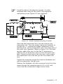
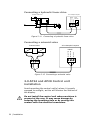
Autopilot Computer
AP24 Control Unit
NET-L
NET-H
SPARE
BLUE
YELLOW
NET-S
RED
J2
BLACK
J1
NET-C
SIMNET
SimNet
Figure 2-4 Control unit connection
J1 and J2 are the SimNet connectors.
2.6 Rudder feedback installation
The RF300 and RF25 Rudder feedback units mount close
to the rudder, and are mechanically linked to the rudder
tiller arm or rudder quadrant. Refer to Figure 2-5 for the
recommended mounting arrangement.
Do not remove the transmitter lever from the feedback
unit. The unit is factory adjusted and need no further
adjustment at installation than described below.
Turn the helm wheel to set the rudder tiller arm to
approximate centre position.
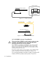
Set the mounting location to be in accordance with Figure
2-5. The centre of the feedback unit should be in line
with the centre of the rudder post. Mount the feedback
unit to a suitable platform using the screws provided. If
necessary, add blocking material under the feedback unit
to adjust the height of the transmitter lever to be level
with the rudder tiller arm.
Due to space limitations, it may be necessary to cut the
length of the transmitter rod to move the feedback unit
closer to the rudder post.
Rotate the feedback transmitter lever to centre position.
(Use the alignment mark to line up the transmitter lever
to be opposite the cable entry into the feedback).
14 | Installation