1
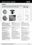
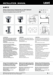
INSTALLATION · MANUAL
4.0282
Schwimmbad-Scheinwerfer aus V4A-Edelstahl mit Einbaugehäuse
Swimmingpool-Light made V4A-stainless steel 316L with built-in pot
Projecteur de piscine en acier inoxydable V4A avec boîtier d‘encastrement
V4A
IP68 EDELSTAHL
5M
KABEL
INKL
INKL
EPOL
12 V
NTC
CONTROL
66
240
140
182
166
240
3
196
206
170
89
1. Anwendung
Einbau-Unterwasser-Scheinwerfer zur Beleuchtung und Akzentuierung in großen Schwimmbädern, Wasserattraktionen und
Springbrunnen.
Der Scheinwerfer ist für einen Einsatz bis 5,0 m Wassertiefe
geeignet. Die Konstruktion ist komplett aus V4A-Edelstahl 1.4571
gefertigt und zusätzlich epoliert. Die Verwendung des Scheinwerfers
in Süßwasser, chloriertem Schwimmbadwasser und in Meerwasser
ist möglich.
Scheinwerfer ist vor Einfrieren zu schützen, das Wasser muss frei von
Metall angreifenden Bestandteilen sein.
Einbaugehäuse ist zur Installation erforderlich und ist je nach
Einbauart auszuwählen,
Zubehörteile (z.B. Betriebsgeräte) sind optional lieferbar.
Achtung! Betrieb nur Unterwasser. Angeschlossene Spezialkabel
sind nicht zu entfernen oder zu kürzen, längere Kabellängen >3 m
lieferbar.
Von jeglichen Kabelverbindungen im Einbaugehäuse bzw. im
Kabelrohr wird abgeraten.
Für die gesamte lichttechnische Anlage wird eine Überspannungsschutzeinheit und die Verwendung eines Trenntrafos zur sicheren
elektrischen Trennung (Schutztrennung) empfohlen.
Sonderkonstruktionen-/anwendungen auf Anfrage.
1. Application
Installed underwater spotlights for lighting and accentuation in large
swimming pools, water attractions and fountains.
The spotlight is suitable for use in water up to 5.0 m deep. It is made
entirely of V4A stainless steel 1.4571 and is also electropolished. The
spotlight can be used in fresh water, chlorinated swimming pool water
and in salt water.
The spotlight must be protected from freezing, and the water must be free
of metal-corroding components.
An installation housing is required for installation and must be selected for
the type of installation.
Accessories (e.g. operating devices) can be supplied optionally.
1. Application
Projecteur immergé encastrable pour l‘éclairage et la mise en valeur de
grandes piscines, d‘attractions aquatiques et de fontaines.
Le projecteur convient pour une installation jusqu‘à une profondeur de
5 m. Construction entièrement réalisée en acier inoxydable électropoli V4A
1.4571. Le projecteur peut être utilisé dans l‘eau douce, l‘eau de piscine
chlorée et dans l‘eau de mer.
Protéger le projecteur contre le gel, l‘eau doit être exempte d‘éléments
agressifs pour les métaux.
Le boîtier d‘encastrement est nécessaire pour l‘installation et doit être
sélectionné en fonction du type de montage,
Les accessoires (p. ex. blocs d‘alimentation) sont disponibles en option.
Attention! Operation only underwater. Connected special cables
must not be removed or shortened; longer cable lengths >3 m can be
supplied.
Cable connections in the installation housing or conduit are not recommended.
A surge protection unit and use of an isolating transformer for secure
electrical disconnection (protective separation) are recommended for the
entire technical lighting system.
Attention! Fonctionnement immergé uniquement. Ne pas enlever ni
raccourcir les câbles spéciaux raccordés, longueurs de câbles > 3 m livrables.
Tous raccords de câbles dans le boîtier d‘encastrement ou dans la gaine de
câbles sont déconseillés.
Special designs/applications on request.
Constructions/applications spéciales sur demande.
2. Technische Daten/Konstruktion
· Scheinwerfer komplett aus V4A-Edelstahl 1.4571 EPOL
· Schutzart IP68 – Wassertiefe 5m
· Runde Aufsatzblende aus V4A-Edelstahl (Höhe 3 mm, ø 240 mm)
· mit 24 POW-LED (total 62 W), 12 V-DC
· mit 24 POW-LED dimmbar (total 62 W), 12 V-DC
· mit 24 POW-LED (total 35 W), 12 V-DC
· kaltweiss (6.000K), neutralweiss (4.500K), warmweiss (3.000K), royalblau
· mit 15 Multichip POW-LED RGB (all on 115 W), 12 V-DC
· mit 12 Multichip POW-LED RGB-W (all on 110 W), 12 V-DC
· POW LED Platine temperaturüberwacht (onboard)
· speziell für Schwimmbadausleuchtung angepasste Lichtverteilung„Multiflux“
· Lieferung mit 3 m Spezial-Unterwasserkabel
· Konstantstromnetzteil oder RGB Controler separat bestellen
· Einbaugehäuse entsprechend der Einbausituation separat bestellen
2. Technical Details/Construction
· Spotlight, entirely made of V4A stainless steel 1.4571 EPOL
· Protection class IP68 – Water depth 5 m
· Round attachment cover, V4A stainless steel, (H3 mm, ø 240 mm
· with 24 POW-LED (total 62 W), 12 V-DC
· with 24 POW-LED dimmable (total 62 W), 12 V-DC
· with 24 POW-LED (total 35 W), 12 V-DC
· coldwhite (6.000 K), neutralwhite (4.500 K), warmwhite (3.000 K), royalblue
· with 15 Multichip POW-LED RGB (all on 115 W), 12 V-DC
· with 12 Multichip POW-LED RGB-W (all on 110 W), 12 V-DC
· POW-LED-Platine temperature control (onboard)
· light distribution especially for swimming pool lighting „Multiflux“
· Supplied with 3 m of special underwater cable
· Constant-current power source/RGB controller ordered separately
· housing, depending on the installation situation must be ordered separately
2. Caractéristiques techniques/Construction
· Projecteur complet en acier inoxydable électropoli V4A 1.4571
· Indice de protection IP68 – Profondeur d‘immersion jusqu‘à 5m
· enjoliveur rond en acier inoxydable V4A (H3 mm, ø 240 mm)
· avec 24 POW-LED (total 62 W), 12 V-DC
· avec 24 POW-LED dimmable (total 62 W), 12 V-DC
· avec 24 POW-LED (total 35 W), 12 V-DC
· blanc froid (6.000 K), blanc neutre (4.500 K), blanc chaud (3.000 K), bleu royal
· avec 15 Multichip POW-LED RGB (all on 115 W), 12 V-DC
· avec 12 Multichip POW-LED RGB-W (all on 110 W), 12 V-DC
· platine POW-LED à température contrôlée (onboard)
· Diffusion de lumière adaptée spécialement à l‘éclairage des piscines (Multiflux)
· Livré avec câble submersible spécial raccordé de 3 m
· Bloc d‘alimentation en courant continu ou contrôleur RVB commander séparément
· Sélectionner le boîtier d‘encastrement adapté selon le type et la situation de montage
WIBRE Elektrogeräte Edmund Breuninger GmbH & Co. KG · Liebigstrasse 9 · 74211 Leingarten/Germany
Telefon: +49 (0) 7131 9053-0 · Telefax: +49 (0) 7131 9053-19 · E-Mail: [email protected]
Une unité anti-surtension et l‘utilisation d‘un transformateur sectionneur
permettant un sectionnement électrique sûr (sectionnement de protection)
sont recommandées pour l‘ensemble de l‘installation d‘éclairage technique.
1/6
INSTALLATION · MANUAL
IP68
dichtgeschweißt
IP68 welded
IP68 oudé
45°
Edelstahlwand
stainless steel wall
mur en acier
TOP/OBEN
3.2
Mörtel
mortar
mortier
eingelegte Folie
fitted foil
revêtement
Beton
intérieur
concrete
béton
ø 170 mm
ø 206 mm
Fliesen
tiles
carreaux
Druckflansch
pressure flange
flasque de
pression
Beton
concrete
béton
3.4
Klebe-/
Folienanstrich
adhesive/
foil coating
revêtement collé/
liner
Klebeflansch
adhesive flange
flasque de collage
Beton
concrete
béton
ø 206 mm
Dichtung
Seal
Joint
ø 5,5 mm
TK 1
3.6
82 m
m
ø 4,5 mm
170 mm
ø 180 mm
3.1
3. Installation/Montage
Zur Installation sind die nationalen Sicherheitsvorschriften zu
beachten. Es wird keine Haftung für unsachgemäßen Einsatz oder
Montage übernommen. Bei nachträglichen Änderungen an den
Leuchten wird keine Haftung übernommen.
Montage des Scheinwerfers in Verbindung mit entsprechendem
Einbaugehäuse aus V4A-Edelstahl mit 1,5 m Kabelschutzrohr für
den Wand- und Bodeneinbau in Betonbecken mit Fliesenauskleidung (max. 30 mm Fliesen-/Mörtelaufbau oder nach Anfrage),
Edelstahlbecken zum Einschweißen, Becken mit eingelegter Folie
oder dünnwandige Becken (Druckflansch) und Becken mit Klebe-/
Folienanstrich (Klebeflansch) möglich.
Montage in Betonbecken
Einbaugehäuse an vorderer Verschalung (Wasserseite) nach Markierung ausrichten und mittels den 3 Halteelementen fixieren. Die richtige Ausrichtung (laut Zeichung 3.2.) des Einbaugehäuses an der
Schalwand ist für den späteren Einbau des Scheinwerfer unbedingt
zu beachten. Gegebenenfalls äußeren Bund z.B. mit Silikon abdichten um das Eindringen von Schmutz ins Innere des Einbaugehäuses
zu vermeiden. Kunststoffabschlussstück an der hinteren Verschalung
fixieren. Das Einbaugehäuse, das Kabelschutzrohr, die Schellen und
das Kunststoffabschlussstück auf festen Halt prüfen. 3.1./3.2.
Nach dem Betonieren und Entfernen der Verschalung Mörtel
und Fliesen bis max. zum Aussendurchmesser (ø 206 mm) des
Einbaugehäuses auftragen. Maximaler Mörtel- und Fliesenaufbau
30mm. Bei höherem Fliesen/-Mörtelaufbau nach Absprache längere
Befestigungsschrauben aus V4A Edelstahl verwenden. 3.3.
Montage in Edelstahlbecken
Positionierung der Leuchten festlegen und Öffnungen von ø 206 mm
in Schwimmbeckenwand entsprechend ausschneiden. Einbaugehäuse
nach Markierung ausrichten und bauseits fixieren. Kunststoffabschlussstück am Ende des Kabelschutzrohres fixieren.
Die richtige Ausrichtung (laut Zeichung 3.2.) des Einbaugehäuses
an der Schalwand ist für den späteren Einbau des Scheinwerfer unbedingt zu beachten. Einbaugehäuse, Kabelschutzrohr mit Schellen
und Kunststoffabschlussstück auf festen Halt prüfen.
Gehäuse mit der Schwimmbadwand IP68-dichtschweißen und
Schweißnaht nachträglich erneut passivieren. 3.4.
2/6
max 30 mm
3.3
Dichtung
Seal
Joint
3. Installation/Mounting
When installing, observe the national safety regulations. We are not liable
for any improper use or installation. No liability will be accepted in case of
subsequent modification to the lights.
Installation of the spotlight in combination with the corresponding installation housing made of V4A stainless steel with 1.5 m cable protection
conduit for wall and floor installation in concrete pools with tile covering
(max. 30 mm tile/mortar thickness, or after consultation with us), for
welding into stainless steel pools, in pools with fitted foil or thin-wall pools
(pressure flange) and pools with adhesive/foil coatings (adhesive flange).
Installation in concrete pools
Align installation housing on the front cover (water side) according to the
marking and fix it with the 3 holding elements. Correct orientation (in
accordance with drawing 3.2.) of the installation housing on the boarded
panel is essential for later installation of the spotlight. If necessary, seal
the outside connection with silicone, for example, to keep dirt from
penetrating inside the installation housing. Fasten plastic end piece to the
rear cover. Check the installation housing, cable protective conduit, clamps
and plastic end piece for firm hold. 3.1./3.2.
After cementing it in and removing the cover, apply mortar and tiles to no
more than the inside diameter (dia. 206 mm) of the installation housing.
Maximum mortar and tile thickness 30mm. In case of higher tile/mortar
thickness, after consultation use longer fastening screws made of V4A
stainless steel. 3.3.
Installation in stainless steel pools
Determine positioning of the lights and cut out openings of dia.206 mm
in the swimming pool wall accordingly. Align and fasten installation
housing on the marking. Fasten plastic end piece at the end of the cable
protection tube.
Correct orientation (in accordance with drawing 3.2.) of the installation
housing on the boarded panel is essential for later installation of the
spotlight. Check installation housing, cable protection tube with clamps
and plastic end piece for firm hold.
Weld housing to the swimming pool wall IP68-tight and then passivate
the welding seam again. 3.4.
3.5
Folie
foil
liner
ø 5,5 mm
3.7
3. Installation/Montage
Respecter les prescriptions nationales applicables en matière de sécurité.
Nous déclinons toute responsabilité pour l’utilisation ou le montage non conforme. De même, nous réfutons toute responsabilité pour les modifications
réalisées sur les luminaires.
Possibilité de montage du projecteur en association avec le boîtier
d‘encastrement correspondant en acier inoxydable V4A avec gaine de
protection pour câble de 1,5 m pour le montage dans la paroi ou le sol des
bassins en béton carrelé (hauteur max. carreaux/mortier 30 mm ou sur
demande), des bassins en acier inoxydable (à souder), des bassins avec
revêtement intérieur (flasque de pression) et des bassins à revêtement collé/
liner (flasque de collage).
Montage dans les bassins en béton
Aligner le boîtier d‘encastrement sur le coffrage avant (côté eau) suivant
le marquage et le fixer au moyen des 3 éléments de maintien. Il faut
impérativement respecter le bon alignement (suivant le schéma 3.2.) du
boîtier d‘encastrement sur la paroi du coffrage pour y monter ultérieurement le projecteur. Le cas échéant, étanchéifier l‘embase extérieure, par
exemple avec du silicone afin d‘éviter que des salissures n‘entrent dans le
boîtier d‘encastrement. Fixer l‘embout d‘extrémité en plastique au coffrage
postérieur. Vérifier la bonne tenue du boîtier d‘encastrement, de la gaine de
protection du câble, des colliers et de l‘embout en plastique. 3.1./3.2.
Après avoir bétonné le bassin puis retiré le coffrage, appliquer le mortier et
poser les carreaux au maximum jusqu‘au diamètre extérieur (D 206 mm)
du boîtier d‘encastrement. Hauteur maximale mortier et carreau 30 mm. Si
la structure carrelée ou enduite de mortier est plus haute et après nous avoir
consultés, utiliser des vis de fixation plus longues en inox V4A. 3.3.
Montage dans des bassins en inox
Déterminer la position des projecteurs et découper des ouvertures correspondantes d‘un diamètre (D) de 206 mm dans la paroi du bassin. Positionner
et fixer le boîtier d‘encastrement selon le marquage indiqué. Fixer l‘embout
d‘extrémité en plastique à l‘extrémité de la gaine de protection du câble.
Il faut impérativement respecter le bon alignement (suivant le schéma
3.2.) du boîtier d‘encastrement sur la paroi du coffrage pour y monter ultérieurement le projecteur. Vérifier la bonne fixation du boîtier d‘encastrement,
de la gaine de protection du câble avec colliers et de l‘embout d‘extrémité
en plastique.
Souder le boîtier sur la paroi du bassin de manière à assurer l‘étanchéité puis
re-passiver le cordon de soudure. 3.4.
WIBRE Elektrogeräte Edmund Breuninger GmbH & Co. KG · Liebigstrasse 9 · 74211 Leingarten/Germany
Telefon: +49 (0) 7131 9053-0 · Telefax: +49 (0) 7131 9053-19 · E-Mail: [email protected]
INSTALLATION · MANUAL
5.0670.02.72
1
2
prim
230 V
500 mm
max 40 m
Mörtel
mortar
mortier
Fliesen
tiles
carreaux
3.8
196
Netzteil
Power supply
Alimentation
3.10
5.0670.04.72
3.9
5.0670.09.45, 5.0670.09.52
1
2
3
4
prim
prim
230 V
230 V
max 40 m
max 40 m
89
RGBX
3.8
3.9
3.9
Montage in Becken mit Klebe-/Folienanstrich
Einbaugehäuse mit Klebeflansch an der vorderen Verschalung
(Wasserseite) nach Markierung ausrichten und fixieren. Die richtige
Ausrichtung (laut Zeichung 3.2.) des Einbaugehäuses an der Schalwand ist für den späteren Einbau des Scheinwerfer unbedingt zu
beachten. Gegebenenfalls äußeren Bund z.B. mit Silikon abdichten
um das Eindringen von Schmutz ins Innere des Einbaugehäuses zu
vermeiden. Kunststoffabschlussstück an der hinteren Verschalung
fixieren. 3.1.
Einbaugehäuse, Kabelschutzrohr mit Schellen und Kunststoffabschlussstück auf festen Halt prüfen.
Nach dem Betonieren und Entfernen der Verschalung Klebe-/Folienanstrich bis Innenkante des Einbaugehäuses auftragen.
Achtung: Die 2 Befestigungsschraublöcher zu späteren
Scheinwerfermontage müssen freigehalten werden. Gegebenenfalls
muss der Klebeflansch zur Haftverbesserung vorbehandelt werden.
Dies ist der Gebrauchsanleitung des verwendeten Materials zu
entnehmen. 3.5.
Installation in pools with adhesive/foil coating
Orient the installation housing on the front cover (water side) according
to the marking and fix it in place. Correct orientation (in accordance
with drawing 3.2.) of the installation housing on the boarded panel is
essential for later installation of the spotlight. If necessary, seal the outside
connection with silicone, for example, to keep dirt from penetrating inside
the installation housing. Fasten plastic end piece to the rear cover. 3.1.
Montage dans les bassins avec revêtement
collé/liner
Aligner et fixer le boîtier d‘encastrement avec le revêtement collé sur le coffrage avant (côté eau) en suivant le marquage. Il faut impérativement respecter
le bon alignement (suivant le schéma 3.2.) du boîtier d‘encastrement sur la
paroi du coffrage pour y monter ultérieurement le projecteur. Le cas échéant,
étanchéifier l‘embase extérieure, par exemple avec du silicone, afin d‘éviter
que des salissures n‘entrent dans le boîtier d‘encastrement. Fixer l‘embout
d‘extrémité en plastique au coffrage postérieur. 3.1.
Montage in Becken mit eingelegter Folie oder
dünnwandigen Becken (Druckflansch)
Einbaugehäuse an vorderen Verschalung (Wasserseite) nach
Markierung ausrichten und fixieren. Die richtige Ausrichtung (laut
Zeichnung 3.2.) des Einbaugehäuses an der Schalwand ist für
den späteren Einbau des Scheinwerfer unbedingt zu beachten.
Gegebenenfalls äußeren Bund z.B. mit Silikon abdichten um das Eindringen von Schmutz in Innere des Einbaugehäuses zu vermeiden.
Kunststoffabschlussstück an der hinteren Verschalung fixieren.3.1.
Einbaugehäuse, Kabelschutzrohr mit Schellen und Kunststoffabschlussstück auf festen Halt prüfen.
Nach dem Betonieren und Entfernen der Verschalung Folie einlegen
und entsprechend am Einbaugehäuse aussparen (8 Löcher 4,5 mm
für Schrauben auf TK 182 und 1 Loch ø 170 mm für Scheinwerfer).
3.7.
Einbaugehäuse, Dichtung, Folie, Dichtung, Druckflansch, 8 Schrauben gleichmäßig auflegen, Falten in der Folie vermeiden und mit 2,6
Nm kreuzweise anziehen. 3.6.
Installation in pools with fitted foil or thinwalled pools (pressure flange)
Orient the installation housing on the front cover (water side) according
to the marking and fix it in place. Correct orientation (in accordance
with drawing 3.2.) of the installation housing on the boarded panel is
essential for later installation of the spotlight. If necessary, seal the outside
connection with silicone, for example, to keep dirt from penetrating inside
the installation housing. Fasten plastic end piece to the rear cover 3.1.
Check installation housing, cable protection tube with clamps and plastic
end piece for firm hold.
After cementing in the installation housing and removing the cover, apply
adhesive/foil coating up to the inside edge of the installation housing.
Attention: The 2 fastening screw holes must be kept free for later
mounting of the spotlight. It may be necessary to pretreat the adhesive
flange for improved adhesion. This can be taken from the instructions for
the material used. 3.5.
Check installation housing, cable protection tube with clamps and plastic
end piece for firm hold.
After cementing in the installation housing and removing the cover, insert
foil and open corresponding cutouts on the installation housing (eight 4.5
mm holes for screws on TK 182 and one 170 mm hole for spotlight). 3.7.
Evenly apply 8 screws to installation housing, seal, foil, seal, pressure
flange, avoiding folds in the foil, and tighten crosswise to 2,6 Nm. 3.6.
WIBRE Elektrogeräte Edmund Breuninger GmbH & Co. KG · Liebigstrasse 9 · 74211 Leingarten/Germany
Telefon: +49 (0) 7131 9053-0 · Telefax: +49 (0) 7131 9053-19 · E-Mail: [email protected]
Vérifier la bonne fixation du boîtier d‘encastrement, de la gaine de protection
du câble avec colliers et de l‘embout d‘extrémité en plastique.
Après avoir bétonné le bassin puis retiré le coffrage, poser le revêtement collé/
liner jusqu‘au bord intérieur du boîtier d‘encastrement.
Attention: Les 2 trous filetés de fixation doivent être laissés libres pour
y monter plus tard le projecteur. Le cas échéant, le flasque de collage devra
être prétraité afin d‘améliorer l‘adhésion. Vous trouverez ces informations
dans la notice d‘utilisation du matériau utilisé. 3.5.
Montage dans les bassins avec revêtement intérieur ou à parois minces (flasque de pression)
Aligner et fixer le boîtier d‘encastrement sur le coffrage avant (côté eau) en
suivant le marquage. Il faut impérativement respecter le bon alignement
(suivant le schéma 3.2.) du boîtier d‘encastrement sur la paroi du coffrage
pour y monter ultérieurement le projecteur. Le cas échéant, étanchéifier
l‘embase extérieure, par exemple avec du silicone afin d‘éviter que des
salissures n‘entrent dans le boîtier d‘encastrement. Fixer l‘embout d‘extrémité
en plastique au coffrage postérieur. 3.1.
Vérifier la bonne fixation du boîtier d‘encastrement, de la gaine de protection
du câble avec colliers et de l‘embout d‘extrémité en plastique.
Après avoir bétonné le bassin puis retiré le coffrage, mettre le revêtement en
place et réaliser une ouverture au niveau du boîtier d‘encastrement
(8 trous de diamètre 4,5 mm sur TK 182 et 1 trou de diamètre 170 mm pour
le projecteur). 3.7.
Positionner régulièremeent le boîtier d‘encastrement, le joint, le revêtement,
le flasque de pression, les 8 vis, éviter les plis dans le revêtement et serrer en
croix à 2,6 Nm. 3.6.
3/6
5.0670.12.72
230 V
– +
dimm
prim
2
dimm
1
Anschlußeinheit
Connection Unity
Raccordement
M
M isc
sa ixin hbe
cm g u
él bag tel
an
ge
ur
INSTALLATION · MANUAL
max 40 m
3.9
Zugentlastung
Cable anchorage
Décharge de traction
Überwurfmutter
Cap nut
Écrou
Dichteinsatz
Seal insert
Joint
Verguß
Sealing
Scellement
Schraube
Screw
Vis
Deckel
Cover
Couvercle
Dichtung
Seal
Joint
Auffüllen Vergußhöhe
Height of filling
Niveau de scellement
3.11
Achtung: Anschluss der Netzteile muss stromlos erfolgen,
da sonst Entladungen im Netzteil zur Schädigung der LED führen
können. Es darf keine Primärspannung anliegen.
Achtung: Werden weniger als 4 Scheinwerfer angeschlossen, ist
die Reihenfolge der Ausgangskanäle zu beachten, beim Anschluss
von nur 3 Scheinwerfern werden also die Kanäle 1 bis 3 benutzt, bei
2 Scheinwerfern die Kanäle 1 bis 2 und so weiter.
Hinweis: Die Installation eines bauseitigen Überspannungsschutzes
nach DIN VDE 0100-443, DIN VDE 0100-534 und EN 62305 wird empfohlen.
Attention: The power supply must be connected without power,
since otherwise discharges in the power supply unit may damage
the LED. Primary voltage must not be present.
Attention: If less than 4 spotlights are connected, the sequence
of the output channels must be observed; if only 3 spotlights are
connected, channels 1 to 3 are used, if 2 spotlights are connected
channels 1 to 2 are used, and so on.
Note: Installation of customised surge protection in accordance with
DIN VDE 0100-443, DIN VDE 0100-534 and EN 62305 is recommended.
Attention: Les blocs d‘alimentation doivent être raccordés hors tension, sinon des décharges dans le bloc d‘alimentation peuvent détériorer
les LED. Aucune tension primaire ne doit être présente.
Attention: Si on raccorde moins de 4 projecteurs, il faut suivre l‘ordre
des canaux de sortie. Si on raccorde seulement 3 projecteurs, on utilise par
conséquent les canaux 1 à 3, 2 projecteurs les canaux 1 à 2 et ainsi de suite.
Remarque: L‘installation d‘un système anti-surtension local
conforme aux normes DIN VDE 0100-443, DIN VDE 0100-534 et EN 62305
est recommandée.
Montage des Scheinwerfers
Das UW-Kabel durch die innenliegende Kabelverschraubung des Einbaugehäuses in das Kabelschutzrohr einführen und ca. 1,5 m Kabel
im Einbaugehäuse einwickeln. Die Kabelverschraubung festziehen,
damit das Kabel abgedichtet wird. 3.10.
Den Scheinwerfer einsetzen, ausrichten und festschrauben. Bei
falsch ausgerichtetem Einbau des Einbaugehäuses muss ein Ausgleichsadapterring optional vorgesehen werden (auf Anfrage)
Installing the spotlight
Guide the UW cable through the inside cable fitting of the installation
housing and into the cable protection conduit and wrap approx. 1.5 m of
cable inside the installation housing. Tighten the cable fitting firmly to seal
the cable. 3.10.
Montage du projecteur
Rentrer le câble UW par le presse-étoupe du boîtier d‘encastrement dans
la gaine de protection du câble et enrouler environ 1,5 m de câble dans le
boîtier d‘encastrement. Bloquer le presse-étoupe pour étanchéifier le câble.
3.10.
Insérer, ajuster et fixer le projecteur. En cas de montage mal aligné du boîtier
d‘encastrement, il faut prévoir une bague d‘adaptation d‘équilibrage en
option (sur demande).
Visser le raccord à vis M20 en plastique fourni au niveau de l‘embout
d‘extrémité en plastique et serrer l‘écrou-raccord afin d‘étanchéifier le câble.
3.8.
Am Kunststoffabschlussstück beiliegende Kunststoffverschraubung
M20 einschrauben und Überwurfmutter festziehen, damit das Kabel
abgedichtet wird. 3.8.
Insert the spotlight, align and tighten it. If the installation housing is
installed with incorrect orientation, a compensating adapter ring must be
planned for as an option (on request)
Screw the accompanying M20 plastic fitting onto the plastic end piece and
tighten the lock nut so that the cable is sealed. 3.8.
Attention: utiliser uniquement les câbles raccordés en usine. Indiquer
la longueur de câble souhaitée lors de la commande.
Achtung: Nur werkseitig angeschlossenes Kabel verwenden.
Gewünschte Kabellänge bei Bestellung angeben.
Einzelanschlussader entsprechend den Vorschriften an den Netzteilen elektrisch anschließen. 3.9.
Die maximale Anzahl von Leuchten und Anschlußart siehe auch
Manual des entsprechenden Netzteiles oder RGB(W) Controlers.
Hinweis: Bei nicht werkseitig angeschlossenem Kabel siehe
Punkt 4.
Attention: Use only cable connected at the factory. Specify desired
cable length when ordering.
Connect individual wires to the power supply according to the regulations.
3.9.
For the maximum number of lights and connection type, also see the
manual of the corresponding power supply unit or RGB(W) controllers.
Note: If the cable is not connected at the factory, see point 4.
Remarque: Si le câble n‘a pas été raccordé en usine, voir le point 4.
4. Kabelanschluß, Verguß und Wartung
Bei nicht werksseitig angeschlossenem und vergossenem Kabel, das
UW-Kabel durch die innenliegende Kabelverschraubung des Einbaugehäuses in das Kabelschutzrohr einführen und ca. 1,5 m Kabel im
Einbaugehäuse belassen. Die Kabelverschraubung festziehen, damit
das Kabel abgedichtet wird. 3.10.
Am Scheinwerfer rückseitig den Anschlußeinheit öffnen. das Kabel
durch die Kabelverschraubung am Scheinwerfer einführen, entsprechend an den Anschlussklemmen am Scheinwerfer anschließen,
Zugentlastung anschrauben, die Kabelverschraubung verschließen
und die komplette Anschlusseinheit mit Vergußmasse vergießen.
Danach den Deckel mit Dichtung wieder fest verschrauben. 3.11.
Hinweis: Vergußmasse 9.9011.00.25 ausreichend für 2 Scheinwerfer. Bitte separat bestellen.
4. Cable connection, sealing compound
and maintenance
If the cable was not connected and sealed at the factory, guide the UW
cable through the inside cable fitting of the installation housing and into
the cable protection conduit and wrap approx. 1.5 m of cable inside the installation housing. Tighten the cable fitting firmly to seal the cable. 3.10.
Open the connection unit on the back of the spotlight, guide the cable
through the cable fitting on the spotlight, connect it accordingly to the
connection terminals, screw on the tension relief, seal the cable fitting
and seal the complete connection unit with sealing compound. After that,
screw the cover with seal back on tight. 3.11.
4. Raccordement du câble,
scellement et maintenance
CRentrer le câble UW à travers le presse-étoupe intérieur du boîtier
d‘encastrement dans la gaine du câble et enrouler environ 1,5 m de câble
du boîtier d‘encastrement dans la gaine de protection du câble . Bloquer le
presse-étoupe pour étanchéifier le câble. 3.10.
Ouvrir l‘unité de raccordement au dos du projecteur, amener le câble jusqu‘au
projecteur à travers le presse-étoupe, le raccorder en conséquence aux bornes
de branchement du projecteur, visser la pince de décharge de traction, fermer
le presse-étoupe et sceller toute l‘unité de raccordement avec le masse de
scellement. Revisser ensuite le couvercle à bloc avec le joint. 3.11.
Note: Sealing compound 9.9011.00.25 sufficient for 2 spotlights. Please
order separately.
Remarque: Masse de scellement 9.9011.00.25 suffisant pour
2 projecteurs. A commander séparément.
Scheinwerfer wie oben beschrieben einbauen.
Verunreinigungen und Ablagerungen auf Glas oder Edelstahlteilen
sind mit handelsüblichen Reinigungsmitteln zu entfernen.
Install spotlight as described above.
Soiling and deposits on glass or stainless steel parts must be removed with
standard cleaning agents.
Monter le projecteur comme décrit plus haut.
Les impuretés et les dépôts sur le verre ou les pièces en acier inoxydable
doivent être éliminés à l‘aide d‘un détergent classique.
Achtung: Ein Montageabstand von 10 cm zwischen Betriebsgeräten wird dringend empfohlen, um wechselseitiges Erhitzen zu
vermeiden.
Attention: A mounting distance of 10 cm between various
power supplies is strongly recommended, in order to avoid mutual
heating.
Attention: Une distance de montage de 10 cm entre plusieurs
alimentations est vivement conseillé pour éviter une chauffe
mutuelle !
Hinweis: Nur Edelstahlwerkzeug verwenden!
Zur Vermeidung von Fremdrost!
Note: Only use tools made of stainless steel!
To avoid extraneous rust!
Remarque: L‘utilisation d‘outils en acier inoxydable est obligatoire! Pour éviter que la corrosion se forme!
WIBRE Elektrogeräte Edmund Breuninger GmbH & Co. KG · Liebigstrasse 9 · 74211 Leingarten/Germany
Telefon: +49 (0) 7131 9053-0 · Telefax: +49 (0) 7131 9053-19 · E-Mail: [email protected]
Raccorder les différents conducteurs aux blocs d‘alimentation conformément
aux prescriptions. 3.9.
Pour le nombre maximal d‘ampoules et le type de raccordement, voir aussi le
manuel du bloc d‘alimentation concerné ou les contrôleurs RVB(B).
4/6
INSTALLATION · MANUAL
Scheinwerfer · Spotlight · Projecteur
4.0282.00.11
24 POW-LED cold white
4.0282.00.12
24 POW-LED warm white
4.0282.00.13
24 POW-LED neutral white
4.0282.00.16
24 POW-LED royal blue
4.0282.00.19
15 Multichip POW-LED RGB
4.0282.00.41
12 Multichip POW-LED RGB-CW
4.0282.00.42
12 Multichip POW-LED RGB-WW
4.0282.00.43
12 Multichip POW-LED RGB-NW
4.0282.00.44
12 Multichip POW-LED RGB-A
4.0282.00.21
24 POW-LED cold white
4.0282.00.22
24 POW-LED warm white
4.0282.00.23
24 POW-LED neutral white
4.0282.00.26
24 POW-LED royal blue
4.0282.00.01
24 POW-LED cold white
4.0282.00.02
24 POW-LED warm white
4.0282.00.03
24 POW-LED neutral white
4.0282.00.06
24 POW-LED royal blue
4.0282.73.11
4.0282.73.12
4.0282.73.13
4.0282.73.16
4.0282.73.19
4.0282.73.41
4.0282.73.42
4.0282.73.43
4.0282.73.44
4.0282.73.21
4.0282.73.22
4.0282.73.23
4.0282.73.26
4.0282.73.01
4.0282.73.02
4.0282.73.03
4.0282.73.06
24 POW-LED cold white
24 POW-LED warm white
24 POW-LED neutral white
24 POW-LED royal blue
15 Multichip POW-LED RGB
12 Multichip POW-LED RGB-CW
12 Multichip POW-LED RGB-WW
12 Multichip POW-LED RGB-NW
12 Multichip POW-LED RGB-A
24 POW-LED cold white
24 POW-LED warm white
24 POW-LED neutral white
24 POW-LED royal blue
24 POW-LED cold white
24 POW-LED warm white
24 POW-LED neutral white
24 POW-LED royal blue
6.000K
3.000K
4.500K
460nm
total 62 W (5520 lm)
12 V DC
total 62 W (4560 lm)
12 V DC
total 62 W (5160 lm)
12 V DC
total 62 W (650 mW/LED)
12 V DC
all on 115 W
12 V DC
coldwhite: 6000K all on 110 W (coldwhite: 2720 lm) 12 V DC
warmwhite: 3000K all on 110 W (warmwhite: 2095 lm) 12 V DC
neutralwhite: 4500K all on 110 W (neutralwhite: 2385 lm)12 V DC
amber
all on 110 W
12 V DC
6.000K
total 62 W (5520 lm)
12 V DC
3.000K
total 62 W (4560 lm)
12 V DC
4.500K
total 62 W (5160 lm)
12 V DC
460nm
total 62 W (650 mW/LED)
12 V DC
6.000K
total 35 W (3840 lm)
12 V DC
3.000K
total 35 W (3000 lm)
12 V DC
4.500K
total 35 W (3360 lm)
12 V DC
460nm
total 35 W (525 mW/LED)
12 V DC
30°-120° Multiflux
30°-120° Multiflux
30°-120° Multiflux
30°-120° Multiflux
45°-120° Multiflux
45°-120° Multiflux
45°-120° Multiflux
45°-120° Multiflux
45°-120° Multiflux
30°-120° Multiflux
30°-120° Multiflux
30°-120° Multiflux
30°-120° Multiflux
90°
90°
90°
90°
(2x4,0 qmm)
(2x4,0 qmm)
(2x4,0 qmm)
(2x4,0 qmm)
(2x4,0 + 4x0,5 qmm)
(2x4,0 + 4x0,5 qmm)
(2x4,0 + 4x0,5 qmm)
(2x4,0 + 4x0,5 qmm)
(2x4,0 + 4x0,5 qmm)
(2x4,0 + 1x1,0 qmm)
(2x4,0 + 1x1,0 qmm)
(2x4,0 + 1x1,0 qmm)
(2x4,0 + 1x1,0 qmm)
(2x4,0 qmm)
(2x4,0 qmm)
(2x4,0 qmm)
(2x4,0 qmm)
6.000K
3.000K
4.500K
460nm
30°-120° Multiflux
30°-120° Multiflux
30°-120° Multiflux
30°-120° Multiflux
45°-120° Multiflux
45°-120° Multiflux
45°-120° Multiflux
45°-120° Multiflux
45°-120° Multiflux
30°-120° Multiflux
30°-120° Multiflux
30°-120° Multiflux
30°-120° Multiflux
90°
90°
90°
90°
(2x4,0 qmm)
(2x4,0 qmm)
(2x4,0 qmm)
(2x4,0 qmm)
(2x4,0 + 4x0,5 qmm)
(2x4,0 + 4x0,5 qmm)
(2x4,0 + 4x0,5 qmm)
(2x4,0 + 4x0,5 qmm)
(2x4,0 + 4x0,5 qmm)
(2x4,0 + 1x1,0 qmm)
(2x4,0 + 1x1,0 qmm)
(2x4,0 + 1x1,0 qmm)
(2x4,0 + 1x1,0 qmm)
(2x4,0 qmm)
(2x4,0 qmm)
(2x4,0 qmm)
(2x4,0 qmm)
total 62 W (5520 lm)
12 V DC
total 62 W (4560 lm)
12 V DC
total 62 W (5160 lm)
12 V DC
total 62 W (650 mW/LED)
12 V DC
all on 115 W
12 V DC
coldwhite: 6000K all on 110 W (coldwhite: 2720 lm) 12 V DC
warmwhite: 3000K all on 110 W (warmwhite: 2095 lm) 12 V DC
neutralwhite: 4500K all on 110 W (neutralwhite: 2385 lm)12 V DC
amber
all on 110 W
12 V DC
6.000K
total 62 W (5520 lm)
12 V DC
3.000K
total 62 W (4560 lm)
12 V DC
4.500K
total 62 W (5160 lm)
12 V DC
460nm
total 62 W (650 mW/LED)
12 V DC
6.000K
total 35 W (3840 lm)
12 V DC
3.000K
total 35 W (3000 lm)
12 V DC
4.500K
total 35 W (3360 lm)
12 V DC
460nm
total 35 W (525 mW/LED)
12 V DC
Einbaugehäuse · installation housing · boîtier d’encastrement
4.0282.01.00
aus V4A-Edelstahl mit 1,5m Kabelschutzschlauch und Abschlussstutzen M20 Kunststoff, für Einbau in Betonbecken mit Fliesenauskleidung
made of V4A stainless steel with 1.5 m protective cable tube and M20 plastic terminating connection, for installation in concrete pools with tile covering
en acier inoxydable V4A avec gaine de protection du câble de 1,5 m et embouts d‘extrémité M20 en plastique, pour le montage dans les bassins en béton carrelé
4.0282.02.00
aus V4A-Edelstahl mit 1,5m Kabelschutzschlauch und Abschlussstutzen M20 Kunststoff, zum Einbau in dünnwandige Becken und folienausgekleidete Becken (Druckflansch ø 244 mm)
made of V4A stainless steel with 1.5m protective cable tube and M20 plastic terminating connection, for installation in thin-walled pools and foil lined pools (pressure flange ø 244 mm)
en acier inoxydable V4A avec gaine de protection du câble de 1,5 m et embouts d‘extrémité M20 en plastique, pour le montage dans des bassins à parois fines et bassins avec liner (flasque de pression ø 244 mm)
4.0282.03.00
aus V4A-Edelstahl mit 1,5 m Kabelschutzschlauch und Abschlussstutzen M20 Kunststoff, für Einbau in Becken mit Klebe-/Folienanstrich (Klebeflansch ø 350 mm)
made of V4A stainless steel with 1.5 m protective cable tube and M20 plastic terminating connection, for installation in pools with adhesive/foil coating (adhesive flange ø 350 mm)
en acier inoxydable V4A avec gaine de protection du câble de 1,5 m et embouts d‘extrémité M20 enplastique, pour le montage dans les bassins à revêtement collé/liner (flasque de collage ø 350 mm)
4.0282.04.00
aus V4A-Edelstahl mit 1,5 m Kabelschutzschlauch und Abschlussstutzen M20 Kunststoff, zum Einschweißen in Edelstahlbecken
made of V4A stainless steel with 1.5 m protective cable tube and M20 plastic terminating connection, for welding into stainless steel pools
en acier inoxydable V4A avec gaine de protection du câble de 1,5 m et embouts d‘extrémité M20 enplastique, pour le soudage dans les bassins en acier inoxydable
Betriebsgeräte · Power Supplies · Alimentation
5.0670.01.72
Konstantstromnetzteil –IP65, 12V-DC, 100W, for 1 Scheinwerfer, nur für 24 POW-LED 700 mA/350 mA monochrom Modul Serie 4.0282/281
Power supply – IP65, 12V-DC, 100W, for 1 spotlight, only for use with 24 POW-LED 700 mA/350 mA monochrom Modul Serie 4.0282/281
Alimentation – IP65, 12V-DC, 100W, für 1 projecteur, a utiliser seulement avec 24 POW-LED 700 mA/350 mA monochrom Modul Serie 4.0282/281
5.0670.02.72
Konstantstromnetzteil – IP20, für Hutschienenmontage, 12V-DC, 70-140W, für 1 - max. 2 Scheinwerfer, Anschluß nur von 24 POW-LED 700 mA/350 mA monochrom Modul Serie 4.0282/281
Power supply – IP20, for H-rail mounting, 12V/DC, 70-140W, for 1 - max. 2 spotlights, connection only of 24 POW-LED 700 mA/350 mA monochrome module series 4.0282/281
Alimentation – IP20, pour montage sur profilé chapeau, 12 V/DC, 70-140W, pour 1 - max. 2 projecteurs, raccordement uniquement d‘un module monochrome 24 POW-LED 700 mA/350 mA série 4.0282/281
5.0670.04.72
Konstantstromnetzteil – IP20, für Hutschienenmontage, 12V-DC, 70-280 W, für 1 - max. 4 Scheinwerfer, Anschluß nur von 24 POW-LED 700 mA/350 mA monochrom Modul Serie 4.0282/281
Power supply – IP20, for H-rail mounting, 12V/DC, 70-280 W, for 1 - max. 4 spotlights, connection only of 24 POW-LED 700 mA/350 mA monochrome module series 4.0282/281
Alimentation – IP20, pour montage sur profilé chapeau, 12 V/DC, 70-280 W, pour 1 - max. 4 projecteurs, raccordement uniquement d‘un module monochrome 24 POW-LED 700 mA/350 mA série 4.0282/281
5.0670.12.72
Konstantstromnetzteil – IP20, für Hutschienenmontage, 12V-DC, 70-140W, dimmbar 1…10 V, Dali, für 1 - max. 2 Scheinwerfer, Anschluß nur von 24 POW-LED 700 mA/350 mA monochrom dimmbar Modul Serie 4.0282/281
Power supply – IP20, for H-rail mounting, 12V/DC, 70-140W, dimmable 1…10 V, Dali, for 1 - max. 2 spotlights, connection only of 24 POW-LED 700 mA/350 mA monochrome dimmable module series 4.0282/281
Alimentation – IP20, pour montage sur profilé chapeau, 12 V/DC, 70-140W, dimmable 1…10 V, Dali, pour 1 - max. 2 projecteurs, raccordement uniquement d‘un module monochrome dimmable 24 POW-LED 700 mA/350 mA série 4.0282/281
5.0670.09.45
RGB-Controler – IP20, für Hutschienenmontage, 700 mA, 12 V-DC, 1-130 W, für max. 1 Scheinwerfer, DMX in/out, Master/Slave, Stand-alone Programme, Anschluß nur von 15 Multichip POW-LED RGB 700 mA Modul Serie 4.0282/4.0281
RGB-Controler – IP20, for H-rail mounting, 700 mA, 12 V-DC, 1-130 W, for max. 1 spotlight, DMX in/out, Master/Slave, Stand-alone programms, connection only of 15 Multichip POW-LED RGB 700 mA module series 4.0282/282
Contrôler RGB – IP20, pour montage sur profilé chapeau, 700 mA, 12 V-DC, 1-130 W, pour max. 1 projecteur, DMX in/out, Master/Slave, Stand-alone programmes, raccordement uniquement d‘un module 15 Multichip POW-LED RGB 700 mA série 4.0282/282
5.0670.09.52
RGB-W-Controler –IP20, für Hutschienenmontage, 12 V-DC, 1-130 W, für max. 1 Scheinwerfer, DMX in/out, Master/Slave, Stand-alone Programme, Anschluß nur von 12 Multichip POW-LED RGB-W Modul Serie 4.0282/4.0281
RGB-W-Controler –IP20, for H-rail mounting, 12 V-DC, 1-130 W, for max. 1 spotlight, DMX in/out, Master/Slave, Stand-alone programms, connection only of 12 Multichip POW-LED RGB-W module series 4.0282/282
Contrôler RGB-B –IP20, pour montage sur profilé chapeau, 12 V-DC, 1-130 W, pour max. 1 projecteur, DMX in/out, Master/Slave, Stand-alone programmes, raccordement uniquement d‘un module 15 Multichip POW-LED RGB-W série 4.0282/282
5/6
WIBRE Elektrogeräte Edmund Breuninger GmbH & Co. KG · Liebigstrasse 9 · 74211 Leingarten/Germany
Telefon: +49 (0) 7131 9053-0 · Telefax: +49 (0) 7131 9053-19 · E-Mail: [email protected]
INSTALLATION · MANUAL
6. Garantiebestimmungen
Folgende Garantiezeiten und Bestimmungen gelten vom Tage der
Lieferung an:
• 24 Monate auf WIBRE-Scheinwerfer.
• Von den Garantieansprüchen ausgenommen sind Leuchtmittel und
LED Einheiten.
• Unter die Garantie fallen nachweisbare Material-, Konstruktionsund Verarbeitungsfehler vonseiten des Herstellers.
• Für Schäden, welche durch Nichtbeachtung dieser Betriebsanleitung, oder durch unsachgemäße Reparatur entstehen, können wir
keine Garantie übernehmen.
• Keine Garantie besteht, wenn die Installation nicht korrekt nach
den Bestimmungen vorgenommen wurde oder bei Verwendung
nicht geeigneter Leuchtmittel bzw. Anschlusskabel.
• Änderungen, die dem technischen Fortschritt dienen,
behalten wir uns vor.
7. Wichtige Hinweise
(Bei Nichtbeachtung folgender Punkte,
entfällt die Garantie.)
• Vor der Installation müssen alle Teile auf Transportschäden
überprüft werden!
• Jegliche Montage-, Installations- und Elektroarbeiten müssen von
qualifiziertem Fachpersonal durchgeführt werden.
• Zur Vermeidung von Fremdrost nur Edelstahlwerkzeug verwenden!
• Die Kabellänge der Leuchten ist so zu wählen, dass man nicht im
Wasser oder feuchten Umgebung verlängern muss. Spätere Reklamationen aufgrund dessen können nicht akzeptiert werden.
• Es dürfen nur originale Wibre-Betriebsgeräte verwendet werden.
• Ein Montageabstand von 10 cm zwischen Betriebsgeräten wird
dringend empfohlen, um wechselseitiges Erhitzen zu vermeiden.
• Anschluss der Betriebsgeräte muss stromlos erfolgen, da sonst
Entladungen im Netzteil zur Schädigung der LED führen können.
Es darf keine Primärspannung beim Wechsel der LED anliegen.
• Beim Anschließen der Leuchte die Polung beachten! Eine falsche
Polung kann dem LED-Modul schaden.
• Die Installation eines bauseitigen Überspannungsschutzes nach
DIN VDE 0100-443, DIN VDE 0100-534 und EN 62305 wird
empfohlen.
• Bitte achten Sie auf Maßnahmen gegen ESD (Elektrostatische
Entladung) während aller Arbeiten am Scheinwerfer, Betriebsgerät
und LED.
5. General maintenance information
• When cleaning, make sure that the lights do not come into contact with
metal-corroding cleaning agents. The use of acid-containing cleaning
agents on or near stainless-steel spotlight parts must always be avoided.
• C lean spotlights and installation housing regularly to avoid extraneous
rust deposits.
• Attention: Do not use high-pressure cleaners.
• P rotect lightbulbs from freezing; they must be removed, if necessary,
or specially protected.
• L ost screws may only be replaced by screws made of V4A.
• D epending on load (wattage) and water quality, we recommend
changing the seals (on the glass pane, fitting, O-ring) and cable
every 5–8 years.
6. Warranty Conditions
The following warranty periods and conditions apply from the day of
delivery:
• 24 months on WIBRE spotlights.
• L amps and LED units are excluded from warranty claims.
• The warranty covers verifiable material, design and work
errors by the manufacturer.
• We cannot accept liability for damages caused by failure to comply with
this operating manual or through improper repair.
• The warranty is void if the installation was not performed properly
according to the instructions or unsuitable lamps
or connecting cables are used.
• We reserve the right to make changes for the
purpose of technical progress.
7. Important information
(If the following points are disregarded,
the guarantee expires.)
• B efore installation, all parts must be checked for transport damage!
• A ll fitting, installation and electrical work must be performed by qualified
specialist staff.
• O nly use stainless steel tools to avoid external rust!
• The cable length of the lights should be chosen in such a way that it is
not necessary to extend in water or moist environments. Later complaints
resulting from this cannot be accepted.
• Only original Wibre operating units may be used.
• A n installation distance of 10 cm between operating devices is urgently
recommended in order to avoid mutual heating up.
• The operating devices must be connected without power, as otherwise
discharges in the power supply may cause the LED to be damaged. No
primary voltage may be applied when changing the LED.
• N ote polarity when changing the lights! The wrong polarity can damage
the LED module.
• It is recommended that the customer install an overvoltage protection in
accordance with DIN VDE 0100-443, DIN VDE 0100-534 and EN 62305.
• P lease comply with all anti-ESD (electrostatic discharge) measures during
all work on the spotlight, operating device and LED.
5. Instructions d‘entretien générales
• Lors du nettoyage, le projecteur ne doit pas entrer en contact avec des
détergents attaquant les métaux. L‘utilisation de détergent à base d‘acide
chlorhydrique sur et à proximité des pièces du projecteur en acier inoxydable
est totalement interdite.
• Nettoyer régulièrement le projecteur et le boîtier d‘encastrement afin d‘éviter
tout dépôt d‘oxydation.
• Attention : Ne pas utiliser de nettoyeur haute pression.
• Protéger les projecteurs contre le gel ; le cas échéant, les démonter ou
assurer une protection spéciale.
• Les vis perdues ne doivent être remplacées que par des vis en acier
inoxydable V4A.
• Selon la sollicitation (puissance) et la qualité de l‘eau, il est recommandé de
procéder au changement des joints (sur les vitres, les raccords vissés et les
joints toriques) et du câble tous les 5 à 8 ans.
6. Conditions de garantie
Les délais et dispositions de garantie suivantes s‘appliquent à compter de la
date de livraison :
• 24 mois sur le projecteur WIBRE.
• Les ampoules et unités à LED sont exclues de la garantie.
• La garantie couvre les défauts de matériaux, les vices de construction et de
traitement dont la preuve est apportée qu‘ils sont imputables au fabricant.
• Les dommages résultant du non-respect de la présente notice d‘utilisation
ou d‘une réparation non conforme, sont exclus de la garantie.
• Nous déclinons toute garantie dans les cas où l‘installation n‘a pas été
effectuée dans les règles de l‘art selon les instructions ou en cas d‘utilisation
d‘ampoules ou de câbles de raccordement non appropriés.
• Nous nous réservons le droit de réaliser toute modification répondant au
progrès technique.
8. Remarques importantes
(La garantie s‘éteint en cas de non-respect
des points suivants)
• L‘absence d‘avaries de transport doit être vérifiée avant l‘installation !
• Tous les travaux de montage et d‘installation, ainsi que les travaux
électriques, doivent être réalisés par du personnel qualifié.
• Afin d‘éviter tout dépôt de rouille, utiliser exclusivement des outils en acier
inoxydable !
• La longueur de câble des lampes doit être choisie de telle sorte à ce qu‘il ne
soit pas nécessaire de la prolonger dans de l‘eau ou dans un environnement
humide. Toute réclamation ultérieure à ce motif ne sera pas acceptée.
• Seuls des équipements Wibre originaux doivent être utilisés.
• Une distance de montage de 10 cm entre les équipements est vivement
recommandée afin d‘éviter un réchauffement mutuel.
• Le raccordement des équipements doit être effectué sans courant, sans
quoi des décharges dans le bloc d‘alimentation pourraient entraîner une
détérioration des LED. Aucune tension primaire ne doit être établie lors du
changement des LED.
• Lors du raccordement des lampes, respecter la polarité ! Une erreur de
polarité peut endommager le module de LED.
• L‘installation d‘une protection contre la surtension par le client conforme
aux normes DIN VDE 0100-443, DIN VDE 0100-534 et
EN 62305 est recommandée.
• Veuillez respecter les mesures contre la décharge électrostatique durant tous
les travaux sur des projecteurs, équipements et LED.
Zubehör · Accessories · Accessoires
9.9011.00.25
Vergußmasse – Mischbeutel, 170 ml, ausreichend für 2 Scheinwerfer
Sealing compound – mixing bag, 170 ml, for 2 spotlights
Masse de scellement – sac mélangeur 170 ml, pour 2 projecteurs
9.0670.65.72
Montagegehäuse – Kunststoff, IP65, mit 1 in/1 out, passend für Netzteil und RGB Controler Serie 4.0282/281
mounting housing – plastic, IP65, with 1 in/1 out, suitable for power supplies and RGB Controler series 4.0282/281
montage de boîtier – plastique, IP65, avec 1 in/1 out, adapté pour alimentations et RVB Contrôler series 4.0282/281
9.6150.02.40
9.6150.04.40
9.6150.04.10
Spezial-Unterwasserkabel – pro m, 2 x 4 qmm, ø 9 mm · Special underwater cable – per m, 2 x 4 qmm, ø 9 mm · Câble spéciaux immergeables – par m, 2 x 4 qmm, ø 9 mm
Spezial-Unterwasserkabel – pro m, 2 x 4 qmm + 4 x 0,5 qmm, ø 11 mm · Special underwater cable – per m, 2 x 4 qmm + 4 x 0,5 qmm, ø 11 mm · Câble spéciaux immergeables – par m, 2 x 4 qmm + 4 x 0,5 qmm, ø 11 mm
Spezial-Unterwasserkabel – pro m, 2 x 4 qmm + 1 x 1,0 qmm · Special underwater cable – per m, 2 x 4 qmm + 1 x 1,0 qmm · Câble spéciaux immergeables – par m, 2 x 4 qmm + 1x 1,0 qmm
6/6
WIBRE Elektrogeräte Edmund Breuninger GmbH & Co. KG · Liebigstrasse 9 · 74211 Leingarten/Germany
Telefon: +49 (0) 7131 9053-0 · Telefax: +49 (0) 7131 9053-19 · E-Mail: [email protected]
W448 Stand 07.15 - Technische Änderungen vorbehalten - Für Druckfehler übernehmen wir keine Haftung
5. Allgemeine Wartungshinweise
• Beim Reinigen darf die Leuchte nicht mit Metall angreifenden Reinigungsmitteln in Berührung kommen. Der Einsatz salzsäurehaltiger Reinigungsmittel an und in der Nähe von Scheinwerferteilen
aus Edelstahl ist in jedem Fall zu unterlassen.
• Scheinwerfer und Einbaugehäuse regelmäßig reinigen, um
Fremdrostablagerungen zu vermeiden.
• Achtung: Keine Hochdruckreiniger verwenden.
• Strahler vor Einfrieren schützen, gegebenenfalls müssen diese
demontiert oder speziell geschützt werden.
• Verloren gegangene Schrauben dürfen nur durch Schrauben aus
V4A ersetzt werden.
• Je nach Beanspruchung (Höhe der Watttage) und Wasserqualität ist
alle 5–8 Jahre ein Wechsel der Dichtungen (Glasscheibe, Verschraubung, O-Ring) und der Kabel zu empfehlen.