1
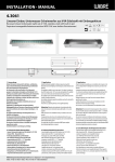
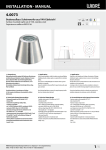
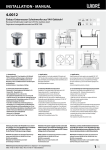
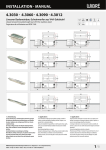
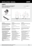
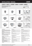
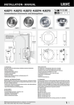
Installation · Manual 4.0199 Schwimmbad-Scheinwerfer aus V4A-Edelstahl mit Einbaugehäuse Swimmingpool-Light made V4A-stainless steel 316L with built-in pot Projecteur de piscine en acier inoxydable V4A avec boîtier d‘encastrement V4A EPOL Gr. 316L Kabel Cable Câble 210 5m 65 3 206 120 183 180 180 120 206 161 210 20 120 1. Anwendung Schwimmbad-Scheinwerfer zur Beleuchtung und Akzentuierung in Schwimmbädern, Whirlpools oder Wasserspielen. Empfohlene Beckengröße (ca. 8 x 5 m) oder nach Absprache. Der Scheinwerfer ist für einen Einsatz bis 5,0 m Wassertiefe geeignet. Die Konstruktion ist komplett aus V4A-Edelstahl 1.4571 gefertigt und zusätzlich epoliert. Die Verwendung des Scheinwerfers in chloriertem Schwimmbadwasser und in Meerwasser ist möglich. Scheinwerfer ist vor Einfrieren zu schützen, das Wasser muss frei von Metall angreifenden Bestandteilen sein. Einbaugehäuse ist zur Installation erforderlich und ist je nach Einbauart auszuwählen, Zubehörteile (z.B. Betriebsgeräte) sind optional lieferbar. Achtung! Betrieb nur Unterwasser. Sonderkonstruktionen-/anwendungen auf Anfrage. 2. Technische Daten/Konstruktion · Scheinwerfer komplett aus V4A-Edelstahl 1.4571 EPOL · Schutzart IP68 – Wassertiefe bis 5 m · runde Aufsatzblende aus V4A-Edelstahl, Höhe 3 mm EPOL · mit POW-LED 15 x 3 W 700 mA weiss, 9 x Multichip RGB 3 x 3 W 700 mA und Halogen 3 x QR-CB51 ES 50 W/12 V-AC · Konstantstromnetzteil/RGB Controler/Trafo extern · rotationsymmetrische Lichtverteilung bei POW LED weiß und blau 90° und RGB 120°, bei Halogen 36° · Kabelverschraubung PG13,5, V4A Edelstahl EPOL · Einbaugehäuse aus V4A-Edelstahl EPOL mit 1,5 m Kabelschutzrohr für den Wand- und Bodeneinbau in Betonbecken mit Fliesenauskleidung, Edelstahlbecken zum Einschweissen, Becken mit eingelegter Folie (Druckflansch) und Becken mit Klebe-/Folien anstrich (Klebeflansch) · Lieferung mit Leuchtmittel und 3 m Spezial-Unterwasserkabel 1. Application Swimming pool spotlight for illumination and accented lighting in swimming pools, whirlpools or fountains. Recommended pool size (approx. 8 x 5 m) or as determined in consultation with us. The spotlight is suitable for use in water up to 5.0 m deep. It is made entirely of V4A stainless steel 1.4571 and is also electropolished. The spotlight can be used in chlorinated swimming pool water and in salt water. The spotlight must be protected from freezing, and the water must be free of metal-corroding components. An installation housing is required for installation and must be selected for the type of installation. Accessories (e.g. operating devices) can be supplied optionally. Attention! Operation only underwater. Special designs/applications on request. 2. Technical Details/Construction · Spotlight, entirely made of V4A stainless steel 1.4571 EPOL · Degree of protection IP68 – for water depth up to 5 m · Round attachment cover, made of V4A stainless steel, height 3 mm EPOL · With POW-LED 15 x 3 W 700 mA white, 9 x Multichip RGB 3 x 3 W 700 mA and halogen 3 x QR-CB51 ES 50 W/12 V-AC · Constant-current power source/RGB controller/external transformer · R otationally symmetric light distribution with POW LED white and blue 90° and RGB 120°, with halogen 36°. · Cable gland PG13,5, V4A stainless steel EPOL · Installation housing made of V4A stainless steel EPOL with 1.5 m cable protection tube for wall and floor installation in concrete pools with tile covering, for welding into stainless steel pools, in pools with fitted foil (pressure flange) and pools with adhesive/foil coatings (adhesive flange) · Supplied with lamp and 3 m of special underwater cable WIBRE Elektrogeräte Edmund Breuninger GmbH & Co. KG · Liebigstrasse 9 · 74211 Leingarten/Germany Telefon: +49 (0) 7131 9053-0 · Telefax: +49 (0) 7131 9053-19 · E-Mail: [email protected] 1. Application Projecteur de piscine destiné à l‘éclairage et la mise en scène dans des piscines, des jacuzzis ou des animations aquatiques. Taille de bassin recommandée (env. 8 x 5 m) ou selon accord. Le projecteur convient pour une installation jusqu‘à une profondeur de 5 m. Construction entièrement réalisée en acier inoxydable électropoli V4A 1.4571. Le projecteur peut être utilisé dans une eau de piscine chlorée et dans l‘eau de mer. Protéger le projecteur contre le gel, l‘eau doit être exempte d‘éléments agressifs contre les métaux. Le boîtier d‘encastrement est nécessaire pour l‘installation et doit être sélectionné en fonction du type de montage, Les accessoires (p. ex. blocs d‘alimentation) sont disponibles en option. Attention: Fonctionnement immergé uniquement. Constructions/applications spéciales sur demande. 2. Caractéristiques techniques/Construction · Projecteur complet en acier inoxydable électropoli V4A 1.4571 · Indice de protection IP68 – Profondeur d‘immersion jusqu‘à 5 m · enjoliveur rond en acier inoxydable électropoli V4A, hauteur 3 mm · avec POW-LED 15 x 3 W 700 mA blanc, 9 x multipuces RVB 3 x 3 W 700 mA et lampe halogène 3 x QR-CB51 ES 50 W/12 V-CA · Bloc d‘alimentation en courant continu/contrôleur RVB/ transformateur externe · Diffusion de la lumière à symétrie de rotation avec POW LED blanc et bleu 90° et RVB 120°, 36° pour les lampes halogènes. · Presse-étoupe PG13,5, acier inoxydable électropoli V4A · Boîtier d‘encastrement en acier inoxydable électropoli V4A avec gaine de protection pour câble de 1,5 m pour le montage dans la paroi ou le sol des bassins en béton carrelé, des bassins en acier inoxydable (à souder), des bassins avec revêtement intérieur (flasque de pression) et des bassins à revêtement collé/liner (flasque de collage) · Livré avec ampoule et câbles spéciaux immergeables de 3 m 1/4 Installation · Manual 45° IP68 dichtgeschweißt IP68 welded IP68 oudé Edelstahlwand stainless steel wall mur en acier Druckflansch pressure flange flasque de pression eingelegte Folie fitted foil revêtement Beton intérieur concrete béton ø 180 mm ø 180 mm 3.2 Fliesen tiles carreaux Mörtel mortar mortier Beton concrete béton 3.4 Klebeflansch adhesive flange flasque de collage Beton concrete béton ø 180 mm 3. Installation/Montage Zur Installation sind die nationalen Sicherheitsvorschriften zu beachten. Es wird keine Haftung für unsachgemäßen Einsatz oder Montage übernommen. Bei nachträglichen Änderungen an den Leuchten wird keine Haftung übernommen. Montage des Scheinwerfers in Verbindung mit entsprechendem Einbaugehäuse aus V4A-Edelstahl EPOL mit 1,5 m Kabelschutzrohr für den Wand- und Bodeneinbau in Betonbecken mit Fliesenauskleidung (max. 30 mm Fliesen-/Mörtelaufbau oder nach Anfrage), Edelstahlbecken zum Einschweissen, Becken mit eingelegter Folie (Druckflansch) und Becken mit Klebe-/Folienanstrich (Klebeflansch) möglich. Montage in Betonbecken Einbaugehäuse mit den 3 beiliegenden V4A-Halteklammern und Edelstahlnägeln an vorderen Verschalung (Wasserseite) nach Markierung ausrichten und fixieren. Gegebenenfalls äußeren Bund z.B. mit Silikon abdichten um das Eindringen von Schmutz ins Innere des Einbaugehäuses zu vermeiden. Kunststoffabschlussstück an der hinteren Verschalung fixieren. Einbaugehäuse, Kabelschutzrohr mit Schellen und Kunststoffabschlussstück auf festen Halt prüfen. 3.1/3.2 Nach dem Betonieren und Entfernen der Verschalung Mörtel und Fliesen bis max. zum Innendurchmesser (ø 180 mm) des Einbaugehäuses auftragen. Maximaler Mörtel- und Fliesenaufbau 30 mm. Bei höherem Fliesen/-Mörtelaufbau längere Schrauben verwenden (auf Anfrage). 3.3 Montage in Edelstahlbecken Positionierung der Leuchten festlegen und Öffnungen von ø 180 mm in Schwimmbeckenwand entsprechend ausschneiden. Einbaugehäuse nach Markierung ausrichten und fixieren. Kunststoffabschlussstück am Ende des Kabelschutzrohres fixieren. Einbaugehäuse, Kabelschutzrohr mit Schellen und Kunststoffabschlussstück auf festen Halt prüfen. Gehäuse mit der Schwimmbadwand IP68-dichtschweißen und Schweißnaht nachträglich passivieren. 3.4 Montage in Becken mit Klebe-/Folienanstrich Einbaugehäuse mit Klebeflansch mit den 3 beiliegenden V4AHalteklammern und Edelstahlnägeln an der vorderen Verschalung (Wasserseite) nach Markierung ausrichten und fixieren. Gegebenenfalls äußeren Bund z.B. mit Silikon abdichten um das Eindringen von Schmutz ins Innere des Einbaugehäuses zu vermeiden. Kunststoffabschlussstück an der hinteren Verschalung fixieren.3.1 Einbaugehäuse, Kabelschutzrohr mit Schellen und Kunststoffabschlussstück auf festen Halt prüfen. 2/4 max 30 mm 3.3 3.6 TK 199 mm Klebe-/ Folienanstrich adhesive/ foil coating revêtement collé/ liner ø 180 mm 3.1 Dichtung Seal Joint Dichtung Seal Joint 3. Installation/Mounting When installing, observe the national safety regulations. We are not liable for any improper use or installation. No liability will be accepted in case of subsequent modification to the lights. Installation of the spotlight in combination with the corresponding Installation housing made of V4A stainless steel EPOL with 1.5 m cable protection tube for wall and floor installation in concrete pools with tile covering (max. 30 mm tile/mortar thickness, or after consultation with us), for welding into stainless steel pools, in pools with fitted foil (pressure flange) and pools with adhesive/foil coatings (adhesive flange). Installation in concrete pools Align installation housing on the marking and fasten it to the front cover (water-side) using the 3 accompanying V4A retaining clips and stainless steel nails. If necessary, seal the outside connection with silicone, for example, to keep dirt from penetrating inside the installation housing. Fasten plastic end piece to the rear cover. Check installation housing, cable protection tube with clamps and plastic end piece for firm hold. 3.1/3.2 After cementing in the installation housing and removing the cover, apply mortar and tiles to no more than the inside diameter (D180mm) of the installation housing. Maximum mortar and tile thickness 30mm. In case of greater tile/mortar thickness, use longer screws (on request) 3.3. Installation in stainless steel pools Determine positioning of the lights and cut out openings of ø 180 mm in the swimming pool wall accordingly. Align and fasten installation housing on the marking. Fasten plastic end piece at the end of the cable protection tube. Check installation housing, cable protection tube with clamps and plastic end piece for firm hold. Weld housing to the swimming pool wall IP68-tight and then passivate the welding seam. 3.4 Installation in pools with adhesive/foil coating Align installation housing with adhesive flange on the marking and fasten it to the front cover (water-side) using the 3 accompanying V4A retaining clips and stainless steel nails. If necessary, seal the outside connection with silicone, for example, to keep dirt from penetrating inside the installation housing. Fasten plastic end piece to the rear cover. 3.1 Check installation housing, cable protection tube with clamps and plastic end piece for firm hold. After cementing in the installation housing and removing the cover, apply adhesive/foil coating up to the inside edge of the installation housing. It may be necessary to pretreat the adhesive flange for improved adhesion. This can be taken from the instructions for use of the material used. 3.5 180 mm D 5 mm Folie foil liner 3.5 3.7 3. Installation/Montage Respecter les prescriptions nationales applicables en matière de sécurité. Nous déclinons toute responsabilité pour l’utilisation ou le montage non conforme. De même, nous réfutons toute responsabilité pour les modifications réalisées sur les luminaires. Possibilité de montage du projecteur en association avec le boîtier d‘encastrement correspondant en acier inoxydable électropoli V4A avec gaine de protection pour câble de 1,5 m pour le montage dans la paroi ou le sol des bassins en béton carrelé (hauteur max. carreaux/mortier 30 mm ou sur demande), des bassins en acier inoxydable (à souder), des bassins avec revêtement intérieur (flasque de pression) et des bassins à revêtement collé/ liner (flasque de collage). Montage dans les bassins en béton Positionner et fixer le boîtier d‘encastrement à l‘aide des 3 agrafes de fixation V4A et des clous en acier inoxydable fournis sur le coffrage avant (côté eau) selon le marquage indiqué. Le cas échéant, étanchéifier l‘embase extérieure, par exemple avec du silicone afin d‘éviter que des salissures n‘entrent dans le boîtier d‘encastrement. Fixer l‘embout d‘extrémité en plastique au coffrage postérieur. Vérifier la bonne fixation du boîtier d‘encastrement, de la gaine de protection du câble avec colliers et de l‘embout d‘extrémité en plastique. 3.1/3.2 Après avoir bétonné le bassin puis retiré le coffrage, appliquer le mortier et poser les carreaux au maximum jusqu‘au diamètre intérieur (ø 180 mm) du boîtier d‘encastrement. Hauteur maximale mortier et carreau 30 mm. En cas de hauteur mortier/carreaux supérieure, utiliser des vis plus longues (sur demande). 3.3 Montage dans les bassins en acier inoxydable Déterminer la position des projecteurs et découper une ouverture correspondante d‘un diamètre de 180 mm dans la paroi du bassin. Positionner et fixer le boîtier d‘encastrement selon le marquage indiqué. Fixer l‘embout d‘extrémité en plastique à l‘extrémité de la gaine de protection du câble. Vérifier la bonne fixation du boîtier d‘encastrement, de la gaine de protection du câble avec colliers et de l‘embout d‘extrémité en plastique. Souder le boîtier sur la paroi du bassin de manière à assurer l‘étanchéité et à atteindre l‘indice de protection IP68; puis, passiver le cordon de soudure. 3.4 Montage dans les bassins avec revêtement collé/liner Positionner et fixer le boîtier d‘encastrement avec le flasque de collage à l‘aide des 3 agrafes de fixation V4A et des clous en acier inoxydable fournis sur le coffrage avant (côté eau) selon le marquage indiqué. Le cas échéant, étanchéifier l‘embase extérieure, par exemple avec du silicone afin d‘éviter que des salissures n‘entrent dans le boîtier d‘encastrement. Fixer l‘embout d‘extrémité en plastique au coffrage postérieur. 3.1 WIBRE Elektrogeräte Edmund Breuninger GmbH & Co. KG · Liebigstrasse 9 · 74211 Leingarten/Germany Telefon: +49 (0) 7131 9053-0 · Telefax: +49 (0) 7131 9053-19 · E-Mail: [email protected] 500–700 mm Installation · Manual Mörtel mortar mortier Fliesen tiles carreaux 3.10 183 3.8 Netzteil Power supply Alimentation POW-LED RGB 9 Multichip 3 x 3 W 700 mA POW-LED 15 x 3 W sec 700 mA/12 V-DC R CH 1 prim 120 braun brown prim sec 3.8 Nach dem Betonieren und Entfernen der Verschalung Klebe-/Folien anstrich bis Innenkante des Einbaugehäuses auftragen. Gegebenenfalls muss der Klebeflansch zur Haftverbesserung vorbehandelt werden. Dies ist der Gebrauchsanleitung des verwendeten Materials zu entnehmen. 3.5 Montage in Becken mit eingelegter Folie (Druckflansch) Einbaugehäuse mit den 3 beiliegenden V4A-Halteklammern und Edelstahlnägeln an vorderen Verschalung (Wasserseite) nach Markierung ausrichten und fixieren. Gegebenenfalls äußeren Bund z.B. mit Silikon abdichten um das Eindringen von Schmutz in Innere des Einbaugehäuses zu vermeiden. Kunststoffabschlussstück an der hinteren Verschalung fixieren. Einbaugehäuse, Kabelschutzrohr mit Schellen und Kunststoffabschlussstück auf festen Halt prüfen. Nach dem Betonieren und Entfernen der Verschalung Folie einlegen und entsprechend am Einbaugehäuse aussparen (8 Löcher D5mm für Schrauben und 1 Loch ø 180 mm). 3.7 Einbaugehäuse, Dichtung, Folie, Dichtung, Druckflansch, 8 Schrauben mit Scheibe. Druckflansch gleichmässig auflegen, Falten in der Folie vermeiden und mit 3,5 Nm kreuzweise anziehen. 3.6 Montage des Scheinwerfers Das Silikonkabel durch die innenliegende Kabelverschraubung des Einbaugehäuses in das Kabelschutzrohr einführen und ca 1,2 m Kabel im Einbaugehäuse einwickeln. Die Kabelverschraubung festziehen, damit das Kabel abgedichtet wird 3.10. Den Scheinwerfer einsetzen, ausrichten und festschrauben. Am Kunststoffabschlussstück beiliegende Kunststoffverschraubung M20 einschrauben und Überwurfmutter festziehen, damit das Kabel abgedichtet wird. 3.8 Achtung: Nur werkseitig angeschlossenes Kabel verwenden. Gewünschte Kabellänge bei Bestellung angeben. Einzelanschlussader entsprechend den Vorschriften an den Netzteilen elektrisch anschließen 3.9. Die maximale Anzahl von Leuchten und Anschlußart siehe auch Manual des entsprechenden Netzteiles. B CH 3 blau blue NTC max 50 m 3.9 Installation in pools with fitted foil (pressure flange) Align installation housing on the marking and fasten it to the front cover (water-side) using the 3 accompanying V4A retaining clips and stainless steel nails. If necessary, seal the outside connection with silicone, for example, to keep dirt from penetrating inside the installation housing. Fasten plastic end piece to the rear cover. Check installation housing, cable protection tube with clamps and plastic end piece for firm hold. After cementing in the installation housing and removing the cover, insert foil and open corresponding cutouts on the installation housing (8 ø 5 mm holes for screws and 1 ø 180 mm hole). 3.7 Installation housing, seal, foil, seal, pressure flange, 8 screws with lens. Put pressure flange on evenly, avoid folds in the foil, and tighten crosswise with 3.5 Nm. 3.6 Installation of the spotlight Insert the silicone cable through the cable gland inside the housing into the cable protection tube and wrap about 1.2 m of cable in the installation housing. Screw the cable gland and tighten the lock nut so, that the cable is sealed 3.10. Insert the spotlight, align and tighten it. Screw the accompanying M20 plastic screw onto the plastic end piece and tighten the lock nut so that the cable is sealed. 3.8 Attention: Use only cable connected at the factory. Specify desired cable length when ordering. Electrically connect individual wires to the power supply according to regulations. 3.9 Also see the manual of the corresponding power supply for the maximum number of lights and type of connection. 4. Relamping and Maintenance Switch off power to the spotlight and open housing as described above 3.1. Replace lamp with an identical one and seal housing again according to instructions 3.4. Check seals between glass and housing and the cable screw fixture for wear or damage and replace if necessary. Soiling and deposits on glass or stainless steel parts must be removed with standard cleaning agents. 4. Wartung und Leuchtmittelwechsel Scheinwerfer spannungsfrei schalten und Gehäuse wie oben beschrieben öffnen 3.1. Leuchtmittel durch identisches austauschen und Gehäuse laut Vorschrift wieder verschließen 3.4. Hierbei Dichtungen zwischen Glas und Gehäuse und der Kabelverschraubung auf Abnutzung oder Beschädigung überprüfen und gegebenenfalls wechseln. Verunreinigungen und Ablagerungen auf Glas oder Edelstahlteilen sind mit handelsüblichen Reinigungsmitteln zu entfernen. WIBRE Elektrogeräte Edmund Breuninger GmbH & Co. KG · Liebigstrasse 9 · 74211 Leingarten/Germany Telefon: +49 (0) 7131 9053-0 · Telefax: +49 (0) 7131 9053-19 · E-Mail: [email protected] G CH 2 + – + – + – rot/red schwarz/black grün/green gelb/yellow blau/blue weiß/white grau/grey braun/brown max 50 m 3.9 Vérifier la bonne fixation du boîtier d‘encastrement, de la gaine de protection du câble avec colliers et de l‘embout d‘extrémité en plastique. Après avoir bétonné le bassin puis retiré le coffrage, poser le revêtement collé/ liner jusqu‘au bord intérieur du boîtier d‘encastrement. Le cas échéant, le flasque de collage devra être prétraité afin d‘améliorer l‘adhésion. Vous trouverez ces informations dans la notice d‘utilisation du matériau utilisé. 3.5 Montage dans les bassins avec revêtement intérieur (flasque de pression) Positionner et fixer le boîtier d‘encastrement à l‘aide des 3 agrafes de fixation V4A et des clous en acier inoxydable fournis sur le coffrage avant (côté eau) selon le marquage indiqué. Le cas échéant, étanchéifier l‘embase extérieure, par exemple avec du silicone afin d‘éviter que des salissures n‘entrent dans le boîtier d‘encastrement. Fixer l‘embout d‘extrémité en plastique au coffrage postérieur. Vérifier la bonne fixation du boîtier d‘encastrement, de la gaine de protection du câble avec colliers et de l‘embout d‘extrémité en plastique. Après avoir bétonné le bassin puis retiré le coffrage, mettre le revêtement en place et réaliser une ouverture au niveau du boîtier d‘encastrement (8 trous de diamètre 5 mm pour les vis et un trou de diamètre 180 mm). 3.7 Boîtier d‘encastrement, joint d‘étanchéité, revêtement, flasque de pression, 8 vis avec rondelles. Placer le flasque de pression uniformément, éviter tout pli au niveau du revêtement et serrer les vis en croix avec un couple de 3,5 Nm. 3.6 Montage du projecteur Injecter le silicone à travers du presse etoupe dans le boîtier d‘encastrement et dans la gaine de protection du câble et enrouler env. 1,2 m de câble dans le boîtier d‘encastrement. Serrer bien le presse etoupe et serrer l‘écrou-raccord afin d‘étanchéifier le cable 3.10. Insérer, ajuster et fixer le projecteur. Visser le raccord à vis M20 en plastique fourni au niveau de l‘embout d‘extrémité en plastique et serrer l‘écrou-raccord afin d‘étanchéifier le câble. 3.8 Attention: utiliser uniquement les câbles raccordés en usine. Indiquer la longueur de câble souhaitée lors de la commande. Raccorder les différents conducteurs aux blocs d‘alimentation conformément aux prescriptions. 3.9 Pour le nombre maximal de projecteurs et le type de raccordement, voir le manuel du bloc d‘alimentation correspondant. 4. Maintenance et remplacement de l‘ampoule Couper la tension d‘alimentation du projecteur et ouvrir le boîtier comme indiqué ci-dessus 3.1. Remplacer l‘ancienne ampoule par une ampoule identique, puis refermer le boîtier conformément aux prescriptions 3.4. Lors de cette opération, contrôler les joints d‘étanchéité entre le verre et le boîtier et le presse-étoupe quant à l‘usure ou l‘endommagement, et remplacer ces pièces le cas échéant. Les impuretés et les dépôts sur le verre ou les pièces en acier inoxydable doivent être éliminés à l‘aide d‘un détergent classique. 3/4 Installation · Manual 5. Allgemeine Wartungshinweise - Beim Reinigen darf die Leuchte nicht mit Metall angreifenden Reinigungsmitteln in Berührung kommen. Der Einsatz salzsäurehaltiger Reinigungsmittel an und in der Nähe von Scheinwerferteilen aus Edelstahl ist in jedem Fall zu unterlassen. - Scheinwerfer und Einbaugehäuse regelmäßig reinigen, um Fremdrostablagerungen zu vermeiden. - Achtung: Keine Hochdruckreiniger verwenden. - Strahler vor Einfrieren schützen, gegebenenfalls müssen diese demontiert oder speziell geschützt werden. - Verloren gegangene Schrauben dürfen nur durch Schrauben aus V4A ersetzt werden. - Je nach Beanspruchung (Höhe der Watttage) und Wasserqualität ist alle 5–8 Jahre ein Wechsel der Dichtungen (Glasscheibe, Verschraubung, O-Ring) und der Kabel zu empfehlen. 6. Garantiebestimmungen Folgende Garantiezeiten und Bestimmungen gelten vom Tage der Lieferung an: - 24 Monate auf WIBRE-Scheinwerfer. - Von den Garantieansprüchen ausgenommen sind Leuchtmittel - Unter die Garantie fallen nachweisbare Material-, Konstruktionsund Verarbeitungsfehler vonseiten des Herstellers. - Für Schäden, welche durch Nichtbeachtung dieser Betriebsanleitung, oder durch unsachgemäße Reparatur entstehen, können wir keine Garantie übernehmen. - Keine Garantie besteht, wenn die Installation nicht korrekt nach den Bestimmungen vorgenommen wurde oder bei Verwendung nicht geeigneter Leuchtmittel bzw. Anschlusskabel. - Änderungen, die dem technischen Fortschritt dienen, behalten wir uns vor. Artikelnummer Article number Numéro d‘article Leuchtmittel Lamps Source 5. General Maintenance Indications - When cleaning, make sure that the lights do not come into contact with metal-corroding cleaning agents. The use of cleaning agents containing hydrochloric acid on and near spotlight parts made of stainless steel must always be avoided. - Clean spotlights and installation housing regularly to avoid extraneous rust deposits. - Attention: Do not use high-pressure cleaners. - Protect lightbulbs from freezing; they must be removed, if necessary, or specially protected. - Lost screws may only be replaced by screws made of V4A. - Depending on load (wattage) and water quality, we recommend changing the seals (on the glass pane, screws, O-ring) and cable every 5–8 years. 6. Warranty Conditions The following warranty periods and conditions apply from the day of delivery: - 24 months on WIBRE spotlights. - Lamps are excluded from warranty claims. - The warranty covers verifiable material, design and work errors by the manufacturer. - We cannot accept liability for damages caused by failure to comply with this operating manual or through improper repair. - The warranty is void if the installation was not performed properly according to the instructions or unsuitable lamps or connecting cables are used. - We reserve the right to make changes for the purpose of technical progress. Leistung Wattage Puissance POW-LED runde Aufsatzblende · circular flat crest cover · Enjoliveur rond 4.0199.00.11 POW-LED kaltweiß · coldwhite · blanc · 6000 K 15 x 3 W (230 lm/LED = total 3450 lm) 4.0199.00.12 POW-LED warmweiß · warmwhite · chaud blanc · 3000 K 15 x 3 W (190 lm/LED = total 2850 lm) 4.0199.00.13 POW-LED neutralweiß · neutralwhite · neutre blanc · 4500 K 15 x 3 W (215 lm/LED = total 3225 lm) 4.0199.00.16 POW-LED royal blau · royal blue · royal bleu 15 x 3 W (650mW/LED) 4.0199.00.19 9 Multichip POW-LED RGB (3 x 3 W) 27 x 3 W (total/all on) 4.0199.00.15 3 x QR-CB51 ES 150W (8.600cd) 5. Instructions d‘entretien générales - Lors du nettoyage, le projecteur ne doit pas entrer en contact avec des détergents agressifs contre les métaux. L‘utilisation de détergent à base d‘acide chlorhydrique sur et à proximité des pièces du projecteur en acier inoxydable est totalement interdite. - Nettoyer régulièrement le projecteur et le boîtier d‘encastrement afin d‘éviter tout dépôt d‘oxydation. - Attention : ne pas utiliser de nettoyeur haute pression. - Protéger les projecteurs contre le gel ; le cas échéant, les démonter ou assurer une protection spéciale. - Les vis perdues ne doivent être remplacées que par des vis en acier inoxydable V4A. - Selon la sollicitation (puissance) et la qualité de l‘eau, il est recommandé de procéder au changement des joints (sur les vitres, les raccords vissés et les joints toriques) et du câble tous les 5 à 8 ans. 6. Conditions de garantie Les délais et dispositions de garantie suivantes s‘appliquent à compter de la date de livraison : - 24 mois sur le projecteur WIBRE. - Sont exclues des conditions de garantie les ampoules. - La garantie couvre les défauts de matériaux, les vices de construction et de traitement dont la preuve est apportée qu‘ils sont imputables au fabricant. - Les dommages, résultant du non-respect de la présente notice d‘utilisation ou d‘une réparation non conforme, sont exclus de la garantie. - Nous déclinons toute garantie dans les cas où l‘installation n‘a pas été effectuée dans les règles de l‘art selon les instructions ou en cas d‘utilisation d‘ampoules ou de câbles de raccordement non appropriés. - Nous nous réservons le droit de réaliser toute modification répondant au progrès technique. Konstantstrom/Spannung constant current/Tension courant/Tension Ausstrahlwinkel Radation Angle Angle de rayon Kabel cable câble 700 mA/12 V-DC 700 mA/12 V-DC 700 mA/12 V-DC 700 mA/12 V-DC 700 mA/12 V-DC 12V-AC 90° 90° 90° 90° 120° 36° 2x2,5 mm2 2x2,5 mm2 2x2,5 mm2 2x2,5 mm2 6x1,0 + 2x0,5 mm2 2x2,5 mm2 Einbaugehäuse · build-In pot · boîtier d‘encastrement 4.0199.01.00 aus V4A-Edelstahl mit 1,5m Kabelschutzschlauch und Abschlussstutzen M20 Kunststoff, für Einbau in Betonbecken mit Fliesenauskleidung made of V4A stainless steel with 1.5 m protective cable tube and M20 plastic terminating connection, for installation in concrete pools with tile covering en acier inoxydable V4A avec gaine de protection du câble de 1,5 m et embouts d‘extrémité M20 en plastique, pour le montage dans les bassins en béton carrelé 4.0199.02.00 aus V4A-Edelstahl mit 1,5m Kabelschutzschlauch und Abschlussstutzen M20 Kunststoff, zum Einbau in dünnwandige Becken (Druckflansch) made of V4A stainless steel with 1.5m protective cable tube and M20 plastic terminating connection, for installation in thin-walled pools (pressure flange) 4.0199.03.00 aus V4A-Edelstahl mit 1,5 m Kabelschutzschlauch und Abschlussstutzen M20 Kunststoff, für Einbau in Becken mit Klebe-/Folienanstrich (Klebeflansch) AD 360 mm made of V4A stainless steel with 1.5 m protective cable tube and M20 plastic terminating connection, for installation in pools with adhesive/foil coating (adhesive flange) AD 360 mm en acier inoxydable V4A avec gaine de protection du câble de 1,5 m et embouts d‘extrémité M20 enplastique, pour le montage dans les bassins à revêtement collé/liner (flasque de collage) DE 360 mm 4.0199.04.00 aus V4A-Edelstahl mit 1,5 m Kabelschutzschlauch und Abschlussstutzen M20 Kunststoff, zum Einschweißen in Edelstahlbecken made of V4A stainless steel with 1.5 m protective cable tube and M20 plastic terminating connection, for welding into stainless steel pools en acier inoxydable V4A avec gaine de protection du câble de 1,5 m et embouts d‘extrémité M20 enplastique, pour le soudage dans les bassins en acier inoxydable Betriebsgeräte · Power supplies · Alimentation 5.0670.19.24 Controler · Controler · commandes · for 1 x POW-LED RGB 9 Multichip 3 x 3 W; Input: 220–240 V; Output: 2100 mA; 12 V-DC; IP65; 0,1 kg 5.0670.00.15 Netzteil · Power supply · Alimentation · for 1 x POW-LED 15 x 3 W monochrom; Input: 220–240 V; Output: 3500 mA; 1 In/1 Out; 12 V-DC; IP65; 0,1 kg, dimm. 1…10 V 5.0101.00.00 Transformator · Transformer · Transformateur · for 1 x 150 W (3 x 50 W); Input: 220–240 V; Output: 150 VA; 1 In/1 Out; 12 V-AC; IP65; 3,6 kg 4/4 WIBRE Elektrogeräte Edmund Breuninger GmbH & Co. KG · Liebigstrasse 9 · 74211 Leingarten/Germany Telefon: +49 (0) 7131 9053-0 · Telefax: +49 (0) 7131 9053-19 · E-Mail: [email protected] W245 Stand 03.13 - Technische Änderungen vorbehalten - Für Druckfehler übernehmen wir keine Haftung en acier inoxydable V4A avec gaine de protection du câble de 1,5 m et embouts d‘extrémité M20 en plastique, pour le montage dans des bassins à parois fines (flasque de pression)