1
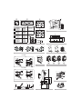
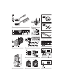
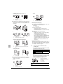
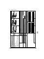
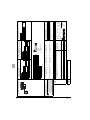
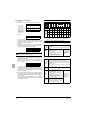
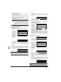
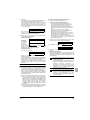
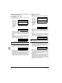
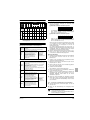
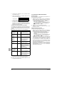
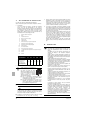
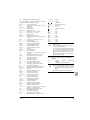
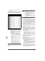
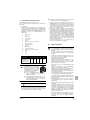
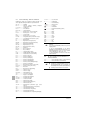
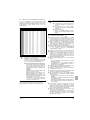
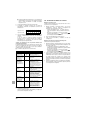
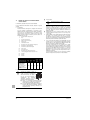
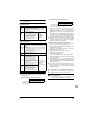
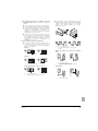
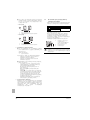
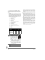
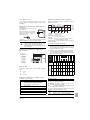
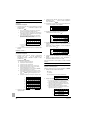
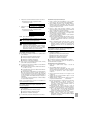
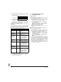
4
Push the BS3 RETURN button and the setting is defined.
5
When the BS3 RETURN button is pushed again, the operation
starts according to the setting.
12.4. Test operation
Do not insert fingers, rods or other objects into the air
inlet or outlet. When the fan is rotating at high speed, it
will cause injury.
Refer to the service manual for more details and for other settings.
Confirmation of the set mode
Do not perform the test operation while working on the
indoor units.
The following items can be confirmed by setting mode 1 (H1P
led is off)
Check the led indication in the field marked
1
When performing the test operation, not only the outdoor
unit, but the connected indoor unit will operate as well.
Working on a indoor unit while performing a test operation
is dangerous.
.
Indication of the present operation state
-
x, normal
w, abnormal
c, under preparation or under test operation
In case refrigerant was added by using the leak detection
function
■
H1P H2P H3P H4P H5P H6P H7P
x
2
x w x
x
x
x
■ Check of the stop valve opening
Indication of COOL/HEAT selection setting
■ Check for wrong wiring
■ Judgement of piping length
1
When set to COOL/HEAT change-over by each individual outdoor
unit circuit (= factory setting).
2
Indication on master unit when COOL/HEAT change-over is
carried out by outdoor system connected in multiple systemcombination.
■
It takes ±3 hours (if the outdoor temperature is low, it takes
±4 hours) to complete the check operation.
3
Indication on slave unit when COOL/HEAT change-over is carried
out by outdoor system connected in multiple system-combination.
■
The system can not perform the judgement of initial refrigerant
state in the following cases:
■ Judgement of initial refrigerant state
■ The outdoor temperature is out of range
(<0°C DB or >43°C DB)
H1P H2P H3P H4P H5P H6P H7P
(a)
1
2
3
x
x
x
x w x x x
x x w x x
x x x w x
x
x
x
■ The indoor temperature is out of range
(<20°C DB or >32°C DB)
■ A forced OFF during the test operation
(a) This setting = factory setting.
3
In this case, after performing the check operation, normal
operation is possible although the abnormality code U3 is
displayed on the indoor remote controller and the refrigerant
leakage detection function can not be used.
Perform the check operation again and complete the judgement
of initial refrigerant state.
Indication of low noise operation state L.N.O.P
-
x standard operation (= factory setting)
w L.N.O.P operation
H1P H2P H3P H4P H5P H6P H7P
x
4
x w x
x
x
x
Indication of power consumption limitation setting DEMAND
-
In the check operation, the following checks and judgements will
be performed:
x standard operation (= factory setting)
w DEMAND operation
In case refrigerant was added without using the leak
detection function (charging in cooling mode)
H1P H2P H3P H4P H5P H6P H7P
x
x w x
Perform the test operation as decribed in the paragraph "Test
operation procedure" on page 26.
x
x
■
x
In the check operation, the following checks and judgement will
be performed:
■ Check of the stop valve opening
■ Check for wrong wiring
■ Judgement of piping length
■
It takes ±30 minutes to complete the check operation.
Check operation procedure
Installation manual
25
1
Close the electric box lid and all front panels except the one on
the side of the electric box.
2
Turn on the power to the outdoor unit and all connected indoor
units. Be sure to turn the power ON at least 6 hours before
operation in order to have power running to the crank case
heater.
3
Make the field setting as needed using the push buttons on the
PCB (A1P) of the outdoor unit. Refer to "Field setting" on
page 23.
U-5~18MX4XPQ
Urban Multi air conditioner
4PW28163-1C