1
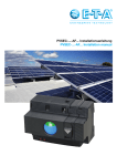
PVREM-...-AF1 Installationsanleitung PVREM-...-AF1 Installation manual Sicherheitshinweise Safety instructions l D ie Installation und Montage dieses Gerätes darf nur von qualifiziertem Fachpersonal durchgeführt werden. l Die Einhaltung der gültigen nationalen Normen, Montagevorschriften und Sicherheitsregeln sind zwingend bei der Installation zu beachten (für USA siehe NFPA 70E). lEine elektrotechnische Funktionsprüfung des PVREM-…-AF1 zur Sicherstellung der Gerätefunktion sollte regelmäßig, z. B. jährlich, durchgeführt werden. Im Falle nationaler oder anwendungsspezifischer Prüfvorschriften sind diese durch den Anlagenbetreiber zu berücksichtigen. lDas Gerät enthält für den Eigenschutz ein internes Fail-Safe-Element, welches bei einer Überlastung anspricht und den Laststromkreis sicher öffnet. l This equipment must be installed and serviced only by qualified electrical personnel. l Apply appropriate personal protective equipment and follow safe electrical work practices. (For US, see NFPA 70E). l Turn off all power supplying this equipment before working on or inside equipment. l Internationally valid standards and installation directions have to be observed during installation without fail. l An electrotechnical functional test to ensure system availability should be carried out regularly on PVREM-...-AF1, e.g. every quarter year. In the event of national or application-specific test directions, these have to be observed by the system operator. l The device holds a fail-safe element for internal protection which trips in the event of overload and reliably interrupts the load circuit. DC-Lasttrennschalter mit Lichtbogenerkennung und Fernantrieb T ype PVREM-…-AF1 – DC-Interrupter with Arc Fault Detection and remote control Type PVREM-T102-...-AF1 (1-polig) Type PVREM-T102-...-AF1 (1-pole version) Type PVREM-T101-...-AF1 (2-polig) Type PVREM-T101-...-AF1 (2-pole version) 2 Anwendung Application Die im PVREM-…-AF1 integrierte Funktion zur Lichtbogenerkennung nach UL 1699B erkennt über einen Sensor serielle und parallele Lichtbögen auf der DC-Seite einer Photovoltaikanlage. The integral Arc Fault Detection function of the PVREM-…-AF1 according to UL 1699B standard detects serial and parallel arcs via a sensor on the DC side of a photo voltaic system. Im Falle eines detektierten Lichtbogens wird ein internes Signal an den Fernantrieb gegeben, der das unmittelbare Öffnen des Lasttrennschalters bewirkt. In the event of a detected arc, an internal signal is forwarded to the remote control causing the interrupter to open imme diately the contacts of the load circuit. Arc Fault Detection is visually indicated with an indicator light. The switching status is indicated locally on the frontface of PVREM-...-AF1 and remotely by means of an auxiliary contact. Die Lichtbogenerkennung erfolgt lokal am PVREM-…-AF1 mittels Leuchtanzeige. Mit frontseitiger, mechanischer Schalt stellungsanzeige und integriertem Si g nal kontakt für die Fernmeldung der Schaltstellung. Zur Erzielung einer möglichst hohen Wahrscheinlichkeit der Lichtbogenerkennung wurde der PVREM-…-AF1 mit Wechsel richtern der führenden Hersteller in verschiedensten Anwendungssituationen ge testet (➡ kontaktieren Sie E-T-A für neueste Informationen zur Kompatibilität mit Wechselrichtern). Aufgrund der stochastischen Natur von Störlichtbögen und unterschiedlichen Lichtbogenarten (parallel, seriell, etc.), ist es nicht möglich eine Erkennungsrate von 100% zu erreichen. Mit der Verwendung der E-T-A Technologie zur Lichtbogenerkennung ist jedoch eine signifikante Erhöhung der Sicherheit von PV-Anlagen möglich. To ensure a high probability of arc fault detection the PVREM-…-AF1 was tested with PV-inverters of major manufacturers in various application situations (➡ contact E-T-A for latest informations on compatibility with PV-inverters). Due to the characteristics of arcs and various types of arcs (parallel, serial,...), a 100% success rate of arc fault detection is impossible. Nevertheless, by using E-T-A technology, it is possible to increase significantly the safety of a PV-system. Furthermore and thanks to its integrated remote control, the PVREM-...- AF1 can be used for functional switching, e.g. for maintenance. Darüber hinaus kann der PVREM-…-AF1 mittels des integrierten Fernantriebs für das betriebsmäßige Ein- und Ausschalten der PV-Anlage eingesetzt werden, z. B. für Wartungszwecke. 3 Übersicht: PVREM-T102-…-AF1 (1-polige Ausführung) 7 1 2 7 1: Eindeutige Schaltstellungsanzeige Schaltstellung Ein: Symbol „I“ und Farbe „rot“ Schaltstellung Aus: Symbol „0“ und Farbe „grün“ 2: Verriegelungselement für Fernantrieb 3: Anzeige „ON“ 4: Anzeige „ARC“ 5: Drucktaste „Reset“ 6: Drucktaste „Test“ 7: Klemmenschrauben Laststromkreis 3 4 5 6 } 8 }9 } 10 11 12 8: Anschlussklemmen externe Versorgungsspannung (DC 24 V, mindestens 1 A) 9: Anschlussklemmen Signalkontakt (1 Wechsler) 10: Anschlussklemmen für externen 3-Stellungsschalter (I-0-II) 11: Befestigungselement für die Montage auf 35 mm Hutschiene 12: Anschlussklemmen Laststromkreis 4 Overview: PVREM-T102-...-AF1 (1-pole version) 7 1 2 7 1: Positive status indication ON: marking “I” and colour “red” OFF: marking “0” and colour “green” 2: Locking element remote control 3: Indicator “ON” 4: Indicator “ARC” 5: Pushbutton “Reset” 6: Pushbutton “Test” 7: Terminal screws load circuit 3 4 5 6 } 8 }9 } 10 11 8: 9: 10: 11: 12: 12 Terminals external supply voltage (DC 24 V, min. 1 A) Terminals auxiliary contact, (1 change-over) Terminals for external three-position switch (I-0-II) Fixing element for mounting on DIN-rail 35 mm Screw terminal load circuit 5 Übersicht: PVREM-T101-…-AF1 (2-polige Ausführung) 7 1 2 7 1: Eindeutige Schaltstellungsanzeige Schaltstellung Ein: Symbol „I“ und Farbe „rot“ Schaltstellung Aus: Symbol „0“ und Farbe „grün“ 2: Verriegelungselement für Fernantrieb 3: Anzeige „ON“ 4: Anzeige „ARC“ 5: Drucktaste „Reset“ 6: Drucktaste „Test“ 7: Klemmenschrauben Laststromkreis 3 4 5 6 } 8 }9 } 10 11 12 8: Anschlussklemmen externe Versorgungsspannung (DC 24 V, mindestens 1 A) 9: Anschlussklemmen Signalkontakt (1 Wechsler) 10: Anschlussklemmen für externen 3-Stellungsschalter (I-0-II) 11: Befestigungselement für die Montage auf 35 mm Hutschiene 12: Anschlussklemmen Laststromkreis 6 Overview: PVREM-T101-...-AF1 (2-pole version) 7 1 2 7 1: Positive status indication ON: marking “I” and colour “red” OFF: marking “0” and colour “green” 2: Locking element remote control 3: Indicator “ON” 4: Indicator “ARC” 5: Pushbutton “Reset” 6: Pushbutton “Test” 7: Terminal screws load circuit 3 4 5 6 } 8 }9 } 10 11 8: 9: 10: 11: 12: 12 Terminals external supply voltage (DC 24 V, min. 1 A) Terminals auxiliary contact, (1 change-over) Terminals for external three-position switch (I-0-II) Fixing element for mounting on DIN-rail 35 mm Screw terminal load circuit 7 Anschluss: PVREM-T102-…-AF1 (1-polige Ausführung) Ungeerdetes System: 1 1 1 M M2 1 2 M AF M 2 + 2 AF - 12 1114 ON C OFF + 24- V12 1114 ON C OFF DC DC 24 V Geerdetes System: M 1 1 2 M 2 M 1 1 2 M 2 Installation lDer PVREM-…-AF1 ist für die Montage auf 35 mm-Gerätetragschienen geeignet. Die Befestigung erfolgt werkzeuglos durch Aufschnappen. lGemäß dem Installationsort ist ggfs. ein Gehäuse zur Erreichung der erforderlichen Schutzart zu verwenden. l Betätigen Sie vor der Verdrahtung das Verriegelungselement für den Fernantrieb nach unten (➡ Schaltstellung „0“). 8 l Verdrahten Sie zuerst den Last stromkreis. Achten Sie dabei auf die korrekte Polarität. l Danach schließen Sie den Signal kontakt und die Versorgungsspannung DC 24 V an. Leiterquerschnitte und Anzugsmomente ➡ siehe Technische Daten. Wiring: PVREM-T102-...-AF1 (1-pole version) Ungrounded system: 1 1 1 M M2 1 2 M AF M 2 + 2 AF - 12 1114 ON C OFF + 24- V12 1114 ON C OFF DC DC 24 V Grounded system: M 1 1 2 M 2 M 1 1 2 M 2 Installation instructions l T he PVREM-…-AF1 can only be mounted on rails with a height of 35 mm (snap-on mounting). l Depending on the installation site an enclosure may be required to achieve the required protection class. lBefore wiring, push the locking element for the remote control (slide switch) down. lFirst wire the load circuit. Then connect the auxiliary contact to the DC 24 V power supply. Cable cross sections and tightening torque ➡ see technical data. 9 Anschluss: PVREM-T101-…-AF1 (2-polige Ausführung) Ungeerdetes System: 1 1 2 3 4 3 M M 2 1 4 + 3 - 12 1114 ON C OFF DC 24 V 1 1 2 3 4 3 Geerdetes System: 2 4 M M 2 M 4 + - 12 1114 ON C OFF DC 24 V 1 2 3 4 1 2 3 4 M M 1 2 3 4 M Installation lDer PVREM-…-AF1 ist für die Montage auf 35 mm-Gerätetragschienen geeignet. Die Befestigung erfolgt werkzeuglos durch Aufschnappen. lGemäß dem Installationsort ist ggfs. ein Gehäuse zur Erreichung der erforderlichen Schutzart zu verwenden. l Betätigen Sie vor der Verdrahtung das Verriegelungselement für den Fernantrieb nach unten (➡ Schaltstellung „0“). 10 l Verdrahten Sie zuerst den Last stromkreis. Achten Sie dabei auf die korrekte Polarität. l Danach schließen Sie den Signal kontakt und die Versorgungsspannung DC 24 V an. Leiterquerschnitte und Anzugsmomente ➡ siehe Technische Daten. Wiring: PVREM-T101-...-AF1 (2-pole version) Ungrounded system: 1 1 2 3 4 M 3 M 2 1 3 4 + - 12 1114 ON C OFF DC 24 V 1 3 2 1 2 3 4 Grounded system: 4 M M 2 M 4 + - 12 1114 ON C OFF DC 24 V 1 2 3 4 1 2 3 4 M M 1 2 3 4 M Installation instructions l The PVREM-…-AF1 can only be mounted on rails with a height of 35 mm (snap-on mounting). l Depending on the installation site an enclosure may be required to achieve the required protection class. lBefore wiring, push the locking element for the remote control (slide switch) down. lFirst wire the load circuit. Then connect the auxiliary contact to the DC 24 V power supply. Cable cross sections and tightening torque ➡ see technical data. 11 Bedienelemente Actuators l Drucktaste „Test“ Durch Drücken der Taste „Test“ führt der PVREM-…-AF1 einen Selbsttest durch. Während des Selbsttests leuchten die Anzeigen „ON“ und „ARC“ gleichzeitig auf. Falls der Selbsttest erfolgreich ist, öffnet der PVREM-…-AF1 die Lastkontakte (➡ Schaltstellung „0“) und nur die Anzeige „ARC“ leuchtet weiterhin. Dauer Selbsttest: 0,1 bis 4 Sekunden. l Pushbutton “Test” After pushing the button “Test” the PVREM-…-AF1 carries out a self test. During the self-test, the indicators “ON” and “ARC” light simultaneously. When the self test is completed successfully, the PVREM-…- AF1 opens the load contacts (➡ position “0”) and only the indicator “ARC” remains lit. Duration self test: 0.1 to 4 seconds. l Drucktaste „Reset“ Durch Drücken der Taste „Reset“ von mindestens 0,5 Sekunden wird der PVREM-…-AF1 nach einer Licht bogenerkennung oder einem erfolgreichen Selbsttest nach Ablauf der Hochlaufphase wieder in den Normalbetrieb zurückgesetzt. Während diesem Vorgang erlöschen die Anzeigen „ON“ und „ARC“. Nach Ablauf der Hochlaufphase leuchtet die Anzeige „ON“ grün. Die Schaltstellung bleibt dabei unverändert. Dauer Hochlaufphase: ca. 4 Sekunden. l Pushbutton „Reset“ By pushing the button “Reset” for at least 0.5 seconds after an arc detection or a successful self-test, the PVREM-…-AF1 will be resetted to normal operation after the end of the start-up phase. During this process the indicators “ON” and “ARC” go out. After the end of the start-up phase the “ON” indicator lights green. The switching position remains unchanged. Duration of the start-up phase approx. 4 seconds. l Verriegelungselement Frontseitiger Schiebeschalter für die mechanische Verriegelung des PVREM-…-AF1 in Schaltstellung „0“ und zur elektrischen Verriegelung des integrierten Fernantriebs. In Schaltstellung „0“ kann der Schiebeschalter mittels Vorhängeschloss (Ø 3 – 4,3 mm) gegen Wiedereinschaltung gesichert werden. 12 l Locking element (Slide switch) Front slide switch for the mechanical locking of the PVREM-...-AF1 in the “0” switching position and for the electrical locking of the integrated remote control. While in the “0” switching position, the slide switch can be mechanically locked against reactivation with a padlock (Ø 3 – 4.3 mm). Anzeigeelemente l Anzeige „ON“ leuchtet grün: D er PVREM-…-AF1 arbeitet im Normalbetrieb. Die Lastkontakte sind geschlossen (➡ Schaltstellung „I“). l Indicator “ON” lights green: The PVREM-…-AF1 is running on normal operation. Load contacts are closed (➡ Switching position “I”). l Anzeige „ARC“ leuchtet rot: Ein Lichtbogen wurde erkannt oder ein erfolgreicher Selbsttest liegt vor. Die Lastkontakte des PVREM-…-AF1 werden geöffnet (➡ Schaltstellung „0“). l Indicator “ARC” lights red: Either an arc has been detected or a successful self-test has been carried out. The load contacts of the PVREM-…-AF1 are opened (➡ Switching position “0”). l A nzeigen „ON“ und „ARC“ leuchten gleichzeitig: Das Gerät führt einen internen Selbsttest durch. Der Selbsttest wird beim Anlegen der DC 24 V Versorgungsspannung oder beim Drücken der Taste „Reset“ durchgeführt. Dauer Selbsttest: 0,1 bis 4 Sekunden. Signalkontakt Indicators l Indicators “ON” and “ARC” light simultaneously: The device carries out an internal self-test. Applying a DC 24 V supply voltage or pressing the “Reset” button triggers the self test. Duration self test: 0.1 to 4 seconds. Auxiliary contact l N enndaten Signalkontakt: 1 Wechsler: DC 24 V, 0,3 A l Rated data of auxiliary contact: 1 change-over contact: DC 24 V, 0.3 A l Betriebszustand EIN: Anschluss 14 und 11 sind geschlossen l Status indication ON Terminals 14 and 11 are closed l B etriebszustand Aus: Anschluss 12 und 11 sind geschlossen l Status indication OFF Terminals 12 and 11 are closed 3-Stellungsschalter l Einschalten: „ON“ und „C“ schließen lAusschalten: „OFF“ und „C“ schließen 3-position switch l Switch on: Close “ON” and “C” lSwitch off: Close “OFF” and “C” ON OFF I 0 II C 12 11 14 13 Funktionsweise l Die Einschaltung des PVREM-…-AF1 erfolgt immer mit Hilfe des integrierten Fernantriebs. ➡ typische Schaltzeit bis Schaltstellung „I“ bei betriebsmäßigen Schalten: 2 Sekunden ➡ typische Schaltzeit bis Schaltstellung „I“ nach Selbsttest oder „Reset“: 4 Sekunden (➡ Dauer Hochlaufphase) l Die Ausschaltung des PVREM-…-AF1 erfolgt immer mit Hilfe des integrierten Fernantriebs. ➡ typische Schaltzeit bis Schaltstellung „0“: < 1 Sekunde l Die Ein- und Ausschaltung des PVREM-…-AF1 wird mittels eines externen 3-Stellungsschalters (I-0-II) gesteuert. - Einschaltung: Durch das Verbinden der Anschlüsse „C“ und „ON“ wird der PVREM-…-AF1 eingeschaltet (➡ Schaltstellung „I“). - Ausschaltung: Durch das Verbinden der Anschlüsse „C“ und „OFF“ wird der PVREM-…-AF1 ausgeschaltet (➡ Schaltstellung „0“). lNach der Ausschaltung in Folge eines erfolgreichen Selbsttestes muss zur Wiedereinschaltung des PVREM-…-AF1 und Aktivierung der Funktion Licht bogenerkennung, die Taste „Reset“ gedrückt werden. 14 Operation l The PVREM-…-AF1 is always switched on by means of the integrated remote control. ➡ typical time till reaching the switching position “I” during operational switching: 2 seconds ➡ typical time till reaching the switching position “I” after the self-test or “Reset”: 4 seconds (➡ Duration of start-up phase) lThe PVREM-…-AF1 is always switched off by the assistance of the integrated remote control. ➡ typical tripping time till switching position “0”: < 1 second l The PVREM-...-AF1 is switched on and off via an external three-position switch (I-0-II). - Switching on: By connecting the terminals “C” and “ON” the PVREM...-AF1 is switched on (➡ switching position „I“). - Switching off: By connecting the terminals “C” and “OFF” the PVREM...-AF1 is switched off (➡ switching position „0“). lAfter a switching off due to a successful self-test, the pushbutton “Reset” has to be pressed in order to switch on again the PVREM-...-AF1 including the activation of the Arc Fault Detection. Software l Die für die Funktion Lichtbogen erkennung notwendige Software gemäß UL 1998 ist im PVREM-…-AF1 fest gespeichert. lVom Installateur oder Betreiber ist keine Programmierung oder Parametrierung notwendig. Software l The software used for the function Arc Fault Detection according UL 1998 is permanently stored in the PVREM-…-AF1. l Neither programming nor parameter selection are required from the installer or operator of the PVREM-…-AF1. 15 Technische Daten Polzahl: PVREM-T102-…-AF1: 1-polig PVREM-T101-…-AF1: 2-polig Normen: PVREM-T10x-…-AF1: Lichtbogendetektor (PV DC AFD type 1) nach UL 1699B, UL File E356917, Lasttrennschalter geprüft nach IEC/EN 60947-3 Lastkreis: Bemessungsbetriebsspannung: DC 1000 V Bemessungsstrom: 30 A Externe Versorgungsspannung: DC 24 V, mindestens 1 A Umgebungstemperatur: -30 °C bis +60 °C Schutzart: (Anschlussbereich) IP20 nach EN 60529 NEMA 1 Abmessungen (B x H x T): 121 x 108,5 x 84,5 mm Anschluss Laststromkreis: Anschlussart: Anzugsmoment: Leitermaterial: Leiterquerschnitt: Abisolierlänge: Schlitzschraube M4 1,2 Nm Kupfer starr und mehrdrähtig: 0,5 – 16 mm² flexibel mit Aderendhülse 0,5 – 10 mm² flexibel mit TWIN-Aderendhülse: 0,5 – 6 mm² AWG 20 – 6 10 mm Anschluss Hilfsstromkreis (Signalkontakt, DC 24 V Versorgungsspannung) Anschlussart: Leitermaterial: Leiterquerschnitt: Abisolierlänge: PUSH-IN (schraublos) Kupfer starr H05(07) V-U mehrdrähtig H07 V-R flexibel H05(07) V-K flexibel mit Aderendhülse: 0,25 – 1,5 mm² Aderendhülse mit Kunststoffkragen: 0,25 – 0,75 mm² AWG 24 – 16 8 mm Weitere Informationen finden Sie in unserem Hauptkatalog und auf unserer Internetseite www.e-t-a.de 16 Technical data Number of poles: PVREM-T102-...-AF1: 1-pole PVREM-T101-...-AF1: 2-pole Standards: PVREM-T10x-...-AF1:PV DC Arc Fault Detector (AFD) type 1 according UL 1699B, UL File E356917 Integral Interrupting Device (ID) according IEC/EN 60947-3 Load circuit: Rated voltage: Rated current: DC 1000 V 30 A External power supply: DC 24 V, at least 1 A Ambient temperature: -30 °C to +60 °C Degree of protection: (Terminal area) IP20 to EN 60529 NEMA 1 Dimensions (w x h x d): 121 x 108.5 x 84.5 mm Connection load circuit: Terminal design: Tightening torque: Conductor material: Cable cross section: Wire stripping length: M4 slotted screw 1.2 Nm Copper rigid and multi-stranded: flexible with ferrule flexible with TWIN-ferrule: AWG 20 – 6 10 mm Connection of auxiliary circuits (auxiliary contact, DC 24 V power supply) Terminal design: PUSH-IN (screwless) Conductor material: Copper Cable cross section: rigid H05(07) V-U multi-stranded H07 V-R flexible H05(07) V-K flexible with ferrule: ferrule with plastic collar: AWG 24 – 16 Wire stripping length: 8 mm 0.5 – 16 mm² 0.5 – 10 mm² 0.5 – 6 mm² 0.25 – 1.5 mm² 0.25 – 0.75 mm² For further technical data please refer to our catalogue or visit our website www.e-t-a.de/e 17 DE: Download Installationsanleitung www.e-t-a.de/PVREM-AF1/M_de EN: Download installation manual www.e-t-a.de/PVREM-AF1/M_en FR: Download manuel de l´utilisateur www.e-t-a.fr/PVREM-AF1/M_fr IT: Download manuale d´uso www.e-t-a.it/PVREM-AF1/M_it ES: Download manual de instrucciones www.e-t-a.es/PVREM-AF1/M_es ダウンロード インストールマニュアル www.e-t-a.co.jp/PVREM-AF1/M_jp 18 Allgemeiner Sicherheitshinweis Eine Nichtbeachtung der Montage- und Bedienungsanleitung kann zu erheblichen Schäden am Gerät und an der Anlage führen. E-T-A übernimmt gegenüber Kunden oder Dritten keine Haftung, Gewährleistung oder Garantie für Mängel oder Schäden, die durch fehlerhaften Einbau oder unsachgemäße Handhabung unter Nichtbeachtung der Montage- und Bedienungsanleitung verursacht sind. Installationsanleitung für DC-Lasttrennschalter PVREM-AF1 Bestell-Nr. Y 31 11 50 01 Index: a Ausgabe 07/2013 E-T-A Elektrotechnische Apparate GmbH Alle Rechte vorbehalten General Caution Please follow these instructions carefully. Failure to comply, or misuse of this equipment, could result in serious damage both to the equipment itself and to the installation. E-T-A is unable to accept responsibility for customer or third party liability, warranty claims or damage caused by incorrect installation or improper handling resulting form non-observance of these instructions. Installation manual for DC-Interrupter PVREM-AF1 Ref. number Y 31 11 50 01 Index: a Issue 07/2013 E-T-A Elektrotechnische Apparate GmbH All rights reserved 19 M_PVREM_AF1_d_e_310713A E-T-A Elektrotechnische Apparate GmbH Industriestraße 2-8 . D-90518 ALTDORF GERMANY Phone 09187 10-0 . Fax 09187 10-397 E-Mail: [email protected] . www.e-t-a.de