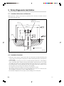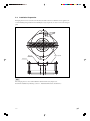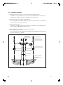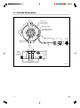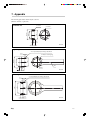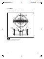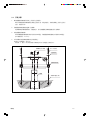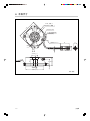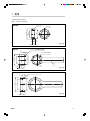
1
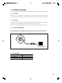
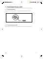
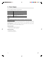
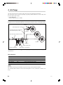
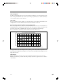
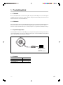
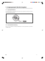
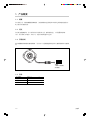
Rotary Magnescale / Dreh-Magnescale / 磁栅旋转编码器
RU77
Read all the instructions in the manual carefully before use and strictly follow them.
Keep the manual for future references.
Lesen Sie die ganze Anleitung vor dem Betrieb aufmerksam durch und folgen Sie beim
Betrieb des Geräts den Anweisungen.
Bewahren Sie diese Anbringungsanleitung zum späteren Nachlesen griffbereit auf.
感谢您惠购本产品。
使用之前请务必认真阅读本手册,并且严格按照手册中的规定操作。
将此手册留作以后的参考。
Installation Manual / Anbringungsanleitung / 安装说明书
RU77
Safety Precautions
Sony Manufacturing Systems Corporation products are designed in full consideration of safety.
However, improper handling during operation or installation is dangerous and may lead to fire,
electric shock or other accidents resulting in serious injury or death. In addition, these actions
may also worsen machine performance.
Therefore, be sure to observe the following safety precautions in order to prevent these types of
accidents, and to read these “Safety Precautions” before operating, installing, maintaining, inspecting, repairing or otherwise working on this unit.
Warning indication meanings
The following indications are used throughout this manual, and their contents should be understood before reading the text.
Warning
Failure to observe these precautions may lead to fire, electric shock or other accidents resulting
in serious injury or death.
Caution
Failure to observe these precautions may lead to electric shock or other accidents resulting in
injury or damage to surrounding objects.
Warning
. Do not use this unit with voltages other than the specified supply voltages as this may
result in fire or electric shock.
. Do not perform installation work with wet hands as this may result in electric shock.
. Do not disassemble or modify the unit as this may result in injury or damage the
internal circuits.
RU77
(E) (1)
Caution
. Be sure to check the machine and device conditions to ensure work safety before
working on the machine.
. Be sure to cut off the power supply and other sources of drive power before working
on the machine. Failure to do so may result in fire or accidents.
. When turning on the power supply or other sources of drive power to operate the
machine, take care not to catch your fingers in peripheral machines and devices.
General Precautions
When using Sony Manufacturing Systems Corporation products, observe the following general precautions along
with those given specifically in this manual to ensure proper use of the products.
. Before and during operations, be sure to check that our products function properly.
. Provide adequate safety measures to prevent damages in case our products should develop malfunctions.
. Use outside indicated specifications or purposes and modification of our products will void any warranty of the
functions and performance as specified of our products.
. When using our products in combination with other equipment, the functions and performance as noted in this
manual may not be attained, depending upon operating environmental conditions. Make full study of the compatibility in advance.
(2) (E)
RU77
[For U.S.A. and Canada]
THIS CLASS A DIGITAL DEVICE COMPLIES WITH
PART15 OF THE FCC RULES AND THE CANADIAN
ICES-003. OPERATION IS SUBJECT TO THE
FOLLOWING TWO CONDITIONS.
(1) THIS DEVICE MAY NOT CAUSE HARMFUL
INTERFERENCE, AND
(2) T H I S D E V I C E M U S T A C C E P T A N Y
INTERFERENCE RECEIVED, INCLUDING
INTERFERENCE THAT MAY CAUSE
UNDERSIGNED OPERATION.
CET APPAREIL NUMÉRIQUE DE LA CLASSE A
EST CONFORME À LA NORME NMB-003 DU
CANADA.
RU77
(E) (3)
(4) (E)
RU77
Contents
1. Product Overview .............................................................. 1
1-1.
1-2.
1-3.
1-4.
Overview ......................................................................................................... 1
Features ........................................................................................................... 1
System Configuration ...................................................................................... 1
Accessories ...................................................................................................... 1
2. Output Signal (Serial output) ........................................... 2
2-1.
2-2.
Signal Specifications ....................................................................................... 2
Communication Circuit Side ........................................................................... 2
3. Power Supply ..................................................................... 3
4. Air Purge ............................................................................ 4
5. Rotary Magnescale Installation ....................................... 6
5-1.
5-2.
5-3.
5-4.
Installation Dimensions and Tolerance ........................................................... 6
Installation Precaution ..................................................................................... 6
Installation Preparation ................................................................................... 7
Installation Procedure ...................................................................................... 8
6. Outside Dimensions ......................................................... 9
7. Appendix .......................................................................... 10
RU77
(E) i
ii (E)
RU77
1. Product Overview
1-1. Overview
This product is a compact, high-accuracy rotary magnescale that outputs position signals for machine tools
and other equipment requiring high-accuracy positioning. This is an absolute serial communication model.
1-2. Features
In addition to being a magnetic detection system, this product has a unit shape that enables easy installation
and provides superior environmental resistance from condensation and other effects.
Because of its extremely slim design (max. 42 mm), less space is taken up when installing in equipment.
1-3. System Configuration
RU77 has an interpolation circuit built into the rotary magnescale and is a serial communication model,
compliant with absolute serial communication specifications, that enables connection to a controller.
Number of divisions:
2 to the nth power divisions
(Serial communication)
1-4. Accessories
Hex. socket-head cap screws
M4 x 16
Flat washers
for M4
4
4
Installation Manual
1
Accuracy chart
1
RU77
(E) 1
2. Output Signal (Serial output)
2-1. Signal Specifications
RU77 performs data communication with a controller using absolute serial communication protocol.
2-2. Communication Circuit Side
When connecting to a controller, be sure to follow the connection procedure of the controller manufacturer.
2 (E)
RU77
3. Power Supply
Use a power supply that satisfies the specifications below.
Use of a power supply with a short-circuit protection device is recommended.
Item
Power supply specifications
Supply voltage
DC 4.75 - 5.25 V
Consumption current
200 mA or less (for each axis)
Inrush current
2 A or less
(When the power supply rise time is 10 ms.)
Ripple voltage
50 mVp-p or less
n
When using the rotary magnescale with an external power supply instead of with a
controller power supply
The rotary magnescale begins functioning normally approximatelly 0.3 seconds after the power is turned on.
Signal might come out momentarily when the power is turned on or off, and this signal can cause the entire
system to malfunction.
To prevent this, be sure to follow the proper power-on and power-off procedures. Also, use the procedures
below to turn the power off and on again if a malfunction occurs.
Power-on procedure
1. Turn on the power for the rotary magnescale.
2. Turn on the power for the receiving device.
Power-off procedure
1. Turn off the receiving device.
2. Turn off the rotary magnescale.
RU77
(E) 3
4. Air Purge
Air can be injected into the scale unit to reduce the effects of the environments shown below.
The actual effects, however, will vary depending on operating conditions. Therefore, be sure to fully check
the effects before using air purge.
. Use in dusty area
. Use in locations close to coolants
Air Tube Route and Device Configuration
Prepare the devices as shown in the figure below, and air is injected into the scale by connecting the air tubes.
+B M5 x 6
Tube bending radius R: 15 mm or more
Polyurethane tube with outer diameter of
6 mm and inner diameter of 4 mm
Air nipple
Nylon tube with outer diameter of 8 mm
Air pressure source
Scale unit
Distributors
Pressure reducing valve
Air filter (5 um filtration)
Mist separator (0.3 um filtration)
The customer must obtain the air supply unit and input/output air tubes (IN side: φ8, OUT side: φ6, both
outer diameter).
Main components
Manufacturer
Model
Name
Quantity
SMC Corporation
AF3000-02C
Air filter: 5 um
1
SMC Corporation
AFM3000-02C
Mist separator: 0.3 um
1
SMC Corporation
AR3000-02G-1
Regulator with 200 kPa pressure gauge
1
SMC Corporation
Y30L
Spacer assembly with L-type bracket
1
SMC Corporation
KQ2S06-M5
Air nipple
1
n
The air filter and mist separator should incorporate a float-type auto drain (NC) mechanism.
Use a drain tube with a diameter of at least 4 mm and length of 5 m or less. Set the tubes so that there is no
rising.
4 (E)
RU77
Tube Layout Notes
Tube arrangement
Use tubes with a bending radius of at least 15 mm and make sure that there are no sharp bends. Also, if the
tubes are laid parallel within the ducts for the electrical wiring or hydraulic tubes, be careful that the tubes
are not crushed by the movement of the ducts.
Tube length
To inject air simultaneously into multiple scales, make the tubes the same length from the distributor of the
air supply unit to each scale so that the injection air pressure is uniform for each scale.
Pressure setting of pressure reducing valve
Pressure setting and tube length for pressure reducing valve
If the air injection pressure for each scale is around 20 ±10 kPa, the air in the scale can be maintained at a
low humidity. However, setting the air injection pressure only via the pressure reducing valve will not result
in an air injection pressure of 20 ±10 kPa due to pressure losses stemming from the tube length.
Refer to graph below to determine the pressure setting of the pressure reducing valve.
Pressure reduction setting and tube length
(kPa)
40
35
30
25
20
15
10
5
0
0
1
2
3
4
5
6
7
8
9
10
(m)
Length of polyurethane tube with outer diameter of 6 mm and inner diameter of 4 mm
This graph illustrates the relationship between the regulator pressure setting and tube length when the air
injection pressure is 20 kPa. The tube length here is considered to be the length from the distributor of the air
supply unit to the scale.
Tube flushing
Flush the tube from the air pressure source to the air supply unit connectors and each scale connector.
Flushing cleans the tubes, prevents the embedding of foreign objects in the equipment, and is also useful to
check the tubes.
RU77
(E) 5
5. Rotary Magnescale Installation
5-1. Installation Dimensions and Tolerance
Make preparations so that the rotary magnescale installation surface dimensions and tolerance have the
values shown in the figure below.
Installation nut
(Obtained by the customer.)
(M20 x 1)
ø100
ø85H7 ( +0.035
)
0
(12)
ø0.1 A
3±0.1
ø20g6
( ––0.007
0.020 )
0.01 A
0.1 A
0.02 A
5
32 –10
4 x M4
A
A : Bearing rotation center
ø29 +–14
Unit: mm
5-2. Installation Precaution
. If the surface of the rotary side or stationary side where the rotary magnescale will be installed has paint
or other coating, remove the paint or coating in order to obtain conductivity between the rotary magnescale
and the machine.
. Before installing the rotary magnescale, be sure to check that the dimensional tolerance of the installation
surface and machine shaft are within the standards. If the installation dimensional tolerance is not within
the standards, the required accuracy will not be obtained, and the rotary magnescale can even be damaged.
. In environments where coolant can splash directly on the rotary magnescale, be sure to mount a cover on
the rotary magnescale to protect the rotary magnescale from splashing.
. The installation nut and other installation tools must be obtained by the customer.
. The absolute position becomes 0 at the reference point mark ±2 degrees. Be sure to check its location
when securing the scale shaft. (See section 6, “Outside Dimensions.”)
. In its standard configuration, the rotary magnescale has an M5 tap hole for air injection.
6 (E)
RU77
5-3. Installation Preparation
Transport plate is used to secure the scale unit and scale shaft so that excess vibrations are not applied to the
scale shaft during transportation. Before installing the rotary magnescale, be sure to remove the transport
plate.
+B 3 x 5
Transport plate
+B 6 x 35
n
The transport plate does not set the installation standard for the rotary magnescale.
Perform the installation by following section 5-1, “Installation Dimensions and Tolerance.”
RU77
(E) 7
5-4. Installation Procedure
1. Check that there is no dust or scratches on the rotary magnescale installation surface.
Check that there are no indentations, rust, or scratches on the machine shaft where the rotary magnescale
will be installed. Completely wipe off any dust and dirt on the machine shaft.
2. Insert the rotary magnescale gently into the machine shaft.
The machine shaft and scale shaft are designed for a precise fit, and so do not try to force insertion of
the rotary magnescale into the machine shaft.
3. Secure the rotary magnescale.
Use M4 screws to install from the rotary magnescale top, and use M6 screws to install from the rotary
magnescale bottom. (M4 tightening torque: 2.5 N.m)
4. Use the installation nut to secure the scale shaft to the machine shaft.
(M20 x 1 tightening torque: 20 N.m)
The securing operation can be performed more smoothly by using a tightening wrench and fastening
wrench as shown in the “7. Appendix.”
Installation nut
(obtain separately)
M4 x 16 (included)
Flat washers (included)
Rotary magnescale unit
Machine shaft
M4 tap for installation
(4 locations)
8 (E)
RU77
6. Outside Dimensions
4 x M3, depth: 5
ø100
0
ø11
s
92
4 x ø3.3 ±0.1, depth: 7
Air injection hole (M5)
4 x mounting hole for M4
(when installing from top)
ø35
Cable length 1000 +100
0
44
17
ø5.6
ø18
Reference mark
10°
30
40
42
3
ø20H6 ( +0.013
)
–0
ø85f7 ( –0.036
–0.071 )
±0.05
10
4 x M6
(when
installing
from bottom)
33±0.1
ø30H6 ( +0.013
)
–0
Unit: mm
RU77
(E) 9
7. Appendix
The following parts must be obtained by the customer.
(Material: SUS303 or equivalent)
Installation nut
4 x ø2.8±0.1
ø25±0.1
M20 x 1
ø29.6±0.1
2 x C0.5
4±1
8
Unit: mm
Tightening wrench
4 x ø2.5 parallel pin press fitting or attachment
3.5
±0.2
ø25±0.1
ø20.4±0.1
ø29.6±0.2
4 x M3 (for securing ring)
Arm
Ring
(6)
8
Unit: mm
Fastening wrench
4 x ø3 parallel pin press fitting or attachment
ø35±0.1
ø30 +– 00.2
ø40±0.2
5±0.2
(6)
10 (E)
Unit: mm
RU77
Sicherheitsmaßnahmen
Bei dem Entwurf von Sony Manufacturing Systems Corporation Produkten wird größter Wert
auf die Sicherheit gelegt. Unsachgemäße Handhabung während des Betriebs oder der Installation ist jedoch gefährlich und kann zu Feuer, elektrischen Schlägen oder anderen Unfällen
führen, die schwere Verletzungen oder Tod zur Folge haben können. Darüber hinaus kann
falsche Anwendung die Leistung der Maschine verschlechtern.
Beachten Sie daher unbedingt die besonders hervorgehobenen Sicherheitshinweise in dieser
Bedienungsanleitung, um derartige Unfälle zu verhüten, und lesen Sie die folgenden
Sicherheitsmaßnahmen vor der Inbetriebnahme, Installation, Wartung, Inspektion oder Reparatur
dieses Gerätes oder der Durchführung anderer Arbeiten durch.
Bedeutung der Warnhinweise
Bei der Durchsicht dieses Handbuchs werden Sie auf die folgenden Hinweise und Symbole
stoßen. Machen Sie sich mit ihrer Bedeutung vertraut, bevor Sie den Text lesen.
Warnung
Eine Missachtung dieser Hinweise kann zu Feuer, elektrischen Schlägen oder anderen Unfällen
führen, die schwere Verletzungen oder Tod zur Folge haben können.
Vorsicht
Eine Missachtung dieser Hinweise kann zu elektrischen Schlägen oder anderen Unfällen führen,
die Verletzungen oder Sachbeschädigung der umliegenden Objekte zur Folge haben können.
Warnung
. Betreiben Sie dieses Gerät nur mit der vorgeschriebenen Versorgungsspannung, da
anderenfalls die Gefahr von Feuer oder elektrischen Schlägen besteht.
. Führen Sie Installationsarbeiten nicht mit nassen Händen aus, da hierbei die Gefahr
elektrischer Schläge besonders groß ist.
. Unterlassen Sie jeden Versuch, das Gerät zu zerlegen oder umzubauen, da dies zu
Verletzungen oder Beschädigung der internen Schaltungen führen kann.
RU77
(G) (1)
Vorsicht
. Überprüfen Sie vor Arbeitsbeginn unbedingt den Zustand von Maschine und
Vorrichtungen, um die Arbeitssicherheit zu gewährleisten.
. Schalten Sie vor Arbeiten an der Maschine unbedingt die Stromzufuhr und andere
Antriebsstromquellen aus. Anderenfalls besteht Brand- oder Unfallgefahr.
. Achten Sie beim Einschalten der Stromversorgung usw. zum Betrieb der Maschine
darauf, dass Sie sich nicht die Finger in peripheren Maschinen und Vorrichtungen
klemmen.
Allgemeine Vorsichtsmaßregeln
Beachten Sie bei Verwendung unserer Produkte die folgenden allgemeinen Vorsichtsmaßregeln neben den in
diesem Handbuch speziell vermerkten Hinweisen, um korrekten Gebrauch der Produkte zu gewährleisten.
. Vergewissern Sie sich vor und während des Betriebs, dass das Produkt einwandfrei funktioniert.
. Treffen Sie angemessene Sicherheitsmaßnahmen, um im Falle von Funktionsstörungen Schäden zu vermeiden.
. Der Einsatz außerhalb der angegebenen Spezifikationen oder Zwecke und die Modifikation unserer Produkte
haben den Verfall der Garantie auf die angegebenen Funktionen und Leistungen unserer Produkte zur Folge.
. Bei Verwendung unserer Produkte in Verbindung mit anderen Geräten werden je nach den
Betriebsumgebungsbedingungen die in dieser Anleitung angegebenen Funktionen und Leistungen
möglicherweise nicht erzielt. Daher sollte die Kompatibilität vorher gründlich überprüft werden.
(2) (G)
RU77
[For U.S.A. and Canada]
THIS CLASS A DIGITAL DEVICE COMPLIES WITH
PART15 OF THE FCC RULES AND THE CANADIAN
ICES-003. OPERATION IS SUBJECT TO THE
FOLLOWING TWO CONDITIONS.
(1) THIS DEVICE MAY NOT CAUSE HARMFUL
INTERFERENCE, AND
(2) T H I S D E V I C E M U S T A C C E P T A N Y
INTERFERENCE RECEIVED, INCLUDING
INTERFERENCE THAT MAY CAUSE
UNDERSIGNED OPERATION.
CET APPAREIL NUMÉRIQUE DE LA CLASSE A
EST CONFORME À LA NORME NMB-003 DU
CANADA.
RU77
(G) (3)
(4) (G)
RU77
Inhalt
1. Produktüberblick ............................................................... 1
1-1.
1-2.
1-3.
1-4.
Überblick ......................................................................................................... 1
Merkmale ........................................................................................................ 1
Systemkonfiguration ....................................................................................... 1
Zubehör ........................................................................................................... 1
2. Ausgangssignal (Serielle Ausgabe) ................................ 2
2-1.
2-2.
Signalspezifikationen ...................................................................................... 2
Kommunikationsschaltung .............................................................................. 2
3. Stromversorgung .............................................................. 3
4. Frischluftspülung .............................................................. 4
5. Installation des Dreh-Magnescales ................................. 6
5-1.
5-2.
5-3.
5-4.
Installationsmaße und Maßtoleranzen ............................................................. 6
Vorsichtshinweise zur Installation ................................................................... 6
Installationsvorbereitung ................................................................................. 7
Installationsverfahren ...................................................................................... 8
6. Außenabmessungen ......................................................... 9
7. Anhang ............................................................................. 10
RU77
(G) i
ii (G)
RU77
1. Produktüberblick
1-1. Überblick
Bei diesem Produkt handelt es sich um ein kompakten, hochgenaues Dreh-Magnescale, das Positionssignale
für Werkzeugmaschinen und andere Geräte ausgibt, die hochgenaue Positionierung erfordern. Dies ist ein
Modell mit absoluter serieller Kommunikation.
1-2. Merkmale
Neben der Eigenschaft als magnetisches Erkennungssystem besitzt dieses Produkt eine installationsfreundliche
Einheitsform und bietet hervorragende Umweltbeständigkeit gegen Kondensation und andere Effekte.
Dank seiner äußerst schlanken Form (max. 42 mm) beansprucht es weniger Platz beim Einbau in Anlagen.
1-3. Systemkonfiguration
Das Modell RU77 besitzt eine ins Dreh-Magnescale eingebaute Interpolationsschaltung und bedient sich
serieller Kommunikation, die mit den Spezifikationen für absolute serielle Kommunikation kompatibel ist
und den Anschluss mit einem Steuergerät ermöglicht.
Anzahl der Teilungen:
Teilungen von 2 bis zur
n-ten Potenz
(serielle Kommunikation)
1-4. Zubehör
Innensechskantschraube
M4 x 16
4
Unterlegscheiben
für M4
4
Anbringungsanleitung
1
Genauigkeitstabelle
1
RU77
(G) 1
2. Ausgangssignal (Serielle Ausgabe)
2-1. Signalspezifikationen
Die Datenkommunikation des Modells RU77 mit einem Steuergerät erfolgt unter Verwendung eines absoluten
seriellen Kommunikationsprotokolls.
2-2. Kommunikationsschaltung
Befolgen Sie beim Anschluss an ein Steuergerät unbedingt das vom Steuergerätehersteller vorgeschriebene
Anschlussverfahren.
2 (G)
RU77
3. Stromversorgung
Verwenden Sie für das Dreh-Magnescale eine Stromquelle, die den folgenden Spezifikationen entspricht.
Die Verwendung einer Stromversorgung mit einer Kurzschluss-Schutzvorrichtung wird empfohlen.
Gegenstand
Stromversorgungsspezifikationen
Versorgungsspannung
DC 4,75 - 5,25 V
Stromverbrauch
200 mA oder weniger (für jede Achse)
Einschaltstromstoß
2 A oder weniger
(Wenn die Stromversorgungs-Anstiegszeit 10 ms beträgt.)
Welligkeitsspannung
50 mVs-s oder weniger
Hinweis
Bei Verwendung des Dreh-Magnescales mit externer Stromversorgung anstelle der
Steuergeräte-Stromversorgung
Das Dreh-Magnescale beginnt etwa 0,3 Sekunden nach dem Einschalten der Stromversorgung normal zu
arbeiten.
Beim Ein- oder Ausschalten kann es vorkommen, dass kurzzeitig ein Signal ausgegeben wird, das eine
Funktionsstörung des ganzen Systems verursachen kann.
Um dies zu verhüten, sollten Sie das korrekte Ein- und Ausschaltverfahren befolgen. Schalten Sie außerdem
die Stromversorgung im Störungsfall nach den folgenden Verfahren aus und wieder ein.
Einschaltverfahren
1. Schalten Sie das Dreh-Magnescale ein.
2. Schalten Sie das Empfangsgerät ein.
Ausschaltverfahren
1. Schalten Sie das Empfangsgerät aus.
2. Schalten Sie das Dreh-Magnescale aus.
RU77
(G) 3
4. Frischluftspülung
Um die Auswirkungen der unten aufgeführten Umgebungen zu reduzieren, kann Luft in den Maßstab
eingeblasen werden.
Die tatsächlichen Effekte hängen jedoch von den Betriebsbedingungen ab. Daher sollten Sie die Effekte
gründlich überprüfen, bevor Sie Frischluftspülung verwenden.
. Einsatz in staubiger Umgebung
. Einsatz in Orte in der Nähe von Kühlmittel
Luftschlauchführung und Gerätekonfiguration
Wenn Sie die Geräte so anordnen, wie in der nachstehenden Abbildung dargestellt, kann Luft durch
Anschließen von Luftschläuchen in den Maßstab eingeblasen werden.
+B M5 x 6
Schlauchbiegeradius R:
15 mm oder mehr
Polyurethanschlauch mit 6 mm
Außendurchmesser und 4 mm
Innendurchmesser
Schlauchnippel
Nylonschlauch mit 8 mm
Außendurchmesser
Druckluftquelle
Maßstab
Verteiler
Druckminderungsventil
Luftfilter
(5 um Filterfeinheit)
Tropfenabscheider (0,3 um Filterfeinheit)
Der Kunde muss die Luftversorgungseinheit und die Luftschläuche für Eingang/Ausgang beschaffen
(IN-Seite: φ8, OUT-Seite: φ6, beide Außendurchmesser).
Hauptkomponenten
Hersteller
Modell
Bezeichnung
Menge
SMC Corporation
AF3000-02C
Luftfilter: 5 um
1
SMC Corporation
AFM3000-02C
Tropfenabscheider: 0,3 um
1
SMC Corporation
AR3000-02G-1
Regler mit 200-kPa-Druckmesser
1
SMC Corporation
Y30L
Abstandshalterzubehör mit L-Halter
1
SMC Corporation
KQ2S06-M5
Schlauchnippel
1
Hinweis
Luftfilter und Tropfenabscheider sollten einen automatischen Ablassmechanismus (NC) in
Schwimmerausführung enthalten.
Verwenden Sie einen Ablassschlauch mit einem Durchmesser von mindestens 4 mm und einer Länge von
maximal 5 m. Bringen Sie die Schläuche so an, dass keine Anstauung entsteht.
4 (G)
RU77
Hinweise zum Schlauchlayout
Schlauchanordnung
Verwenden Sie Schläuche mit einem Biegeradius von mindestens 15 mm, und vergewissern Sie sich, dass
keine scharfen Biegungen entstehen. Wenn Sie die Schläuche parallel innerhalb der Durchführungen für die
Elektrokabel oder Hydraulikschläuche verlegen, müssen Sie darauf achten, dass die Schläuche nicht durch
die Bewegung der Durchführungen eingedrückt werden.
Schlauchlänge
Um Luft gleichzeitig in mehrere Maßstäbe einzublasen, sollten die Schläuche die gleiche Länge vom Verteiler
der Luftversorgungseinheit bis zum jeweiligen Maßstab haben, so dass der Einblas-Luftdruck für jeden
Maßstab gleich ist.
Druckeinstellung des Druckminderungsventils
Druckeinstellung und Schlauchlänge für Druckminderungsventil
Wenn der Einblasdruck für jeden Maßstab etwa 20 ±10 kPa beträgt, kann die Luftfeuchtigkeit im Maßstab
niedrig gehalten werden. Wird jedoch der Lufteinblasdruck nur mit dem Druckminderungsventil eingestellt,
erhält man wegen der durch die Schlauchlänge bedingten Druckverluste keinen Lufteinblasdruck von
20 ±10 kPa. Nehmen Sie das nachstehende Diagramm zu Hilfe, um die Druckeinstellung des
Druckminderungsventils zu bestimmen.
Druckminderungseinstellung und Schlauchlänge
(kPa)
40
35
30
25
20
15
10
5
0
0
1
2
3
4
5
6
7
8
9
10
(m)
Länge des Polyurethanschlauchs mit 6 mm Außendurchmesser
und 4 mm Innendurchmesser
Diese Grafik veranschaulicht die Beziehung zwischen der Druckeinstellung des Reglers und der Schlauchlänge
bei einem Lufteinblasdruck von 20 kPa. Als Schlauchlänge wird hier die Länge vom Verteiler der
Luftversorgungseinheit bis zum Maßstab angenommen.
Schlauchspülung
Spülen Sie die Schläuche von der Druckluftquelle zu den Anschlüssen der Luftversorgungseinheit und jedem
Maßstabanschluss aus.
Auf diese Weise können Sie die Schläuche reinigen, das Eindringen von Fremdkörpern in die Anlage verhüten
und außerdem eine Prüfung der Schläuche durchführen.
RU77
(G) 5
5. Installation des Dreh-Magnescales
5-1. Installationsmaße und Maßtoleranzen
Treffen Sie Vorbereitungen, damit die Abmessungen und Maßtoleranzen der Dreh-MagnescalesInstallationsfläche den in der nachstehenden Abbildung gezeigten Werten entsprechen.
Installationsmutter
(vom Kunden zu besorgen)
(M20 x 1)
ø100
ø85H7 ( +0,035
)
0
(12)
ø0,1 A
3±0,1
ø20g6
( ––0,007
0,020 )
0,01 A
0,1 A
0,02 A
5
32 –10
4 x M4
A
A : Lagerdrehachse
ø29 +–14
Einheit: mm
5-2. Vorsichtshinweise zur Installation
. Falls die Oberfläche des rotierenden oder stationären Teils der Installationsfläche des Dreh-Magnescales
lackiert ist oder einen anderen Überzug aufweist, ist der Lack oder Überzug zu entfernen, um eine gute
Leitfähigkeit zwischen dem Dreh-Magnescale und der Maschine zu erhalten.
. Vergewissern Sie sich vor der Installation des Dreh-Magnescales, dass die Maßtoleranz der
Installationsfläche und der Maschinenwelle innerhalb der Normen liegt. Liegt die Maßtoleranz der
Installationsfläche nicht innerhalb der Normen, kann die erforderliche Genauigkeit nicht erzielt werden,
was möglicherweise zu einer Beschädigung des Dreh-Magnescales führen kann.
. Bringen Sie in Umgebungen, wo Kühlmittel direkt auf das Dreh-Magnescale spritzen kann, eine Abdeckung
am Dreh-Magnescale an, um ihn vor Spritzern zu schützen.
. Die Installationsmutter und andere Installationswerkzeuge sind vom Kunden zu beschaffen.
. Die Absolutposition wird 0 an der Bezugspunktmarkierung ±2 Grad. Prüfen Sie bei der Sicherung der
Maßstabswelle unbedingt seine Lage. (Siehe Abschnitt 6, „Außenabmessungen“.)
. In seiner Standardkonfiguration besitzt das Dreh-Magnescale eine M5-Gewindebohrung für
Lufteinblasung.
6 (G)
RU77
5-3. Installationsvorbereitung
Eine Transportplatte wird zur Sicherung der Maßstabseinheit und der Maßstabswelle verwendet, damit
während des Transports keine übermäßigen Vibrationen auf die Maßstabswelle einwirken. Die Transportplatte
muss vor der Installation des Dreh-Magnescales unbedingt entfernt werden.
+B 3 x 5
Transportplatte
+B 6 x 35
Hinweis
Die Transportplatte setzt nicht den Installationsstandard für das Dreh-Magnescale.
Führen Sie die Installation gemäß Abschnitt 5-1 „Installationsmaße und Maßtoleranzen“ durch.
RU77
(G) 7
5-4. Installationsverfahren
1. Vergewissern Sie sich, dass die Dreh-Magnescales-Installationsfläche frei von Staub und Kratzern ist.
Vergewissern Sie sich, dass die Maschinenwelle, an welcher das Dreh-Magnescale installiert wird,
frei von Vertiefungen, Rost und Kratzern ist. Wischen Sie etwaigen Staub und Schmutz vollkommen
von der Maschinenwelle ab.
2. Schieben Sie das Dreh-Magnescale sachte auf die Maschinenwelle.
Maschinenwelle und Maßstabswelle sind für genaue Passung ausgelegt. Versuchen Sie daher nicht,
das Dreh-Magnescale gewaltsam in die Maschinenwelle einzuschieben.
3. Sichern Sie das Dreh-Magnescale.
Verwenden Sie M4-Schrauben zur Installation auf der Oberseite, und M6-Schrauben zur Installation
auf der Unterseite des Dreh-Magnescales. (M4-Anzugsmoment: 2,5 N.m)
4. Sichern Sie die Maßstabswelle mit der Installationsmutter an der Maschinenwelle.
(M20 x 1 Anzugsmoment: 20 N.m)
Die Befestigung kann reibungsloser durchgeführt werden, wenn die in den „7. Anhang“ gezeigten
Anziehschlüssel und Befestigungsschlüssel verwendet werden.
Installationsmutter
(getrennt besorgen)
M4 x 16 (mitgeliefert)
Unterlegscheiben (mitgeliefert)
Dreh-Magnescaleseinheit
Maschinenwelle
M4-Gewinde für Installation
(4 Stellen)
8 (G)
RU77
6. Außenabmessungen
4 x M3, Tiefe: 5
ø100
0
ø11
s
92
4 x ø3,3 ±0,1, Tiefe: 7
Lufteinblasöffnung (M5)
4 x Montageloch für M4
(bei Installation von oben)
ø35
Kabellänge 1000 +100
0
44
17
ø5,6
ø18
Bezugsmarke
10°
30
40
42
ø20H6 ( +0,013
)
–0
ø85f7 ( –0,036
–0,071 )
3±0,05
10
4 x M6
(bei
Installation
von unten)
33±0,1
ø30H6 ( +0,013
)
–0
Einheit: mm
RU77
(G) 9
7. Anhang
Die folgenden Teile sind vom Kunden zu besorgen.
(Material: SUS303 oder Entsprechung)
Installationsmutter
4 x ø2,8±0,1
ø25±0,1
M20 x 1
ø29,6±0,1
2 x C0,5
4±1
8
Einheit: mm
Anziehschlüssel
4 x ø2,5 Zylinderstift-Pressfassung oder Ansatz
3,5
±0,2
ø25±0,1
ø20,4±0,1
ø29,6±0,2
4 x M3 (für Ringsicherung)
Arm
Ring
(6)
8
Einheit: mm
Befestigungsschlüssel
4 x ø3 Zylinderstift-Pressfassung oder Ansatz
ø35±0,1
ø30 +– 00,2
ø40±0,2
5±0,2
(6)
10 (G)
Einheit: mm
RU77
安全预防措施
Sony Manufacturing Systems Corporation 产品是经周密的安全性考虑而设计的。然而,在运
行或安装时不恰当的操作仍是危险的,它可能会引起火灾、触电而导致死亡、重伤等人身事故。
另外,这些操作也可能损坏机器的性能。
因此,为了防止上述意外发生,请务必遵守安全注意事项,在对本装置进行操作、安装、维修、
检查、修理等工作之前,请仔细阅读本“安全预防措施”。
警告标志的意义
本手册中使用下面的标志,在阅读正文之前请先理解它们的含义。
警告
如果不遵守该标志处的注意事项,可能会引起火灾、触电而导致死亡、重伤等人身事故。
注意
如果不遵守该标志处的注意事项,可能会引起触电或其它事故而导致受伤、损坏周围事物等各
种意外。
警告
. 不要使用所示电源电压以外的电压。有可能因此导致火灾或触电。
. 不要用潮湿的手进行安装操作,有可能因此导致触电。
. 不要拆卸和改造本装置,有可能因此导致人身伤害,还有可能损坏内部线路。
RU77
(CS) (1)
注意
. 开始安装操作之前,请确认机床和装置的状态以确保安全操作。
. 请务必断开电源等驱动电源后进行安装操作,否则有可能因此导致火灾或事故。
. 接通电源等开始运转时,请格外注意不要被周围的机床和装置夹到手指。
通用的注意事项
为了确保正确地使用本公司产品,请遵守下述通用的注意事项。有关使用时的各种详细注意事项,请遵照本使用说
明书中记载的诸事项及提醒您注意的说明事项。
. 在使用和操作之前,请先确认本产品的功能及其性能是否正常,然后开始使用。
. 为防止本产品意外发生故障时造成各种损坏,使用前请实施充分的安全保证措施。
. 请注意,在规格范围外使用本产品以及使用经过改造的本产品时,无法保证其功能和性能正常。
. 将本产品与其它设备组合使用时,根据使用条件、环境等的不同,可能无法实现本产品应有的功能和性能。请充
分调查兼容性后使用。
(2) (CS)
RU77
[For U.S.A. and Canada]
THIS CLASS A DIGITAL DEVICE COMPLIES WITH
PART15 OF THE FCC RULES AND THE CANADIAN
ICES-003. OPERATION IS SUBJECT TO THE
FOLLOWING TWO CONDITIONS.
(1) THIS DEVICE MAY NOT CAUSE HARMFUL
INTERFERENCE, AND
(2) T H I S D E V I C E M U S T A C C E P T A N Y
INTERFERENCE RECEIVED, INCLUDING
INTERFERENCE THAT MAY CAUSE
UNDERSIGNED OPERATION.
CET APPAREIL NUMÉRIQUE DE LA CLASSE A
EST CONFORME À LA NORME NMB-003 DU
CANADA.
RU77
(CS) (3)
(4) (CS)
RU77
目录
1. 产品概要 .............................................................................. 1
1-1.
1-2.
1-3.
1-4.
概要 ...................................................................................................... 1
特点 ...................................................................................................... 1
系统构成 ..............................................................................................1
附件 ...................................................................................................... 1
2. 输出信号 (串行输出) ............................................................ 2
2-1.
2-2.
信号规格 ..............................................................................................2
通信线路侧 ........................................................................................... 2
3. 关于电源 .............................................................................. 3
4. 气洗 ..................................................................................... 4
5. 磁栅旋转编码器的安装方法 ................................................. 6
5-1.
5-2.
5-3.
5-4.
安装尺寸和公差 .................................................................................... 6
安装须知 ..............................................................................................6
安装准备 ..............................................................................................7
安装步骤 ..............................................................................................8
6. 外形尺寸 .............................................................................. 9
7. 附录 ................................................................................... 10
RU77
(CS) i
ii (CS)
RU77
1. 产品概要
1-1. 概要
本产品是小型、高精度磁栅旋转编码器,为需要高精度定位的机械工具和其它设备输出位置信号。
此为绝对串行通信机型。
1-2. 特点
本系统为磁检测系统,本产品采用易于安装的单元型,耐环境性出色,不受结露等的影响。
另外,最大厚度为42毫米,外形小巧,组装于设备时能节约空间。
1-3. 系统构成
RU77磁栅旋转编码器内置内插线路,为符合可以与控制器连接的绝对串行通信规格的串行通信机
型。
分配数:
2至第n个功率分配
(串行通信)
1-4. 附件
内六角螺栓
M4 x 16
4
平垫圈
用于M4
4
安装说明书
1
精度表
1
RU77
(CS) 1
2. 输出信号 (串行输出)
2-1. 信号规格
RU77与利用绝对串行通信协议的控制器进行数据通信。
2-2. 通信线路侧
有关与各种控制器的连接方法请按照控制器生产厂家的连接方法。
2 (CS)
RU77
3. 关于电源
请使用符合下面规格的电源。
推荐使用配备短路保护线路的电源。
项目
电源规格
电源电压
DC 4.75 - 5.25 V
消耗电流
200 mA 或更低 (各轴)
冲击电流
2 A 或更低
(通电后电压上升到正常值的时间为10 ms 时。)
脉动电压
50 mVp-p 或更低
注意
当利用外部电源而不是控制器电源使用本磁栅旋转编码器时
接通电源后约 0.3 秒钟后磁栅旋转编码器开始正常工作。
在接通或断开电源时会有瞬间性的信号输出,该信号有可能会使整个系统发生误动作。
为了防止这种情况,请按下面的顺序接通或断开电源。如果发生误动作,请按下面的顺序断开电源
后再次接通电源。
接通电源时
1. 接通磁栅旋转编码器的电源。
2. 接通接收装置的电源。
断开电源时
1. 关断接收装置的电源。
2. 关断磁栅旋转编码器的电源。
RU77
(CS) 3
4. 气洗
在下列环境下工作时,可向旋转编码器内部导入空气,减轻环境对旋转编码器的影响。
但是,实际效果因操作条件而异,请充分确认效果后采用。
. 灰尘较多的地方
. 接近冷却液的地方
空气管路与设备构成
如下图所示,准备好设备,如果接上空气管道就能向旋转编码器导入空气。
+B M5 x 6
管弯曲半径 R:15 毫米以上
外径 φ6,内径 φ4 聚氨酯类软管
空气注入口
外径 φ8 尼龙管
气压源
旋转编码器
分配部
减压阀
空气滤清器 (过滤度 5 um)
除雾器 (过滤度 0.3 um)
供气装置与输入输出空气软管 (输入侧:φ8,输出侧:φ6,均为外径) 由用户自行准备。
主要构成部件
生产厂家名
厂家型号
名称
数量
SMC 株式会社
AF3000-02C
空气滤清器:5 um
1
SMC 株式会社
AFM3000-02C
除雾器:0.3 um
1
SMC 株式会社
AR3000-02G-1
附带 200 kPa 压力计的调整器
1
SMC 株式会社
Y30L
附带 L 型托架的隔板总成
1
SMC 株式会社
KQ2S06-M5
空气注入口
1
注意
空气滤清器和除雾器内置浮子式自动排水 (NC) 机构。
请使用 φ4 以上长度为 5 米以内的排水管。此外,请勿使管道向上倾斜。
4 (CS)
RU77
配管须知
软管施工
软管的弯曲半径应在15毫米以上,并确认弯度不太大。如果软管与电线布线、油压管道等管道内并
行施工时,请注意勿因管道的移动而使软管受到挤压。
软管的长度
给几个旋转编码器同时导入空气时,为了使各旋转编码器的导入空气的气压均匀,请使从供气装置
的分配部到各旋转编码器的软管长度为相同长度。
减压阀设定压力与软管长度
只要各旋转编码器导入空气的压力在 20±10 kPa 左右,就能保持旋转编码器内空气的低湿度。但
是,由于压力受软管长度的影响,仅仅靠减压阀设定导入空气的压力,还不能获得 20±10 kPa 的
导入气压。
请参考下面的图表,根据软管长度决定减压阀的设定压力。
减压阀设定压力与软管长度
(kPa)
40
35
减压阀设定压力
30
25
20
15
10
5
0
0
1
2
3
4
5
6
7
8
9
10 (米)
外径 φ6 内径 φ4 聚氨酯类软管的长度
图表所示为导入气压为 20 kPa 时的调整器设定压力与软管长度的关系。这里所说的软管长度是指
从供气装置的分配部到旋转编码器的长度。
管道的气流冲洗
对从气压源到供气装置连接部,以及各旋转编码器连接部的管道进行气流冲洗。
气流冲洗可以清洁管道,防止异物咬入各设备,并有利于检查管道。
RU77
(CS) 5
5. 磁栅旋转编码器的安装方法
5-1. 安装尺寸和公差
请预先作好准备,以使磁栅旋转编码器的安装面的尺寸和公差具有下图所示的数值。
安装螺母 (由用户准备。)
(M20 x 1)
ø100
ø85H7 ( +0.035
)
0
(12)
ø0.1 A
3±0.1
ø20g6
( ––0.007
0.020 )
0.01 A
0.1 A
0.02 A
5
32 –10
4 x M4
A
A : 轴承的旋转中心
ø29 +–14
单位 : 毫米
5-2. 安装须知
. 如果要安装磁栅旋转编码器的旋转侧或静止侧上涂有油漆或其它涂层,请去掉油漆或涂层,以使
磁栅旋转编码器和机械之间能传导。
. 安装磁栅旋转编码器前,请务必确认安装面和机械轴的尺寸公差符合标准。如果尺寸公差不符合
标准,将不能获得所需精度,有时可能会损坏磁栅旋转编码器。
. 在冷却液可能直接溅到磁栅旋转编码器的环境下,请用外罩将磁栅旋转编码器盖住,以避免溅上
冷却液。
. 安装螺母和其它安装工具须由用户准备。
. 绝对位置在参考点符号 ±2度处为 0。在固定旋转编码器轴时请检查其位置。 (参见“6. 外形尺
寸”。)
. 磁栅旋转编码器标准设有空气注入用 M5 塞孔。
6 (CS)
RU77
5-3. 安装准备
为了在运输时不使旋转编码器轴受到过度的振动,使用运输用板固定旋转编码器和旋转编码器轴。
安装磁栅旋转编码器前,请拆下该运输用板。
+B 3 x 5
运输用板
+B 6 x 35
注意
运输用板并未为磁栅旋转编码器设定安装标准。
请按照 5-1“安装尺寸和公差”进行安装。
RU77
(CS) 7
5-4. 安装步骤
1. 确认磁栅旋转编码器安装面上未沾有灰尘或擦伤。
确认安装磁栅旋转编码器的机械轴上没有压痕、锈迹或擦伤。如果机械轴上沾有灰尘或污
迹时,请擦拭干净。
2.
将磁栅旋转编码器轻轻地插入机械轴。
机械轴和旋转编码器轴设计为精密啮合,请勿将磁栅旋转编码器强行插入机械轴。
3.
固定磁栅旋转编码器。
如果从磁栅旋转编码器的顶部安装时用 M4 螺丝,从磁栅旋转编码器底部安装时用 M6 螺丝。
(M4 锁紧转矩:2.5 N.m)
4.
用安装螺母将旋转编码器轴固定在机械轴上。
(M20 x 1 锁紧转矩:20 N.m)
使用如“7. 附录”所示的紧固扳手和固定扳手可方便地进行固定作业。
安装螺母 (另行准备)
M4 x 16 (附带)
平垫圈 (附带)
磁栅旋转编码器
机械轴
安装用M4塞孔(4处)
8 (CS)
RU77
6. 外形尺寸
4 x M3, 深度:5
ø100
0
ø11
s
92
4 x ø3.3±0.1, 深度:7
空气注入孔 (M5)
4 x 用于M4的安装孔
(从顶部安装时)
ø35
电缆长度 1000 +100
0
44
17
ø5.6
ø18
符号
10°
30
40
42
ø20H6 ( +0.013
)
–0
ø85f7 ( –0.036
–0.071 )
3±0.05
10
4 x M6
(从底部安装时)
33±0.1
ø30H6 ( +0.013
)
–0
单位 : 毫米
RU77
(CS) 9
7. 附录
下列零部件需由用户准备。
(材料:SUS303 或同等材料)
安装螺母
4 x ø2.8±0.1
ø25±0.1
ø29.6±0.1
M20 x 1
2 x C0.5
4±1
8
紧固扳手
单位 : 毫米
4 x ø2.5 平行插脚压入或粘结
3.5±0.2
ø25±0.1
ø20.4±0.1
ø29.6±0.2
4 x M3 (用于固定环)
臂
环
(6)
单位 : 毫米
4 x ø3 平行插脚压入或粘结
ø35±0.1
5±0.2
ø30 +– 00.2
ø40±0.2
固定扳手
8
(6)
10 (CS)
单位 : 毫米
RU77
このマニュアルに記載されている事柄の著作権は当社にあ
り、説明内容は機器購入者の使用を目的としています。
したがって、当社の許可なしに無断で複写したり、説明内
容 (操作、保守など) と異なる目的で本マニュアルを使用す
ることを禁止します。
The material contained in this manual consists of
information that is the property of Sony Manufacturing
Systems Corporation and is intended solely for use by
the purchasers of the equipment described in this
manual.
Sony Manufacturing Systems Corporation expressly
prohibits the duplication of any portion of this manual
or the use thereof for any purpose other than the
operation or maintenance of the equipment described
in this manual without the express written permission
of Sony Manufacturing Systems Corporation.
Le matériel contenu dans ce manuel consiste en
informations qui sont la propriété de Sony
Manufacturing Systems Corporation et sont destinées
exclusivement à l'usage des acquéreurs de
l'équipement décrit dans ce manuel.
Sony Manufacturing Systems Corporation interdit
formellement la copie de quelque partie que ce soit de
ce manuel ou son emploi pour tout autre but que des
opérations ou entretiens de l'équipement à moins
d'une permission écrite de Sony Manufacturing
Systems Corporation.
Die in dieser Anleitung enthaltenen Informationen
sind Eigentum von Sony Manufacturing Systems
Corporation und sind ausschließlich für den Gebrauch
durch den Käufer der in dieser Anleitung
beschriebenen Ausrüstung bestimmt.
Sony Manufacturing Systems Corporation untersagt
ausdrücklich die Vervielfältigung jeglicher Teile dieser
Anleitung oder den Gebrauch derselben für
irgendeinen anderen Zweck als die Bedienung oder
Wartung der in dieser Anleitung beschriebenen
Ausrüstung ohne ausdrückliche schriftliche Erlaubnis
von Sony Manufacturing Systems Corporation.
Sony Manufacturing Systems Corporation
1-10 Kiyoku-cho, Kuki-shi, Saitama 346-0035 Japan
http://www.sonysms.co.jp/
RU77
3-208-090-12
2008.4
Printed in Japan
©2007 Sony Manufacturing Systems Corporation