Transcript
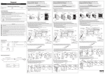
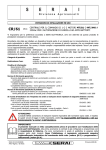
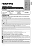
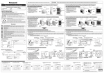
How to Install Base Pan Heater to Bi-bloc Unit (WH-UD03* and WH-UD05* Models) F615546 Before installing the Base Pan Heater, steps below need to be carried out to remove the exterior chassis. Base Pan Heater Installation Manual WARNING Be sure to switch off all power supply (i.e. indoor power supply, heater power supply, Tank Unit power supply) before performing the steps below to avoid electrical shock, etc. Required tools for Installation Works 1 Phillips screw driver 2 Glove 3 Cutter 4 Plier 5 Multimeter Step 1: Remove the Outdoor Unit Exterior Chassis 1. Locate and remove 5 mounting screws on the cabinet top plate, then pull to remove the plate. (refer Figure 1a) 2. Locate and remove 6 mounting screws on the cabinet front plate, then pull to remove the plate. (refer Figure 1b) SAFETY PRECAUTIONS Figure 1a Read the following “SAFETY PRECAUTIONS” carefully before installation. Electrical work must be installed by a licensed electrician. The caution items stated here must be followed because these important contents are related to safety. The meaning of each indication used is as below. Incorrect installation due to ignoring of the instruction will cause harm or damage, and the seriousness is classified by the following indications. WARNING This indication shows the possibility of causing death or serious injury. CAUTION This indication shows the possibility of causing injury or damage to properties only. Figure 1b Cabinet Front Plate Screws Cabinet Top Plate The items to be followed are classified by the symbols: Symbol with white background denotes item that is PROHIBITED from doing. Screws Symbol with dark background denotes item that must be carried out. Step 2: Installation Work: Guide Base Pan Heater (heating cable side) Carry out test run to confirm that no abnormality occurs after the installation. Then, explain to user the operation, care and maintenance as stated in instructions. Please remind the customer to keep the operating instructions for future reference. WARNING 1) Be sure to disconnect all power supply before install and connect the Base Pan Heater. Otherwise, it will cause electrical shock. 2) Engage authorized dealer or specialist for installation. If installation done by the user is defective, it will cause electrical shock or fire. 3) Install the Base Pan Heater strictly according to this installation instruction to prevent electrical shock or fire. 1. Check and identify the Base Pan Heater’s heating cable side. (refer Base Pan Heater Specification) 2. Locate the Black Marking of the Base Pan Heater and from this point, fix it on the base pan using band 2 as shown in Figure 2a. 3. Install the remaining Base Pan Heater (which include partial cold cable side) according to the routing guide as shown in Figure 2a. 4. Ensure each Base Pan Heater fixing point on the base pan use the correct band 2 and band 3 respectively. 5. During Base Pan Heater installation, ensure the entire fixed heating cable side has a contact with the base pan surface. 6. Do not remove the outdoor unit propeller fan and other parts or components during installation of the Base Pan Heater. Guide the Base Pan Heater 1 at both side of the band 2 Figure 2a Fan Motor Bracket Band 3 x 4 Condenser End Splice 4) Use only the attached accessory parts for installation to prevent electrical shock or fire. 5) For electrical work, follow the local wiring standard, regulation and this installation instruction. Otherwise, it will cause the electrical shock or fire. 6) The Base Pan Heater must be routed and installed properly to prevent the damage of outdoor unit or electrical shock or fire. 1 7) Do not modify the length of the Base Pan Heater lead wires. Otherwise, it will cause abnormal operations, fire or electrical shocks. Base Pan 8) Wear protective glove and use proper tools for installation work to prevent injury from metal parts or sharp edges. 9) Do not touch the heating cable side when the Base Pan Heater is activated. Otherwise, it will cause injury due to high temperature of the heating cable side surface. Band 2 x 6 Black Marking Step 3: Installation Work: Guide Base Pan Heater (cold cable side) 1. Locate the adjustable cable tie as shown in Figure 3a. 2. Untie the adjustable cable tie with the following 2 steps:1 Pull Attached Accessory No. Accessory Part 2 Push Qty. No. Accessory Part Base Pan Heater Qty. Band 1 1 3 4 3. Tie the Base Pan Heater’s cold cable side with the adjustable cable tie. (refer Figure 3a) 4. Ensure the cold cable side is not dangling after tying with the adjustable cable tie. Otherwise, it will be cut by the propeller fan blade. 5. Insert the cold cable side through the bushing on the sound proof board. 6. Detach the compressor sound proof material Velcro fastener to guide through the cold cable side. Then, strap back the Velcro. (refer Figure 3b) 7. Guide the cold cable side upward and through the inner side of the compressor discharge tube. 8. Connect the Base Pan Heater to the provided BLUE connector of outdoor unit PCB. Band Guide through the inner side of the compressor discharge tube Sound Proof Board 2 Guide the Base Pan Heater 1 through the bushing on the sound proof board. 6 Compressor Sound Proof Material Provided Connector (Blue Colour) Tie the Base Pan Heater 1 cold cable side with the adjustable cable tie on the sound proof board. Base Pan Heater Specification Velcro Fastener Base Pan Heater 1 Figure 3b Figure 3a Heating Cable Side Cold Cable Side Cable length: 1400 mm Cable length: 1050 mm Step 4: Switch on the Base Pan Heater Control in Indoor Unit 1. Remove the exterior chassis of indoor unit to access the PCB. 2. On top right of the PCB, search for DIP switch SW2. (refer Figure 4a and Figure 4b) 3. Set the DIP switch SW2 no. 3 from OFF to ON to activate the Base Pan Heater function. (refer Figure 4c) Inkjet marking: CSC2E 1.4m/70W/230V - CE SW2 C66 Connector SW2 1 J165 ON 1 J185 NO ON CN-TH1 Figure 4b Before After Figure 4c 31 2 1 6 CN-TH2 Indoor Unit’s PCB Figure 4a NO ON ) C1 CN-CPU J183 20mm 3 J182 Minimum bending radius J166 159 158 157 TH4 (RED) 60 70W ±10% J184 C3 IP 67 Power 1 Protection class SW2 OFF 1 (YLW) 4 CN-TH5 NO J188 R OFF 1 2 3 4 OFF 1 2 3 4 Black Marking CSC2E 1.4m/70W/230V~ - DO NOT CUT THE CABLE -A341091 - CE -Batch n˚ 1 2 3 4 End Splice ENGLISH F615546 1 13 PRINTED IN MALAYSIA