Transcript
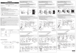
Be sure to switch off all power supply (i.e. indoor power supply, heater power supply, Tank Unit power supply) before performing the steps below to avoid electrical shocks, etc. WARNING Before installing the Base Pan Heater, steps below need to be carried out to remove the exterior chassis. F616192 Base Pan Heater Installation Manual Step 1: Removal of the Outdoor Unit Cabinet Plate Required tools for Installation Works 1 Philips screw driver 2 Glove 3 Cutter 4 Plier 1. Locate and remove 9 mounting screws on the cabinet top plate then remove the plate. Refer to Figure 1a. 2. Locate and remove the screws on the bottom of cabinet front plate then slide down and pull to remove the plate. Refer to Figure 1b. 3. Locate and remove 8 screws on the cabinet front plate then unhook it and pull to remove the plate. Refer to Figure 1c. 5 Multimeter SAFETY PRECAUTIONS Read the following “SAFETY PRECAUTIONS” carefully before installation. Electrical work must be installed by a licensed electrician. The caution items stated here must be followed because these important contents are related to safety. The meaning of each indication used is as below. Incorrect installation due to ignoring of the instruction will cause harm or damage, and the seriousness is classified by the following indications. WARNING This indication shows the possibility of causing death or serious injury. CAUTION This indication shows the possibility of causing injury or damage to properties only. Figure 1a Cabinet Top Plate Step 1: Removal of the Outdoor Unit Cabinet Plate Figure 1c Figure 1b Hook Cabinet Front Plate Mounting Screws Mounting Screws Mounting Screws Mounting Screws 1. Locate and remove 9 mounting screws on the cabinet top plate then remove the plate. Refer to Figure 1a. 2. Locate and remove the screws on the bottom of cabinet front plate then slide down and pull to remove the plate. Refer to Figure 1b. 3. Locate and remove 5 screws on the cabinet front plate then unhook it and pull to remove the plate. Refer to Figure 1c. Figure 1a Figure 1b Figure 1c Left Cabinet Front Plate Cabinet Top Plate Hook Mounting screws Cabinet Front Plate Hook Mounting screws Mounting Screws Step 1: Removal of the Cabinet Plate Symbol with white background denotes item that is PROHIBITED from doing. Symbol with dark background denotes item that must be carried out. Carry out test run to confirm that no abnormality occurs after the installation. Then, explain to user the operation, care and maintenance as stated in instructions. Please remind the customer to keep the operating instructions for future reference. WARNING 1) Be sure to disconnect all power supply before install and connect the Base Pan Heater. Otherwise, it will cause the electrical shock. 2) Engage authorized dealer or specialist for installation. If installation done is defective, it will cause electrical shock or fire. 1. Locate and remove the 5 mounting screws, slide down the cabinet and pull toward front to remove the right Cabinet Front Plate. Refer Figure 1a. 2. Locate and remove the 11 mounting screws, Lift up the Cabinet Top Plate to remove it from fixing. Refer Figure 1b. 3. Locate and remove the 5 mounting screws, slide downward and pull toward front to remove the middle Cabinet Front Plate. Refer Figure 1c. 4. Locate and remove 8 screws on the left Cabinet Front Plate then unhook it and pull to remove the plate. Refer to Figure 1d. Figure 1a Figure 1b How to Install Base Pan Heater to Mono bloc Unit (Single Fan WH-M* Models) Mounting screws Step 1: Removal of the Cabinet Plate Figure 1c Figure 1d Hook Cabinet Top Plate Mounting screws Middle Cabinet Front Plate Mounting screws Mounting screws Mounting screws Mounting screws Figure 1a 1. Locate and remove the 5 mounting screws, slide down the cabinet and pull toward front to remove the right Cabinet Front Plate. Refer Figure 1a. 2. Locate and remove the 11 mounting screws, Lift up the Cabinet Top Plate to remove it from fixing. Refer Figure 1b. 3. Locate and remove the 4 mounting screws, slide downward and pull toward front to remove the middle Cabinet Front Plate. Refer Figure 1c. 4. Locate and remove 5 screws on the left Cabinet Front Plate then unhook it and pull to remove the plate. Refer to Figure 1d. Left Cabinet Front Plate Right Cabinet Front Plate Mounting screws Mounting Screws How to Install Base Pan Heater to Mono bloc Unit (Double Fan WH-M* Models) The items to be followed are classified by the symbols: How to Install Base Pan Heater to Bi-bloc Unit (Single Fan WH-U* Models) How to Install Base Pan Heater to Bi-bloc Unit (Double Fan WH-U* Models) Mounting screws Figure 1b Figure 1c Mounting screws Cabinet Top Plate Mounting screws Right Cabinet Front Plate Figure 1d Left Cabinet Front Plate Middle Cabinet Front Plate Hook Mounting screws Hook Mounting screws Mounting screws 3) Install according to this installation instructions strictly. If installation done is defective, it will cause electrical shock or fire. 4) Use the attached accessories parts and specified parts for installation. Otherwise, it will cause fire or electrical shock. Step 2: Installation Work: Guide Base Pan Heater (for heating cable side) Step 2: Installation Work: Guide Base Pan Heater (for heating cable side) 5) For electrical work, follow the local national wiring standard, regulation and this installation instruction. Otherwise, it will cause the electrical shock or fire. 6) Heater routing must be properly arrange so that the set can be fixed properly. Or else it will damage by the propeller fan etc. that may damage the set. 7) Do not modify the length of the Base Pan Heater lead wires. Otherwise, it will cause abnormal operations, fire or electrical shocks. 8) Use glove and proper tools when doing installation job to prevent cutting by metal part or any sharp edges part. 1. Identify the heating cable side from end splice to the black marking. (refer to the base pan heater specification) 2. Begin guiding the heating cable from end splice. Fix the heating cable with 1st, 2nd, 3rd, 4th and 5th band 2 (refer to Figure 2a). 3. Use cable tie 3 to tie the heater with the bottom tube of condenser (refer Figure 2b) and fix the heater with 6th, 7th and 8th band. Make sure the heater is as near as possible to the condenser side. 4. Continue guide the heater follow the routing, insert the heater below the condenser where possible and make sure the heater is between the condenser and water discharge hole. 5. When the heater reaches the end, turn back to the opposite direction toward the fan motor bracket and tie the cable with the cable tie 3 provided after the black marking on the cable. Refer Figure 2c. * Note: - All heating cable should touch to the base pan. - It is not encourage to remove the Propeller Fan during installation of the base pan heater. 1. Identify the heating cable side from end splice to the black marking. (refer to the base pan heater specification) 2. Begin guiding the heating cable from end splice. Fix the heating cable with 1st, 2nd, 3rd, 4th and 5th band 2 (refer to Figure 2a). 3. Use cable tie 3 to tie the heater with the bottom tube of condenser (refer Figure 2b) and fix the heater with 6th, 7th and 8th band. Make sure the heater is as near as possible to the condenser side. 4. Continue guide the heater follow the routing, insert the heater below the condenser where possible and make sure the heater is between the condenser and water discharge hole. 5. When the heater reaches the end, turn back to the opposite direction toward the fan motor bracket and tie the cable with the cable tie 3 provided after the black marking on the cable. Refer Figure 2c. * Note: - All heating cable should touch to the base pan. - It is not encourage to remove the Propeller Fan during installation of the base pan heater. Figure 2 Figure 2 9) Do not touch to the heating cable when the Base Pan Heater is on. It will cause injured due to high temperature at heating cable’s surface. Fan Motor Bracket Guide through the band hole near to the Condenser Base Pan Heater 1 must pass by these holes 1 Fan Motor Bracket Base Pan Heater 1 must pass by these holes Fan Motor Bracket Guide through the band hole near to the Condenser Turn at this point Attached Accessory Condenser Qty. No. Accessory Part Base Pan Heater 2 Qty. 1 1 1 Cable Tie 1 3 Insert to this 2-diameter 5mm holes 2 Band Insert to this 2-diameter 5mm holes 3 2b 3 How to fixed Base Pan Heater 1 with band 2 Black marking 2a End splice Start guide from here Total 8 position 2 2x8 1 Make sure this black marking is before the cable tie and touch to base pan CSC2E 1.7m/85W/230V~ - DO NOT CUT THE CABLE -A341075 - CE -Batch n˚ Protection class IP 67 Power 85W ±10% Minimum bending radius 20mm Make sure this black marking is before the cable tie and touch to base pan Refrigerant Piping Outdoor PCB (refrigerant system) 2 Push 2. Tie the cold cable at these 2 position with the existing cable (refer Figure 3a). Make sure no dangling cables after tying the cables. Any dangling cable will cause fan’s blade to cut the cable. 3. Guide the cold cable through the second band on the control board. 4. Guide the cold cable through the twisted band. (Refer to Figure 3b) 5. On the Outdoor PCB (refrigerant system), locate CN-HT2 (BLACK). Unplug the dummy connector, then replace with base pan heater cable’s connector. Refer to Figure 3c, 3d and 3e. 3c Please tie up the 3b base pan heater Please tie up the with these 3 base pan heater 3a adjustable band with these 2 Fan Motor Sound Proof adjustable band Bracket Board Remove this dummy connector 3d Figure 3 3e Plug in the base pan heater cable’s connector Outdoor PCB (refrigerant Outdoor PCB (refrigerant system) system) Condenser CN-HT2 (BLACK) Connector Insert through this hole 2. Tie the cold cable at these 3 position with the existing cable (refer Figure 3a). Make sure no dangling cables after tying the cables. Any dangling cable will cause fan’s blade to cut the cable. 3. Insert the cold cable through a hole on the sound proof board. (Follow fan motor’s cable routing) 4. Upon insertion, tie the cable to the another 2 adjustable cable ties. Refer to Figure 3b. 5. On the Outdoor PCB (refrigerant system), locate CN-HT2 (BLACK). Unplug the dummy connector, then replace with base pan heater cable’s connector. Refer to Figure 3c, 3d and 3e. 2c Base pan Pass by this hole Outdoor PCB (refrigerant system) 1 Pull Outdoor PCB (refrigerant system) CN-HT2 (BLACK) Black Marking 1 Step 3: Installation Work: Guide Base Pan Heater (cold cable side) Figure 3 2 Push End Splice Black marking 2x8 End splice Start guide from here 1. Locate the 2 adjustable cable tie (refer to Figure 3a). Untie them by follow the step below: 1 Pull Inkjet marking: CSC2E 1.7m/85W/230V - CE 2b Total 8 position Step 3: Installation Work: Guide Base Pan Heater (cold cable side) Cold cable length: 1600 mm 3 2a 1. Locate the 3 adjustable cable tie (refer to Figure 3a). Untie them by follow the step below: Base Pan Heater Specification 3 How to fixed Base Pan Heater 1 with band 2 2c Base pan Pass by this hole 8 Heating cable length: 1700 mm Fan Motor Bracket Condenser 2 No. Accessory Part 1 Turn at this point 3c 3a Please tie up the base pan heater with these 2 adjustable band Remove this dummy connector Please guide the 3b Please tie up cold cable cold cable through with this adjustable band the second band 3d Plug in the base pan heater cable’s connector 3e Step 4: Activate the Base Pan Heater Control using control panel/remote controller 1. Press and Hold the SET and CHECK buttons together for 5 secs. TIMER OUTDOOR 3. Press the or button to scroll until the next screen appear. 2. The screen will show as below. TIMER ACTUAL OUTDOOR TIMER ACTUAL OPERATION OUTDOOR OPERATION WATER OUTLET OPERATION WATER OUTLET OFF/ON OFF/ON TIMER SETTING SET MODE STATUS CHECK TIMER SETTING SET OPERATION WATER SELECT QUIET HEATER SEARCH CANCEL HOLIDAY ERROR RESET SERVICE CLOCK CLOCK FORCE STATUS CHECK TIMER SETTING SET SELECT OFF/ON MODE QUIET TIMER OPERATION OPERATION WATER OUTLET OFF/ON TIMER SETTING SET MODE STATUS CHECK TIMER SETTING SET SELECT OFF/ON MODE QUIET OUTDOOR ACTUAL WATER OFF/ON SETTING STATUS OPERATION WATER OFF/ON TIMER SETTING SET SELECT OFF/ON MODE QUIET OFF/ON SETTING STATUS OPERATION WATER OUTLET OFF/ON TIMER SETTING SET MODE STATUS CHECK TIMER SETTING SET SELECT OFF/ON MODE 7. Press the or button to scroll to the next item. 8. Press the SELECT button to change setting. 9. Press the or button to scroll to choose ' ' or ' '. TIMER FORCE SELECT QUIET HEATER SEARCH CANCEL HOLIDAY ERROR RESET SERVICE CLOCK FORCE CANCEL HOLIDAY OFF/ON CLOCK FORCE SELECT QUIET HEATER SEARCH CANCEL HOLIDAY ERROR RESET SERVICE OUTDOOR ACTUAL SETTING STATUS QUIET OPERATION OFF/ON OFF/ON MODE 6. Press the SET button to confirm setting. ACTUAL WATER OFF/ON SETTING STATUS 5. Press the or button to select '. either ' ' or ' 4. Press the SELECT button to change setting. Data Range ' '/' ' 10. Press SET button to confirm the setting. 11. Press CANCEL button to exit system setting. TIMER SETTING SET OFF/ON CLOCK FORCE MODE SELECT QUIET CANCEL HOLIDAY WATER OUTLET OFF/ON CLOCK FORCE CANCEL HOLIDAY CLOCK FORCE CANCEL HOLIDAY OFF/ON CLOCK FORCE SELECT QUIET HEATER SEARCH CANCEL HOLIDAY ERROR RESET SERVICE CLOCK FORCE CANCEL HOLIDAY Note: Type ' ': AUTO Mode (Heater will only operate during Deice period) (Factory default setting) Type ' ': ON Mode (Heater will always operate when outdoor Temp 5°C) ENGLISH F616192 1 13 PRINTED IN MALAYSIA