1
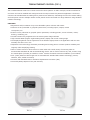
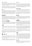
Tesira®
TEC-1s & TEC-1i
Operation/Installation
Manual
October 2012
Biamp Systems, 9300 SW Gemini Drive, Beaverton, Oregon 97008 U.S.A.
(503) 641-7287
www.biamp.com
TABLE OF CONTENTS
TESIRA ETHERNET CONTROL (TEC-1) FEATURES. . . . . . . . . . . . . . . . . . . . . . . . . . 3
FRONT PANEL. . . . . . . . . . . . . . . . . . . . . . . . . . . . . . . . . . . . . . . . . . . . . . . . . . . . . . . 4
Setup and Use. . . . . . . . . . . . . . . . . . . . . . . . . . . . . . . . . . . . . . . . . . . . . . . . . . . . 4
Display. . . . . . . . . . . . . . . . . . . . . . . . . . . . . . . . . . . . . . . . . . . . . . . . . . . . . . . . . . 4
Capacitive-touch Scroll Wheel. . . . . . . . . . . . . . . . . . . . . . . . . . . . . . . . . . . . . . . . 4
BACK PANEL . . . . . . . . . . . . . . . . . . . . . . . . . . . . . . . . . . . . . . . . . . . . . . . . . . . . . . . 5
Connectors. . . . . . . . . . . . . . . . . . . . . . . . . . . . . . . . . . . . . . . . . . . . . . . . . . . . . . . 5
SET UP . . . . . . . . . . . . . . . . . . . . . . . . . . . . . . . . . . . . . . . . . . . . . . . . . . . . . . . . . . . 6-9
Device Setup Mode . . . . . . . .
Edit Device ID . . . . . . . . . . . .
Edit Network Configuration. .
Edit Unlock Code . . . . . . . . . .
Edit Display Brightness . . . .
Edit Timeouts . . . . . . . . . . . .
View Device Information. . . .
Reset to Factory Defaults . . .
Exit . . . . . . . . . . . . . . . . . . . .
.
.
.
.
.
.
.
.
.
.
.
.
.
.
.
.
.
.
.
.
.
.
.
.
.
.
.
.
.
.
.
.
.
.
.
.
.
.
.
.
.
.
.
.
.
.
.
.
.
.
.
.
.
.
.
.
.
.
.
.
.
.
.
.
.
.
.
.
.
.
.
.
.
.
.
.
.
.
.
.
.
.
.
.
.
.
.
.
.
.
.
.
.
.
.
.
.
.
.
.
.
.
.
.
.
.
.
.
.
.
.
.
.
.
.
.
.
.
.
.
.
.
.
.
.
.
.
.
.
.
.
.
.
.
.
.
.
.
.
.
.
.
.
.
.
.
.
.
.
.
.
.
.
.
.
.
.
.
.
.
.
.
.
.
.
.
.
.
.
.
.
.
.
.
.
.
.
.
.
.
.
.
.
.
.
.
.
.
.
.
.
.
.
.
.
.
.
.
.
.
.
.
.
.
.
.
.
.
.
.
.
.
.
.
.
.
.
.
.
.
.
.
.
.
.
.
.
.
.
.
.
.
.
.
.
.
.
.
.
.
.
.
.
.
.
.
.
.
.
.
.
.
.
.
.
.
.
.
.
.
.
.
.
.
.
.
.
.
.
.
.
.
.
.
.
.
.
.
.
.
.
.
.
.
.
.
.
.
.
.
.
.
.
.
.
.
.
.
.
.
.
.
.
.
.
.
.
.
.
.
.
.
.
.
.
.
.
.
.
.
.
.
.
.
.
.
.
.
.
.
.
.
.
.
.
.
.
.
.
.
.
.
.
.
.
.
.
.
.
.
.
.
.
.
.
.
.
.
.
.
6
7
7
8
8
8
9
9
9
INSTALLATION . . . . . . . . . . . . . . . . . . . . . . . . . . . . . . . . . . . . . . . . . . . . . . . . . . . 10-13
TEC-1s Surface Mount Installation . . . . . . . . . . . . . . . . . . . . . . . . . . . . . . . . . . . 10
TEC-1i Flush Mount Installation . . . . . . . . . . . . . . . . . . . . . . . . . . . . . . . . . . . . . 11
Wiring . . . . . . . . . . . . . . . . . . . . . . . . . . . . . . . . . . . . . . . . . . . . . . . . . . . . . . . . . 13
SPECIFICATIONS . . . . . . . . . . . . . . . . . . . . . . . . . . . . . . . . . . . . . . . . . . . . . . . . . . . 14
WARRANTY. . . . . . . . . . . . . . . . . . . . . . . . . . . . . . . . . . . . . . . . . . . . . . . . . . . . . . . . 15
FCC COMPLIANCE . . . . . . . . . . . . . . . . . . . . . . . . . . . . . . . . . . . . . . . . . . . . . . . . . . 16
EC DECLARATION . . . . . . . . . . . . . . . . . . . . . . . . . . . . . . . . . . . . . . . . . . . . . . . . . . 17
EU RoHS COMPLIANCE . . . . . . . . . . . . . . . . . . . . . . . . . . . . . . . . . . . . . . . . . . . . . . 18
2
TESIRA ETHERNET CONTROL (TEC-1)
TEC-1 Tesira Ethernet Control is a remote control for Tesira systems. It offers a simple, intuitive interface for
end users and can be installed and configured to fit the unique needs of a particular application. The device
connects via standard Ethernet cabling and is powered over Ethernet, eliminating the need for custom cabling
and local power sources. Multiple remote control panels can be connected over large distances using standard
network technology.
FEATURES
• Adjustment and/or initiation of up to 32 selectable system volumes and actions
• Volumes are any individual or grouped system levels, including inputs, outputs, matrix
cross-points, etc.
• Actions are any individual or grouped system operations, including presets, source selection, mutes,
ducking, combining, etc.
• Control functions are programmed in the Tesira system design software
• High contrast OLED (Organic Light-Emitting Diode) display with a wide viewing angle
• The display brightness can be adjusted to fit the ambient light present in the application and can automatically dim when not in use
• Capacitive touch technology eliminates protruding and moving parts to increase product reliability and
longevity while simplifying cleaning
• TEC-1s surface mounts or flush mounts to most walls with a wide variety of mounting holes to
accommodate standard US and international back boxes. TEC-1i flush mounts to any wall; mounts using
the retrofit plate (included) or installs in a Raco® 254 box for North American installation (not included)
• 330' (100m) Ethernet cable length can be extended with standard PoE network technology (routers,
switches, hubs, media converters)
• Connects with standard RJ45 or insulation displacement connector (IDC)
• Covered by Biamp Systems’ five-year warranty
TEC-1i
TEC-1s
3
TEC-1 FRONT PANEL
Select
Scroll
Latch
Setup and Use
The Tesira software provides an intuitive interface for setup and programming of the TEC-1. The information
supplied by this manual relates to physical connections and device setup. For more details on software setup,
please consult the Tesira Help File.
Display
A graphic OLED (Organic Light-Emitting Diode) display with white characters on a black background shows a
list of all control items available from that panel, as well as the last selected item. If a control item includes
a volume control assignment, the bottom of the display will show a graphical representation of a volume bar
with the current level indicated to the right (percentage of maximum level).
Capacitive-touch Scroll Wheel
The capacitive-touch sensor provides a sleek interface for menu navigation and selection. The glossy-finish finger
groove allows for scrolling through and selecting available control items, as well as adjusting volume.
4
TEC-1 BACK PANEL
Connectors
Two Ethernet connectors—one rear-facing RJ45 and one top-facing insulation displacement connector
(IDC)—are provided for connecting to the network. Only one connector may be used. The RJ45 and IDC
utilize unshielded twisted pair (UTP) wiring to connect to a Tesira system. This connection is made to the
Ethernet port of a Tesira unit, either directly (single station) or via a network switch, and carries control
data over Ethernet.
The TEC-1 is powered using IEEE 802.3-2008 Power over Ethernet protocol as Class 1 devices. Either a PoEcapable network switch or a PoE injector is required to power the device; there are no other provisions for
power inlet.
TEC-1
Ethernet switch
with PoE
TEC-1
Ethernet switch
without PoE
PoE
injector
5
AC Power
TEC-1 SET UP
Device Setup Mode
The TEC-1 can be configured without connecting to a functional Tesira network. To enter setup mode,
connect the TEC-1 to a PoE source and place the jumper or any metal object across the locksmith pins.
When configuration is complete, remove the jumper and attach it to only one pin to resume normal
operation. Please note: many of the configuration settings can be accessed via the Tesira software.
Locksmith: Bridge
jumper pins to enter
setup mode
The cursor has two modes: select and modify. In select mode, the cursor appears as a gray box. When
scrolling through the available items in the list, the gray box will highlight the current selection.
“Select” mode in
device setup menu
On fields that can be modified, use the Select button to transition to and from modify mode. In modify mode,
the cursor appears as an outline box. Use the scroll wheel to adjust the setting up or down.
“Modify” mode in
device setup menu
Some screens have additional buttons that are used to accept (OK), reset, or cancel changed settings. Use the
scroll wheel to navigate the cursor to these buttons and press the Select button. The OK button saves the setting and exits the screen. The Reset button clears the setting and does not save it. The Cancel button exits the
screen without saving the setting.
6
TEC-1 SET UP
Edit Device ID
To name the unit, scroll to the ID Tag icon and press the Select button. Use the scroll wheel and Select button
to select the desired characters. Scroll to the
icon and select it to delete the previous character. The default
Device ID is “TEC-1ID 01”. The Device ID must match that of a corresponding block in the Tesira design. More
than one unit may be identified with the same design block (same ID). Device IDs may also be assigned via
Device Maintenance in the Tesira software.
Edit Network Configuration
To edit the network configuration, scroll to the Network icon and press the Select button. The default setting
(Auto) allows the device to receive its network configuration from a DHCP server. This allows TEC-1 to be
discovered by a Tesira device that also has default settings. The default hostname is “TEC-1-” followed by its
serial number. Select the hostname to edit it in a similar way of editing the device ID. The network settings
may instead be assigned via Device Maintenance in the Tesira software.
To specify a static IP address, change the “Auto IP?” to Static and select the IP address. TEC-1 will display the
Edit IP Address screen where the IP address, network mask, and gateway can be edited. Resetting the IP
address sets the IP address, network mask, and gateway back to 0.
7
TEC-1 SET UP
Edit Unlock Code
To set password protection, scroll to the Key icon and press the Select button. Use the scroll wheel and Select
button to choose the desired characters. During normal operation, holding down the Select button for five seconds will lock the unit, and the user will be prompted for the Lock Code before obtaining access. Lock Codes
may also be assigned via Device Maintenance in the Tesira software.
Edit Display Brightness
To change the brightness of the OLED panel, scroll to the Display Brightness icon and press the Select button.
Use the scroll wheel and Select button to make adjustments. The first setting represents the normal operational display brightness, and the second setting represents the dim display brightness. Display brightness
cannot be assigned via Device Maintenance in the Tesira software.
Edit Timeouts
To change the lock, dim, and sleep timeouts, scroll to the Timeout icon and press the Select button. Use the
scroll wheel and Select button to make a selection. The Timeout can range from 5 seconds to 30 minutes or
none for the lock and dim timeouts; the sleep timeout cannot be none. Timeouts may instead be assigned via
Device Maintenance in the Tesira software.
8
TEC-1 SET UP
View Device Information
To view information regarding the specific unit, scroll to the Information icon and press the Select button. The
Serial Number, MAC Address, Firmware Version, Hostname, IP Address, network mask, and gateway are displayed. This is non-editable information. The Serial Number is helpful in identifying physical units/locations
when naming them via Device Maintenance in the Tesira software. The IP address information is useful only
when TEC-1 receives an IP address automatically to indicate what IP address it received. Use the scroll wheel
to navigate through the list of information. Press the Select button to exit this screen.
Reset to Factory Defaults
To reset to factory defaults scroll to the reset icon with the exclamation point and press the Select button.
To confirm, scroll to the Yes button and press the Select button. Otherwise selecting No will return back to
the device setup screen. Resetting to factory defaults clears all device maintenance parameters and restores
them to their default values. When resetting to factory defaults the firmware version remains unchanged.
Exit
To exit the setup screen, scroll to the Exit Door icon and press the Select button.
9
TEC-1s INSTALLATION
Surface Mount Installation The TEC-1s surface mounts to most walls and has a wide variety of mounting holes that accommodate
standard US and international back boxes.
84mm
3.3"
USA, Japan, Australia
60mm
84mm
2.36"
3.3"
EUR
Italy
including Germany, Sweden,
UK, Netherlands
Use a screw driver or other suitable tool to engage the latch at the bottom of the TEC-1s to detach the back
enclosure. When installing the TEC-1s using the RJ45 connector, guide the Ethernet cable through the rear
opening before attaching the TEC-1s to the wall. Connect the RJ45 and snap the front enclosure into the retention holes. When installing the TEC-1s using the IDC, use a drill bit to create a hole in the top, side, or rear
of the back enclosure along the indentations. Remove the Ethernet cable jacket and shielding.
Indentations
Wire here for use with IDC
10
TEC-1i INSTALLATION
Flush Mount Installation
The TEC-1i may be flush mounted using the retrofit plate (provided with the product) or a Raco® 254 box
(purchased from an electrical distributor). To install the TEC-1i, a hole must be cut in the wall to accommodate
the Raco 254 box or to use the retrofit plate. See the figures below.
11.75cm
4 5/8″
4 3/4″
12.07cm
Wall cut out dimensions
Mounting using
a Raco
SECTION
A-A 254 box
Mounting using
theA-A
retrofit plate
SECTION
11
TEC-1i INSTALLATION
Retrofit Plate
Raco 254 box
Trim Ring
Front Plate
Exploded view showing pieces required for mounting to the retrofit plate
or the Raco 254 box
When installing the TEC-1i using the retrofit plate or the back-box, fasten the trim ring using the four screws
provided to either the retrofit plate or the back-box. Once the trim ring has been fastened to the retrofit plate
or the back-box, guide the TEC-1i front plate at an angle into the top of the trim ring to seat the tabs on the
top of the front plate. Once this has been done rotate the bottom of the front plate towards the bottom of the
trim ring until it is seated in the trim ring via the bottom clip.
If the front plate needs to be removed use a screw driver or other suitable tool to engage the latch at the
bottom of the TEC-1i to detach from the trim ring.
Refer to page 13 for instructions regarding the use of the insulation displacement connector.
12
TEC-1 INSTALLATION
Connect the wire according to the color code silkscreened as text next to the IDC or as shown on the label
on the back enclosure (see figure below). The color code uses the T568A standard for wiring. When using the
T568B wiring scheme, please note that the orange wire pair (OR and WH/OR) and green wire pair (GR and
WH/GR) need to be swapped. After inserting the wires, press the tabs until the insulation is punctured with an
audible click. No wire stripping is necessary.
Insulation Displacement Connector (IDC)
IDC wiring scheme
Note the appropriate bend radius requirements for category cables as shown in the figure below.
Software support in Tesira configuration software Version 1.1 or later provides user programming of all remote
functions, network setup, device naming, and device maintenance.
Visit www.biamp.com to obtain firmware and software updates related to this product. To speak with an
Applications Engineer, please call 1.503.641.7287 or email [email protected].
13
TEC-1 SPECIFICATIONS
TEC-1s SPECIFICATIONS
Dimensions:
5.1”H x 4.7”W x 1.25”D (130mm x 120mm x 32mm)
Weight:
0.5 lb (0.2kg)
Power consumption:
PoE Class 1 (3.2W @ full display utilization)
Material:
PVC/ABS
Control cable requirements:
Unshielded twisted pair (UTP) wiring, 100BaseT interface (CAT-5/6/7 Ethernet cable) using either RJ45 or
Insulation Displacement Connector (IDC)
Control cable length:
330’ (100m) Ethernet cable length can be extended with standard PoE network technology
Devices per system:
Remote Ethernet Devices
(including NPS-1) per system
128
Remote Ethernet Devices
per Tesira unit
24
Control wiring topology:
Standard Ethernet network wiring
Control programming:
Each control configured for specific operation by the system design software
Compliance:
EU Directive 2002/95/EC (RoHS Directive)
CE marked
FCC
TEC-1i SPECIFICATIONS
Dimensions:
6.22"H x 5.82"W x 0.5"D (158mm x 148mm x 12.7mm)
Power consumption:
PoE Class 1 (3.2W @ full display utilization)
Control cable requirements:
Unshielded twisted pair (UTP) wiring, 100BaseT interface (CAT-5/6/7 Ethernet cable) using either RJ45 or
Insulation Displacement Connector (IDC)
Control cable length:
330' (100m) Ethernet cable length can be extended with standard PoE network technology
Control wiring topology:
Standard Ethernet network wiring
Control programming:
Each control configured for specific operation by the system design software
Compliance:
EU Directive 2002/95/EC (RoHS Directive)
CE marked
FCC
14
WARRANTY
BIAMP SYSTEMS IS PLEASED TO EXTEND THE FOLLOWING 5-YEAR LIMITED WARRANTY TO THE ORIGINAL
PURCHASER OF THE PROFESSIONAL SOUND EQUIPMENT DESCRIBED IN THIS MANUAL
1. Biamp Systems warrants to the original purchaser of new products that the product will be free from
defects in material and workmanship for a period of 5 YEARS from the date of purchase from an
authorized Biamp Systems dealer, subject to the terms and conditions set forth below.
2 If you notify Biamp during the warranty period that a Biamp Systems product fails to comply with the
warranty, Biamp Systems will repair or replace, at Biamp Systems’ option, the nonconforming product. As a
condition to receiving the benefits of this warranty, you must provide Biamp Systems with documentation
that establishes that you were the original purchaser of the products. Such evidence may consist of your
sales receipt from an authorized Biamp Systems dealer. Transportation and insurance charges to and
from the Biamp Systems factory for warranty service shall be your responsibility.
3. T
his warranty will be VOID if the serial number has been removed or defaced; or if the product has
been altered, subjected to damage, abuse or rental usage, repaired by any person not authorized by
Biamp Systems to make repairs; or installed in any manner that does not comply with Biamp Systems’
recommendations.
4. Electro-mechanical fans, electrolytic capacitors, gooseneck microphones, cords connecting handheld
microphones, hard-drives, displays, and normal wear and tear of items such as paint, knobs, handles,
keypads and covers are not covered under this warranty. All server-based devices are warranted for 3
years only.
5. This warranty is in lieu of all other warranties, expressed or implied. Biamp Systems disclaims all other
warranties, expressed or implied, including, but not limited to, implied warranties of merchantability
and fitness for a particular purpose.
6. The remedies set forth herein shall be the purchaser’s sole and exclusive remedies with respect to any
defective product.
7. No agent, employee, distributor or dealer of Biamp Systems is authorized to modify this warranty or to
make additional warranties on behalf of Biamp Systems. Statements, representations or warranties
made by any dealer do not constitute warranties by Biamp Systems. Biamp Systems shall not be
responsible or liable for any statement, representation or warranty made by any dealer or other person.
8. No action for breach of this warranty may be commenced more than one year after the expiration of
this warranty.
9. B
iamp Systems shall not be liable for special, indirect, incidental, or consequential damages, including
lost profits or loss of use arising out of the purchase, sale, or use of the products, even if Biamp
Systems was advised of the possibility of such damages.
101612_585.0316.90B
15
FCC COMPLIANCE
FCC NOTICE - CLASS B DIGITAL DEVICE
This equipment has been tested and found to comply with the limits for a Class B digital device, pursuant to Part
15 of the FCC Rules. These limits are designed to provide reasonable protection against harmful interference
when the equipment is operated in either a residential or commercial installation. This equipment generates,
uses and can radiate radio frequency energy and, if not installed and used in accordance with the instructions,
may cause harmful interference to radio communications. However, there is no guarantee that interference will
not occur in a particular installation. If this equipment does cause harmful interference to radio or television
reception, which can be determined by turning the equipment off and on, the user is encouraged to try to correct the interference by one or more of the following measures: 1) Reorient or relocate the receiving antenna,
2) Increase the separation between the equipment and receiver, 3) Connect the equipment into an outlet on a
circuit different from that to which the receiver is connected or 4) Consult the dealer or an experienced radio/TV
technician for help.
16
EC DECLARATION OF CONFORMITY
DoC TEC-201205d
EC Declaration of Conformity
Biamp Systems Corporation, as manufacturer having sole responsibility, hereby declares
that our delivered version the following described product complies with the applicable
provisions of the DIRECTIVES below except as noted herein. Any alterations to the product
not agreed upon and directed by Biamp Systems Corporation will invalidate this declaration.
Brand Name:
Tesira®
Product Description:
Remote Audio Controls for Networked Audio DSP Platform.
Models:
TEC-1i, TEC-1s
Applicable EC Directives:
Applicable Harmonized Standards:
LVD Directive (2006/95/EC)
Safety
EN 60065:2002
IEC 60065:2001 + Amd 1:2005
EMC Directive (2004/108/EC)
Emissions
Immunity
EN 55103-1:1996, Environment E2
EN 55103-2:1996, Environment E2
RoHS Directive (2011/65/EU)
RoHS Recast
Special Considerations for Product Environment or Compliance:
•
Use only PoE Insertion Devices that are CE Marked, certified to local regulations, and
appropriately rated Type 1 PoE or Type 2 PoE Plus (IEEE 802.3at).
•
Shielded cabling must be used for system connections.
Technical Construction File, Location and Contact:
Biamp Systems Corporation
9300 S.W. Gemini Drive
Beaverton, OR USA 97008
phone:
fax:
e-mail:
(503) 641.7287
(503) 626.0281
[email protected]
Authorized Representative:
Larry Copley, Compliance Engineer
Authorized Signature:
Date and Place Issued:
May 2012, Beaverton, Oregon USA
17
COMPLIANCE
EU RoHS COMPLIANT
This Biamp product, including all attendant cables and accessories
supplied by Biamp, meets all requirements of EU Directives
2002/95/EC of January 27, 2003, and 2005/618/EC of August 18,
2005, the EU RoHS Directives. An EU RoHS Materials Content
Declaration document may be obtained at www.biamp.com
(This information is presented to comply with the requirements of Chinese law SJ/T11363-2006)
有害物质表 (Hazardous Substances Table)
Biamp Systems Corporation
远程控制设备 (Remote Control Device)
Tesira TEC-1i, TEC-1s
部件名称 (Part Name)
设备机箱 (Equipment Chassis) 手册和其他书面文档 (Manual and Paper Documents)
包装箱和所有包装材料 (Box and Packing Materials)
Pb
铅
X
O
O
有毒有害物质或元素 (Substances)
Hg
Cd
Cr+6
PBB PBDE
汞
镉
六价铬
O
X
O
O
O
O
O
O
O
O
O
O
O
O
O
0:表示该部件所有均质材料中的这种有毒有害物质低于 SJ/T11363-2006 的限制要求.
X:表示该部件中至少有一种均质材料所含的这种有毒有害物质高于 SJ/T11363-2006 的限制要求.
在电触头和(或)镀镉所含的均质材料中,镉及其化合物的含量可以超过 0.01%,但欧盟指令 91/338/EEC(根据欧盟指令
76/769/EEC)限制销售和使用某些危险物质和制剂部分中所禁止的用途除外
在以下一种或多种物质所含的均质材料中,铅及其化合物的含量可以超过 0.1%:
1) 电子元器件中玻璃内所含的铅
2) 铅在钢材中是作为一种合金元素,含量可达 0.35%
3) 铅在铝材中是作为一种合金元素,含量可达 0.4%
4) 铅在铜材中是作为一种合金元素,含量可达 4%
5) 高熔点类焊料中的铅(即铅料合金,铅含量超过 85%)
6) 电子陶瓷部件内的铅
7) 由两种以上元素组成的焊料中所含的铅,用于连接针脚和微处理器包装,其中
铅的含量超过 80% 但低于 85%
8) 顺应针连接系统内的铅
9) 倒装芯片封装中半导体芯片及载体之间形成可靠连接所用焊料中的
在正常使用情况下,中国环保使用期限为 10 年,条件是:
• 环境温度为 0-40C (32-104°F)
• 湿度为 0-95%,无凝结
• 海拔高度为 0-10,000 英尺
• 气流不受阻碍
• 没有水或其他液体进入任何部件
• 电源为 PoE, IEEE 802.3af, Class 1
• 部件没有损坏(损坏部件应立即修理)
• ��������用��的����所有��
18