1
CPA 130
Power Amplifier
Operation Manual
Biamp Systems | 9300 S.W. Gemini Drive | Beaverton, OR | 97008 | USA | +1.503.641.7287 | www.biamp.com
CPA130
TABLE OF CONTENTS
Safety Information
pgs. 2~5
Front Panel
pg. 6
Rear Panel
pg. 7
Precautions
pg. 8
Internal Modifications
pg. 9
Specifications
pg. 10
Block Diagram
pg. 11
Warranty
pg. 12
CPA130
INTRODUCTION
CPA130 dual channel power amplifiers are designed to supply reliable service in permanent installations. CPA130
amplifiers have complete short-circuit and thermal protection with automatic reset. Barrier strip input and 5-way binding post
output connectors provide trouble free, dependable connections. CPA130 amplifiers are passively cooled for quiet
operation, without fan noise or filter maintenance. CPA130 amplifiers carry a five-year warranty.
CPA130 features include:
♦ balanced inputs on barrier strip terminals
♦ 65 watts/channel @ 4 ohms (stereo)
♦ 40 watts/channel @ 8 ohms (stereo)
♦ 130 watts @ 8 ohms (mono bridge)
♦ peak indicators on each channel
♦ detented level controls (front or rear mounting)
♦ complete short-circuit and thermal protection
♦ turn-on muting to prevent "thumping"
♦ selectable stereo or mono bridge operation
♦ internal jumpers select HPF (18dB/octave @ 180Hz)
♦ passively cooled (no fan noise or maintenance)
♦ optional distribution autoformers (rear panel mounting)
♦ covered by Biamp Systems' five-year warranty
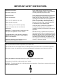
IMPORTANT SAFETY INSTRUCTIONS
Read these instructions.
Do not install near any heat sources such as
radiators, heat registers, stoves, or other apparatus
(including amplifiers) that produce heat.
Keep these instructions.
Heed all warnings.
Do not defeat the safety purpose of the polarized or
grounding-type plug. A polarized plug has two
blades with one wider than the other. A grounding
type plug has two blades and a third grounding
prong. The wide blade or the third prong are
provided for your safety. When the provided plug
does not fit into your outlet, consult an electrician
for replacement of the obsolete outlet.
Follow all instructions.
Do not use this apparatus near water.
Clean only with a dry cloth.
Do not block any of the ventilation openings.
Protect the power cord from being walked on or
pinched particularly at plugs, convenience
receptacles, and the point where they exit from the
apparatus.
Install in accordance with the manufacturers
instructions.
WARNING - To reduce the risk of electric shock, do
not expose this apparatus to rain or moisture.
Refer all servicing to qualified service personnel.
Servicing is required when the apparatus has been
damaged in any way, such as power-supply cord or
plug is damaged, liquid has been spilled or objects
have fallen into the apparatus, the apparatus has
been exposed to rain or moisture, does not operate
normally, or has been dropped.
The apparatus shall not be exposed to dripping or
splashing and no objects, such as vases, shall be
placed on the apparatus.
Unplug this apparatus during lightning storms or
when unused for long periods of time.
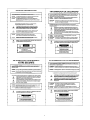
Use only attachments/accessories specified by the manufacturer.
Use only with the cart, stand, tripod, bracket, or table specified by the manufacturer or sold with the apparatus.
When a cart is used, use caution when moving the cart/apparatus combination to avoid injury from tip-over.
Unplug this apparatus during lightning storms or when unused for long periods of time.
The appliance inlet shall be readily operable once installed.
WARNING - Terminals marked with the following symbol are Hazardous. Connections to these teminals must be
made by qualified personnel.
2
3
4
5
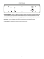
FRONT PANEL
Channel Peak Indicators: These red LED indicators will light when their respective channel amplifiers have reached maximum output.
To avoid clipping distortion, and to protect speakers from being damaged, reduce the input level until the Peak Indicator no longer lights.
Channel Level Control Mounting Holes: These holes are provided for optional front panel mounting of the channel level controls (see
Internal Modifications: Front Panel Level Controls on page 9). NOTE: Modifications must be performed by qualified service professionals.
Power Indicator: This green LED indicator will light when AC power is applied to the unit (see Precautions on page 8).
AC Power Switch: This switch applies AC power to the unit (see Precautions on page 8).
6
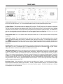
REAR PANEL
Autoformer Mounting Holes: These holes are for mounting of optional autoformers to the rear panel of the CPA130. Autoformers allow
the CPA130 to be used to drive 25V, 70V, or 100V distributed speaker systems (see 5-Way Speaker Binding Posts below).
AC Power Entrance: This receptacle accepts the detachable AC Power Cord. The AC Power Cord is for connection to three-prong
grounded AC outlets. CAUTION: Do not remove or defeat the ground prong on the AC Power Cord, as this constitutes a shock hazard.
The Fuse Clip may be removed by first detaching the AC Power Cord, then prying the Fuse Clip out from above, using a flat-blade
screwdriver in the notch provided. The Fuse Clip contains the standard fuse for the selected AC operational voltage. The standard fuse is
held in the clip, and becomes the actual AC fuse when the Fuse Clip is installed. Replace the standard fuse only with the same value and
type. For ~115 VAC operation, use a T 3A L 250V fuse. For ~230 VAC operation, use a T 1.6A L 250V fuse.
Voltage Selector Switch: For 115 VAC operation, slide to the left position toward 115V. For 230 VAC operation, slide to the right position
toward 230V.
Channel Level Controls: These controls adjust the input signal level for each channel. After setting appropriate levels at the signal
source, then adjust the Channel Level Controls for the desired output volume from the CPA130. In mono-bridge mode, Channel 1
becomes the active input and Channel 2 input is inactive. As an option, the Channel Level Controls may be mounted to the CPA130 front
panel (see Internal Modifications: Front Panel Level Controls on page 9). NOTE: Modifications must be performed by qualified service
professionals.
Input Barrier Strip: These barrier strip screw terminals are for connection of line-level input signals to the channels. For balanced inputs,
connect High to (+), Low to (-), and Ground to (gnd). For unbalanced inputs, connect High to (+) and Ground to both (-) & (gnd). In monobridge mode, Channel 1 becomes the active input and the Channel 2 input is inactive.
5-Way Speaker Binding Posts: These 5-way binding posts are for connection of speaker loads to the CPA130. In stereo mode, the red
(+) terminal of each channel is for connection to speaker positive, and the black (-) terminal for each channel is for connection to speaker
negative. The CPA130 will deliver up to 65 Watts per channel into 4 ohm minimum loads. In mono-bridge mode, the red (+) terminal of
Channel 1 is for connection to speaker positive, and the red (+) terminal of Channel 2 is for connection to speaker negative. The CPA130
will deliver up to 130 Watts mono-bridged into an 8 ohm minimum load. Autoformers are available from Biamp Systems, which allow the
CPA130 to be used to drive 25V, 70V, or 100V distributed speaker systems (see Internal Modifications: High-Pass Filter on page 5). When
using the CPA130 in stereo mode, the appropriate autoformer for each channel is a DT-2A. When using the CPA130 in mono-bridge
mode, the appropriate autoformer is a DT-3A.
Mono-Bridge Switch: When depressed, this switch selects the mono-bridge mode of operation. In mono-bridge mode, Channel 1
becomes the active input and the Channel 2 input is inactive. The red (+) speaker terminal of Channel 1 is for connection to speaker
positive, and the red (+) speaker terminal of Channel 2 is for connection to speaker negative. The CPA130 will deliver up to 130 Watts
mono-bridged into an 8 ohm minimum load.
7
PRECAUTIONS
Be sure that power to the CPA130 is turned off when making all connections. High voltages can be present at the speaker terminals, and
static pops or broken ground connections on cables can cause speaker damage.
Use speaker wire of sufficient gauge to prevent power loss and damping factor reduction. Larger size wire has a lower resistance and
permits longer cable runs. Use 16 or 18 gauge wire for cable runs up to 20 feet. For runs 20~80 feet, use 14 gauge wire. For runs longer
than 80 feet, use 10 or 12 gauge wire.
Check the AC voltage before connecting the AC cord. The voltage selector is indicated on the rear panel at the power cord receptacle.
The CPA130 is shipped from the factory set for 110VAC operation. If it is necessary to set the AC voltage selector for 240VAC operation,
be sure to replace the AC fuse with the appropriate value.
The High-Pass Filters must be enabled whenever using the CPA130 for driving distributed speaker systems (see Internal Modifications:
High-Pass Filter on page 5).
Never connect the red (+) speaker binding posts directly together. This can result in internal damage to the amplifier.
Before turning power on, set the CPA130 level controls to the fully counter-clockwise (off) position.
The CPA130 is designed to be installed in a standard 19" equipment rack. The amplifiers have cooling vents on both the top and bottom
panels. Do not block the cooling vents in any way. When mounting the CPA130 in a rack, leave at least one rack-space above and below
the amplifier to allow proper air flow. Do not use a CPA 130 in a closed rack. In situations with high ambient temperatures, particularly
where multiple amplifiers are mounted in the same rack, it may be necessary to use fans to cool the rack. Best results are attained if the
fans blow cool air in from the bottom of the rack, up through the amplifiers, expelling the heated air at the top.
If the green LED indicator next to the power switch does not light when the power switch is turned on, turn the power switch off and check
the AC power cord connections. If the power cord connections are complete, but the indicator still does not light, disconnect the CPA130
from AC power and check the AC fuse. If the fuse needs to be replaced, use the same value and type fuse only. If the AC fuse continues
to fail, the amplifier may require service.
Once power is turned on, slowly advance the level controls clockwise. If no sound is heard, turn the level controls back to their original
counter-clockwise position and check to confirm there is an input signal. Also check for proper wiring at all input and output connections,
and verify that the cables being used are undamaged and are in good condition.
If the CPA130 should require service, please contact Biamp Systems Customer Service at 1-800-826-1457 or (503) 641-7287.
8
INTERNAL MODIFICATIONS
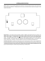
NOTE: Modifications must be performed by qualified service professionals. Disconnect the CPA130 from the AC outlet. Remove the top
panel to access internal modifications. The diagram below shows the printed circuit board (PCB) and components as they appear on each
amplifier channel module.
FILTER
IN
OUT
High-Pass Filter: This two-position jumper strap enables or disables a 18dB/octave 180Hz High-Pass Filter for that channel of the
amplifier. When the strap is in the "IN" (up) position, the High-Pass Filter is enabled. When the strap is in the "OUT" (down) position, the
High-Pass Filter is disabled. The High-Pass Filters must be enabled whenever the CPA130 is used for driving distributed speaker
systems. This eliminates excessive current at low frequencies due to speaker transformer inductance, which can cause distortion or
damage to the amplifier. If the CPA130 is used in mono-bridge mode to drive a distributed speaker system, it is only necessary for the
Channel 1 High-Pass Filter to be enabled. The CPA130 is shipped from the factory with the High-Pass Filters disabled ("OUT").
Front Panel Level Controls: The Channel Level Controls may be moved to the front panel of the CPA130. Remove the plugs from the
front panel mounting holes (save them for the rear panel mounting holes). Remove the knobs from the level controls. Remove the nuts
from the level controls using a 11mm (7/16") nut driver. Move the level controls to the front panel mounting holes (make sure that Channel
1 and Channel 2 level controls are in their proper locations). Re-install nuts and knobs (hold onto controls to avoid twisting wires). Install
plugs in rear panel mounting holes. Check wire routing to avoid pinching or over-heating of wires.
9
SPECIFICATIONS
Maximum Power Output (@ 2kHz):
both channels driven into 4 ohms
65 watts/channel
both channels driven into 8 ohms
40 watts/channel
mono bridge into 8 ohms
130 watts
Signal-to-Noise Ratio (20Hz~20kHz):
rated power into 4 ohms
> 96dB
Total Harmonic Distortion:
20Hz~20kHz @ rated power
< 0.2%
2kHz @ rated power (typical)
< 0.1%
Intermodulation Distortion (SMPTE):
< 0.35%
Frequency Response (20Hz~20kHz):
+0/-1dB
Input Impedance:
balanced
20k ohms
unbalanced
10k ohms
Input Sensitivity:
0.775 Vrms (0dBu)
Power Requirements:
120/240 VAC, 50/60Hz
Power Consumption:
300 watts max.
Dimensions:
height (2 rack-spaces)
3.5 inches (89mm)
width
19 inches (483mm)
depth
10 inches (254mm)
Weight:
22 lbs. (9.98kg)
10
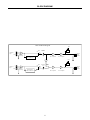
BLOCK DIAGRAM
CPA130 Block Diagram
Peak
HPF
+
Channnel 1
input
Signal
Detect
Channel 1
Level
Out
Gnd
Balanced
input Stage
Channel 1
Output
Common
In
High Pass Filter
180Hz, 18dB/octave
Driver Amplifier
Power Amplifier
Peak
HPF
+
Channnel 2
input
Gnd
Out
Balanced
input Stage
Signal
Detect
Mono
Bridge
Channel 2
Level
Channel 2
Output
Common
Stereo
High Pass Filter
180Hz, 18dB/octave
In
Driver Amplifier
11
Power Amplifier
WARRANTY
BIAMP SYSTEMS IS PLEASED TO EXTEND THE FOLLOWING 5-YEAR LIMITED WARRANTY TO THE
ORIGINAL PURCHASER OF THE PROFESSIONAL SOUND EQUIPMENT DESCRIBED IN THIS MANUAL
1. BIAMP Systems warrants to the original purchaser of new
products that the product will be free from defects in material
and workmanship for a period of 5 YEARS from the date of
purchase from an authorized BIAMP Systems dealer, subject to
the terms and conditions set forth below.
5.
THIS WARRANTY IS IN LIEU OF ALL OTHER
WARRANTIES, EXPRESS OR IMPLIED. BIAMP SYSTEMS
DISCLAIMS ALL OTHER WARRANTIES, EXPRESS OR
IMPLIED, INCLUDING, BUT NOT LIMITED TO, IMPLIED
WARRANTIES OF MERCHANTABILITY AND FITNESS FOR A
PARTICULAR PURPOSE.
2. If you notify BIAMP during the warranty period that a BIAMP
Systems product fails to comply with the warranty, BIAMP
Systems will repair or replace, at BIAMP Systems' option, the
nonconforming product. As a condition to receiving the benefits
of this warranty, you must provide BIAMP Systems with
documentation that establishes that you were the original
purchaser of the products. Such evidence may consist of your
sales receipt from an authorized BIAMP Systems dealer.
Transportation and insurance charges to and from the BIAMP
Systems factory for warranty service shall be your responsibility.
6. The remedies set forth herein shall be the purchaser's sole
and exclusive remedies with respect to any defective product.
7. No agent, employee, distributor or dealer of Biamp Systems
is authorized to modify this warranty or to make additional
warranties on behalf of Biamp Systems.
statements,
representations or warranties made by any dealer do not
constitute warranties by Biamp Systems. Biamp Systems shall
not be responsible or liable for any statement, representation or
warranty made by any dealer or other person.
3. This warranty will be VOID if the serial number has been
removed or defaced; or if the product has been altered,
subjected to damage, abuse or rental usage, repaired by any
person not authorized by BIAMP Systems to make repairs; or
installed in any manner that does not comply with BIAMP
Systems' recommendations.
8. No action for breach of this warranty may be commenced
more than one year after the expiration of this warranty.
9. BIAMP SYSTEMS SHALL NOT BE LIABLE FOR SPECIAL,
INDIRECT, INCIDENTAL, OR CONSEQUENTIAL DAMAGES,
INCLUDING LOST PROFITS OR LOSS OF USE ARISING
OUT OF THE PURCHASE, SALE, OR USE OF THE
PRODUCTS, EVEN IF BIAMP SYSTEMS WAS ADVISED OF
THE POSSIBILITY OF SUCH DAMAGES.
4. Electro-mechanical fans, electrolytic capacitors, and normal
wear and tear of items such as paint, knobs, handles, and
covers are not covered under this warranty.
Biamp Systems
9300 S.W. Gemini Drive
Beaverton, Oregon 97008
(503) 641-7287
585.0070.90B
12
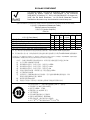
EU RoHS COMPLIANT
This Biamp product, including all attendant cables and accessories
supplied by Biamp, meets all requirements of EU Directives
2002/95/EC of January 27, 2003, and 2005/618/EC of August 18,
2005, the EU RoHS Directives. An EU RoHS Materials Content
Declaration document may be obtained at www.biamp.com
(This information is presented to comply with the requirements of Chinese law SJ/T11363-2006)
有害物质表 (Hazardous Substances Table)
Biamp Systems Corporation
音频放大器 (Audio Amplifier)
CPA130
部件名称 (Part Name)
设备机箱 (Equipment Chassis) 电源线 (Power Cord)
插拔式接线端子 (Plug-in Terminal Blocks)
手册和其他书面文档 (Manual and Paper Documents)
包装箱和所有包装材料 (Box and Packing Materials)
Pb
铅
X
O
O
O
O
有毒有害物质或元素 (Substances)
Hg
Cd
Cr+6
PBB PBDE
汞
镉
六价铬
O
X
O
O
O
O
O
O
O
O
O
O
O
O
O
O
O
O
O
O
O
O
O
O
O
0:表示该部件所有均质材料中的这种有毒有害物质低于 SJ/T11363-2006 的限制要求.
X:表示该部件中至少有一种均质材料所含的这种有毒有害物质高于 SJ/T11363-2006 的限制要求.
在电触头和(或)镀镉所含的均质材料中,镉及其化合物的含量可以超过 0.01%,但欧盟指令 91/338/EEC(根据欧盟指令
76/769/EEC)限制销售和使用某些危险物质和制剂部分中所禁止的用途除外
在以下一种或多种物质所含的均质材料中,铅及其化合物的含量可以超过 0.1%:
1) 电子元器件中玻璃内所含的铅
2) 铅在钢材中是作为一种合金元素,含量可达 0.35%
3) 铅在铝材中是作为一种合金元素,含量可达 0.4%
4) 铅在铜材中是作为一种合金元素,含量可达 4%
5) 高熔点类焊料中的铅(即铅料合金,铅含量超过 85%)
6) 电子陶瓷部件内的铅
7) 由两种以上元素组成的焊料中所含的铅,用于连接针脚和微处理器包装,其中
铅的含量超过 80% 但低于 85%
8) 顺应针连接系统内的铅
9) 倒装芯片封装中半导体芯片及载体之间形成可靠连接所用焊料中的
在正常使用情况下,中国环保使用期限为 10 年,条件是:
• 环境温度为 0-40C (32-104°F)
• 湿度为 0-95%,无凝结
• 海拔高度为 0-10,000 英尺
• 气流不受阻碍
• 没有水或其他液体进入任何部件
• 电源为 115/230V~, 50/60Hz
• 部件没有损坏(损坏部件应立即修理)
• 由工厂授权人员使用批准的材料进行所有维修
13